Keywords
|
| Array antenna, Mutual coupling, Space waves, EBG structures |
INTRODUCTION
|
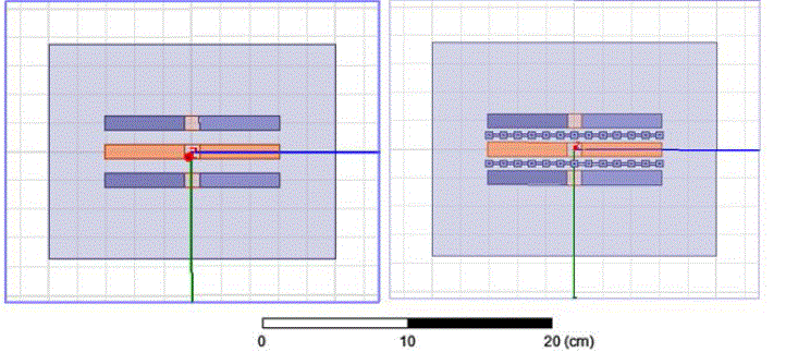
| In the open literature so many researches are done on the meta-materials also known as the artificial magnetic conductors. Originally these are implemented to suppress the surface wave’s propagation in the antennas [1]. But later these devices are utilized for several applications in wireless communications field to alter the antenna parameters without changing the antenna itself, by using these structures we can get the enhanced gain [2], bandwidth, and low return loss etc. And in the current paper the concept of surface wave suppression [8] is used for reducing the mutual coupling in the array antennas. Because these structures do not conduct AC current in the specified forbidden band. In the current paper the dipole antenna with 3 elements is taken with equal spacing and a line of EBG is place between them and the design is shown in the following figure [1]. |
EBG Structure Explanation
|
| The proposed mushroom-like EBG structure [3] consists of four parts: a ground plane, a dielectric substrate, metallic patches, and connecting vias. These structures have a distinct stop-band for surface-wave propagation. the operation of EBg cells can be explained by LC circuit here L is inductance due to the current flow in the via and C is capacitance due to fringing field in the gap between patches. |
| The L and C are determined by the following equations [4] |
| L=μoh (1) |
| C=Wεo(1+εr)cosh-1((2W+g)/g)/Π (2) |
| Where μo is the permeability of free space, εo is the permittivity of free space. W is patching width; g is gap between patches, h substrate thickness and εr is dielectric Constant. |
SIMULATION RESULTS
|
| A. Return loss curves |
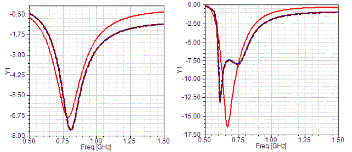
| The below figure [2] represents the return loss curves comparison for the designed antenna without and with EBG lines. |
| In the above figure it is clearly seen that with little BW reduction the return loss is reduced with the introduction of the EBG structure between the array elements the three curves represents the return loss for three port excitations for 3 array elements as S11, S22 and S33. |
| B. E,H-fields |
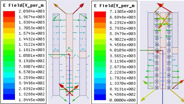
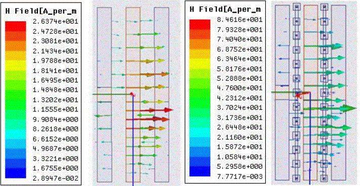
| The E,H- fields analysis explains how much the radiation energy is improved when the low mutual coupling is obtained by the EBG line, figures [3] & [4] shows the E,H field analysis comparison. Generally when the mutual coupling is high due to the insufficient spacing between the array elements to avoid this if we increase the spacing that may resulting large size of antenna to avoid this EBG cells are used to get low mutual coupling for array antennas. |
| In the above figure [3] for the designed antenna E-field have so many low quantities around 1 and few better values 9.1910, 7.8807, 6.5703, 5.2599 and 3.9496 but when the EBG is placed in the second part expect low quantities 1.7826 and 1.3370 remaining all are high values starting from 7.1305 to 2.2283. |
| C. Total Gain curves |
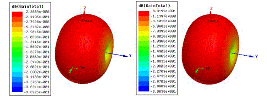
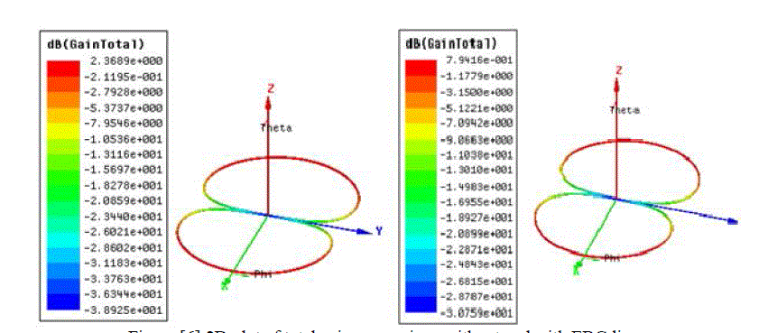
| The total gain curves in 3D plots and top view are represented in the following figures [5] and [6]. |
| In the above we figure [5] the analysed values can explains how much the radiation is improved when the low mutual coupling is obtained by using the EBG structure. In the first part of the figure the maximum gain is 2.3689dB here the curve represents the radiation in all directions and compared to this when EBG is placed the mutual coupling between the elements is reduced that in turn enhances the radiation into the surroundings and the maximum value is now 8.3199dB. |
| The above figure compares how much the enhancement is achieved in the phi=90degree region it is clear that it is improved from 2.3689 to 7.9416. That explains how much the gain is improved over the array antennas without changing the spacing between the elements. |
| In the above table the comparison will explains how much all parameters have been improvised with the EBG structure especially the main improvement is radiation efficiency when the mutual coupling is strong for the first case where the EBG is not present the efficiency is 80.16% but when the low mutual coupling is achieved due to the EBG presence between the array elements the efficiency is increased to 96.9354% |
CONCLUSION
|
| In the field of antennas several techniques have been implemented to achieve low mutual coupling for array antennas and each alter the specifications of antenna a little bit. Now the current research dealt with achieving the low mutual coupling without altering antenna but simply place the EBG structure and it also deals with the problem of low spacing between the elements and the gain and radiation efficiency are improved. |
Tables at a glance
|
 |
| Table 1 |
|
Figures at a glance
|
 |
 |
 |
| Figure 1 |
Figure 2 |
Figure 3 |
 |
 |
 |
| Figure 4 |
Figure 5 |
Figure 6 |
|
References
|
- Sievenpiper, D., L. Zhang, R. F. J. Broas, N. G. Alexopolous, and E. Yablonovitch, “High impedance electromagnetic surfaces with aforbidden frequency band,” IEEE Trans. Microwave Theory Tech., Vol. 47, No. 11 2059–2074, 1999.
- J. Doondikumar , “Analysis of Monopole Antenna by Placing High Impedance Absorber Surface at one Side” /Volume-2Number-1PP-317 321.pdf,2012.
- D. Sievenpiper, L. Zhang, R. F. J. Broas, N. G. Alexopolus, and E. Yablonovitch, “High-impedance electromagnetic surfaces with a forbidden frequency band,” IEEE Trans. Microwave Theory Tech., vol. 47, pp. 2059–2074, Nov. 1999.
- D. F. Sievenpiper, “High-impedance electromagnetic surfaces,” Ph.D. dissertation, UCLA, 1999.
- Yang, F. and Y. Rahmat-Samii, \Microstrip antennas integrated with electromagnetic band-gap (EBG) structures: A low mutual coupling design for array applications," IEEE Transactions on Antennas and Propagation, Vol. 51, No. 10, 2936{2946, Oct. 2003.
- Sievenpiper, D. F., \Forward and backward leaky wave radiation with large e®ective aperture from an electronically tunable textured surface," IEEE Trans. Antennas and Propagat., Vol. 53, No. 1, Part 1, 236{247, 2005.
- Oliner, A. A. and D. R. Jackson, Antenna Engineering Handbook, J. Volakis (ed.), Ch. 11., Leaky-wave antennas, McGraw Hill, 2007.
- J. Doondi Kumar “Design and Analysis of C0-axial Feed Rectangular Patch Antenna on High Impedance Surface”, page-405-410.2013.
|