Keywords
|
| Temperature control, RTD, Thermocouple, Signal conditioning, PIC16F876A, |
INTRODUCTION
|
| Process control is an efficient expression of improving the operation of a process, the productivity of a plant and the quality of products [1]. Nowadays the demand for accurate temperature control has conquered many of the industrial domains such as process heat, altimetry industries where the temperature of plant instruments and process is maintained. To fulfill such a demand, one should promote suitable control strategies. In the past extensively research has been made with respect to temperature control for different types of processes. In this paper the authors designs a PIC microcontroller based temperature control system for casting process. The system was designed with PIC 16F876A microcontroller and implemented. The authors propose the design architecture for furnace temperature measurement and control. The study implies design techniques and control strategies based on PIC controller. Microcontrollers are more reliable as well as efficient [2]. Use of microcontroller in embedded design has not only been increased but brought are revolutionary change. At the same time competitive pressure require manufactures to expand their product functionality and provide differentiation while maintaining or reducing the cost [3]. |
RELATED WORK
|
| In [4] Authors describes that in industries it is very essential to monitor and control temperature accurately, the efficient solution for this problem is to develop a data logger. Earlier it was done manually using the thermometer and manometer. Since 1990 another development in data logging took place as people to begin to create PC based data logging system. In [5] the author describes a single chip embedded temperature controller design Programmed in a single programmable system on chip: mixed array logic consist of analog, digital and digital communication block within in it. The compact design permits the user to select any type of control function through its virtual instrument program. This design can be directly connected to PCs .In [6] author describes web based Distributed measurement and control with programmable 1- wire Digital Temperature sensor DS18B20,an embedded system is used as field processing unit. With application mode of B/S. a remote temperature measurement and control system is designed by embedded web. |
MOTIVATION
|
| The purpose of the proposed work is its simplicity, and low cost and industrial and laboratories demand. Such a design is effectively decrease the direct involvement of human being in a industries, particularly in steel industries high temperature environment, chemical laboratories and thus in turn can save power which is the main feature of this work. |
EXPERMENTAL SET UP
|
| The block diagram of the experiment is shown in fig.1. The hardware and software description of an embedded design for temperature controller are described below: |
| The figure above shows the basic block diagram of the temperature controller system using PIC 16F876A microcontroller. The power supply for the circuit is regulated by IC 7805, 7812, 7819 and LM317 and supplied to different parts of the unit. The temperature sensor used in the system is Pt-100 RTD. The microcontroller PIC16F876a has in built A/D convertor, which read the temperature from the sensor. The signal conditioning circuit used in the system for proper processing of the signal before it was given to microcontroller. The temperature data is compared with the set temperature and processed inside the microcontroller as per the program and it generate the signal which makes the relay ON or OFF. |
| The set up can be effectively use in industries and laboratories for measuring and controlling the temperature, The function of each section of the circuit are explained in the following sections;. |
| A. Hardware description |
| The whole circuit of the experiment is divided into following section: |
| 1) Power supply: The regulated power supply section is designed and fabricated with full wave bridge rectifier using voltage regulator IC 7805, 7812, 7912, and LM317, which provides a constant voltage of 5v, 12v, -12v, and +2.5v respectively. These voltages are given to different unit of the system. |
| 2) Pt-100 Resistance Temperature Detector (RTD): RTDs are sensor used to measure temperature correlating the resistance of RTD element with temperature. The RTD element is made from pure material, typically platinum, nickel or copper. The element material has a predictable change in resistance as the temperature changes. It is this predictable change that is used to determine Temperature [7] [8]. Platinum is the best metal for RTD’s, because it follows a very linear resistance temperature relationship and it follows R Vs T relationship in a highly repeatable manner over a wide temperature range. It measures the temperature over the range of -272.5 oc to 761.78 oc. Pure platinum has temperature coefficient of resistance(α) and its value is 0,00385Ω/Ω/ oc in the 0 to 100 oc range [9]. The advantages of using platinum RTD is its high accuracy, low drift, wide operating range and stability for precision applications. |
| 3) Signal Conditioning Circuit: The system design focuses on circuit solution that uses platinum RTDs. The linearity of the RTD will be presented along with standard formulas that is use to improve the 0ff- the shelf linearity of the element. |
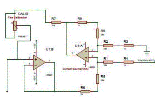
| 4) RTD Current Excitation Circuit: For best linearity, the RTD sensing element requires a stable current reference for excitation. This is implemented in a way shown in fig.2. In this circuit a voltage reference along with two operational amplifiers are used to generate a floating 1 mA current. |
| This is accomplished as follows: |
| The operational amplifier A1 (U1-A) and resistor R1 through R4 for a difference amplifier with a differential gain (GA1) of 1v/v. A 2.5v precision voltage reference is applied to input of this difference amplifier. The output of op-amp A2 (U1-B) serves as the difference amplifier’s reference voltage. The voltage at the output of A1 is shown in eq.1 below; |
| VoutA1= VREF GA1 +Vout2 ---------------- (1) |
| Where; |
| VoutA1 = A1’s output voltage |
| Vout2 = A2’s output voltage |
| VREF = Reference voltage at input |
| GA1 = 1v/v |
| Assuming |
| Vout2= V2, and R7= RREF |
| we get, |
| VRREF= VOUTA1 –V2 |
| VRREF=VREF |
| Where; |
| V2= voltage at A2’s input |
| VRREF= voltage across RREF |
| The current used to bias the RTD assembly (IRREF) is constant and independent of the voltage V2, |
| IRREF=VRREF/RREF |
| IRREF=1mA |
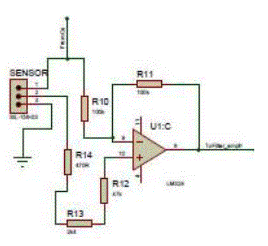
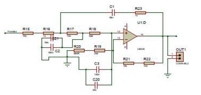
| 5) RTD Signal Conditioning Circuit: The current excitation circuit excites the RTD element. The magnitude of the current source is turned to 1mA or less by adjusting RREF. The RTD signal conditioning path is shown in fig.3 and fig.4 below. |
| The voltage drop across RTD element is sensed by A3 (U1-C), and then gained and filtered by A4 (U1-D). With this circuit a 3 wire RTD element was selected. This configures minimizes error due to wire resistance and wire resistance drift over temperature. In this circuit RTD element equals 100Ω at 0oc. If the RTD is use to sensed the temperature over the range -200oc to 600oc. the resistance produced by the RTD would be between 18.5Ω and 313.7Ω giving a voltage across RTD between 18.5mv and 313.7mv [10]. |
| The error contributed by wire resistance is subtracted from the signal with op-amp A3. The voltage signal at the output of A3 is filtered with 2nd order filter created with A4. It reduces the noise and prevents aliasing of high frequency signals. This filter uses a Sallen-key topology specially designed for high gain [11]. The capacitor divider formed by C1 and C3 improves the filters sensitivity to components variations. The voltage A4’s output is nominally between 0.138v to 2.343v, which is less than VREF (2.5v). This output is given to microcontroller. |
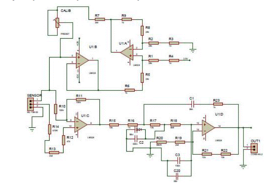
| The complete signal conditioning circuit is shown in fig. 5 below; |
| 6) Controller Section: The analog value of temperature is given to microcontroller PIC16F876A, which has in built A/D convertor. The signal is processed inside the controller and given to display section and relay. |
| 7) Display Section: Since it is essential to display the data recorded from the microcontroller, a liquid crystal display is used. |
| 8) Relay: The output of the microcontroller is also given to relay through ULN2003A driver. The relay remains off until measured temperature reaches to set point. When it exceeds the set point temperature, it become on. |
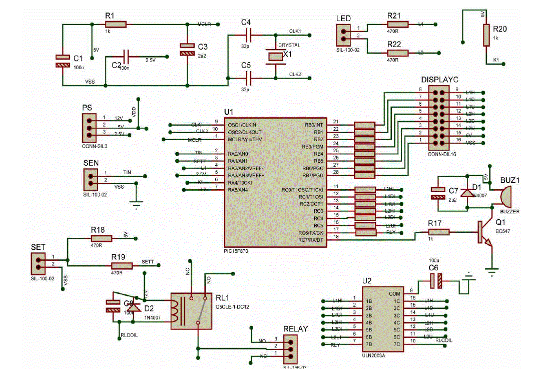
| The complete circuit design of system is shown in fig. 6 below; |
| B. Software Description |
| Software description for the present work is for outline monitoring and controlling and is developed in C language assembly language. |
TESTING AND RESULT
|
| When the fabrication process is completed and all the components have been mounted. Hardware testing was carried out. It was found that all the circuit working properly and perfect and there is no loose connection between the components. |
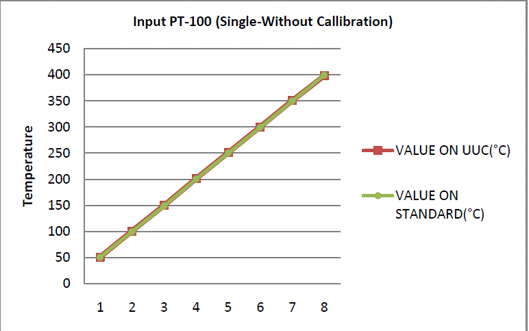
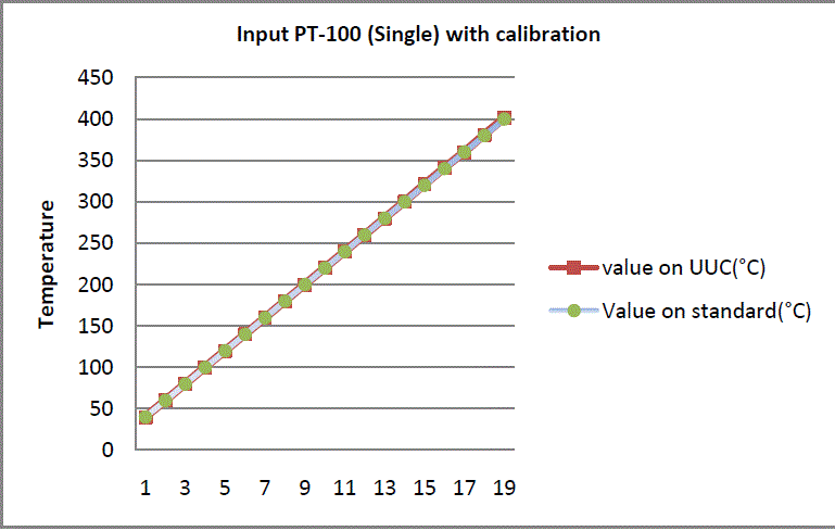
| Later on application testing was done with standard instruments. The result of this testing are tabulated before and after calibration in table1 and table2. UUC stand for unit under calibration. The graph plotted between measured and standard value are shown in fig7 and fig. 8 respectively. |
| These graph shows that reading of measured value is almost identical with standard value. The lower range side of temperature reading is and their slight deviation in upper range of temperature. |
CONCLUSION
|
| In this paper a simple, low cost design of an embedded system foe temperature controller using PIC 16F876A was designed. The sensor element used is Pt-100 RTD. The result of measuring value shows that it response is linear and accuracy is good. The system can be further enhanced by developing it for multi sensor designs, so that there can be choice of sensor as per the requirement and temperature range. Further it can be improve by making an arrangement for automatic control of temperature of source by remote sensor so that system can automatically adjust the temperature as set. |
Tables at a glance
|
 |
 |
| Table 1 |
Table 2 |
|
Figures at a glance
|
 |
 |
 |
 |
| Figure 1 |
Figure 2 |
Figure 3 |
Figure 4 |
 |
 |
 |
 |
| Figure 5 |
Figure 6 |
Figure 7 |
Figure 8 |
|
References
|
- BogdanLevarda, and CristinnBudaciu., “The Design of temperature Control System Using PIC 18F4620”, Proc.ICSTC 2010, 282-286, 2010.
- A.Goswami, T. Bezboruah,T. and K.C.Sarma, ., “Design of an embedded and implementation of an Embedded system for monitoring and controlling the intensity of light”, Proceeding Of the 2008 International Conference on embedded systems and application during July 14-17,2008 at Las Vegas Nevada, USA, Vol.-ESA 2008, pp.117-123.
- A.Goswami, T. Bezboruah, K.C. Sarma., “An Embedded Design for Automatic Temperature Controller”, International Journal of advanced Engineering and Application, Jan 2011.
- A.Goswami, T. Bezboruah,T. and K.C.Sarma,., “Design of an embedded system for monitoring and controlling temperature”, Proceeding ofInternational Conference on emerging technologies and applications in engineering, technology and science during 13th-14th January ,2008,Rajkot, Gujarat, India, Vol.1, pp., 105-110.
- J. Jayapandian and Usha Rani Ravi., “An Embedded Single Chip Temperature Controller Design”, J. Instrum. Society, India, 39(1), 50-54.
- LiminCai. “Temperature Measurement and Control System Based on Embedded Web”, Computer and Information Science, Vol.2.No.2, May 2009.
- “Frequently asked question about RTDs”, Retrieved 2009-09-18.
- “Sensor Technology Sensors”, Retrieved 2009-09-18.
- http:/www.instrumentation sensor.net/hand-held-thermometers.php.
- AN 687, “Precision Temperature Sensing with RTD circuit”, Bonnie. C. Baker, Microchip Technology Inc.
- Kumen Blake., “Transmit Filter Handles ADSL Modern task”, Electronics design, June 1999.
|