ISSN ONLINE(2278-8875) PRINT (2320-3765)
ISSN ONLINE(2278-8875) PRINT (2320-3765)
| R.Elumalai, A.Ramachandran, J.V.Alamelu and Vibha B Raj Department of Instrumentation Technology, MS Ramaiah of Institute of Technology, Bangalore, India |
| Related article at Pubmed, Scholar Google |
Visit for more related articles at International Journal of Advanced Research in Electrical, Electronics and Instrumentation Engineering
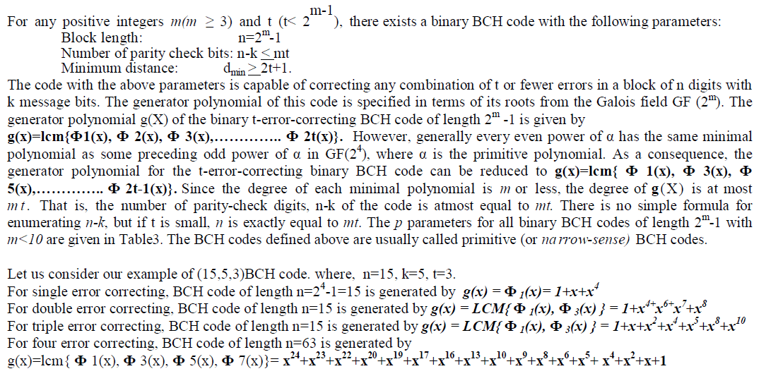
In the present Digital Communication systems, it is highly possible that the data or message get corrupted during transmission and reception through a noisy channel medium. To get the error free communication we need Error correction code. BCH codes invented in 1960s are powerful class of multiple error correction codes with well defined mathematical properties, used to correct multiple random error patterns. The mathematical properties within which BCH codes are defined are the Galois Field or Finite Field Theory. The project proposed is “FPGA implementation of Encoder and decoder for (15, 11, 3) and (63, 39, 4) Binary BCH code using VHDL with multiple error correction”. The digital logic implementation of binary encoding and decoding of multiple error correcting BCH code of length n=15 and n=63 over GF (24) and GF(26)with irreducible primitive polynomials x4+x+1 and x6+x+1 are organized into n-k linear feedback shift register circuits for encoding. Iterative decoding algorithms are used to find the location of error and decode the message bits at receiver side. Two encoders and decoders are designed using VHDL to encode and decode the triple and four error correcting BCH code corresponding to the coefficient of generated polynomial. For implementation Spartan 3 FPGA processor is used with VHDL and the simulation & synthesis are performed using Xilinx ISE 13.2.
Keywords |
| BCH, BCH Encoder, BCH Decoder, FPGA, VHDL, Error Correction, LFSR. |
INTRODUCTION |
| The Information revolution is in full swing, having matured over the last thirty years. It is estimated that there are hundreds of millions to several billion web pages on computers connected to the Internet, depending on whom you ask and the time of day. The google.com search engine listed 1,346,966,000 web pages in its database. Add to that email, FTP transactions, virtual private networks and other traffic, and the data volume swells to many terabits per day. With all these terabits per second flying around the world on copper cable, optical fiber, and microwave links, the question arises: How reliable are these networks? Imagine losing a newspaper story on the wires every four seconds, or 900 stories per hour. Even a small error rate becomes impractical as data rates increase to stratospheric levels as they have over the last decade. To have a reliable communication through noisy medium that has an unacceptable bit error rate (BER) and low signal to noise ratio (SNR), we need to have Error Correcting Codes which is based on proven mathematical formulas. There are many types of error correction codes based on the type of error expected, the communication medium and weather re-transmission, etc. Some of the Error correction codes [3], which are widely used these days, are BCH, Turbo, Reed Solomon, and LDPC. These codes are different from each other in their complexity and implementation [1] [5]. Here, two encoders and decoders are designed using VHDL [6],[8] to encode and decode the triple and quadruple error correcting BCH code corresponding to the coefficient of generated polynomial on FPGA. |
| The structure of this paper is as follows. Section II contains a brief description of the BCH code and generated polynomial. Section III contains Encoder Design for multiple error correction. Section IV contains decoder Design for multiple error correction. Section V contains simulation results and Section VI contains conclusion and possibility of extending the scope of project. |
LITERATURE SURVEY |
| The pioneering work lead by Claude Shannon [2] in 1948 with the significant and breakthrough contribution from coding theorist like Hamming, Peterson, Bose-Ray Chaudhari, Hocquenghem, Reed and Solomon, E.Berlekamp, Massey, G.D.Forney Jr. There exists several coding and error correction in digital communication. Bose-Ray Chaudhari [7] presented binary group codes and its error correcting ability. W.W. Peterson [4] describes the encoder techniques for error correction Bose-Ray chaudari binary group codes. |
| Ernest Jamro [6] used the linear feedback shift register for polynomial division encoder design. The format of the codeword is c(x) = xn-k * i(x) + b(x) and BCH codes are implemented as cyclic code. VHDL implementation and its results have been discussed with reports on recourses used and power consumed. |
BCH CODE |
 |
ENCODER LFSR DESIGN |
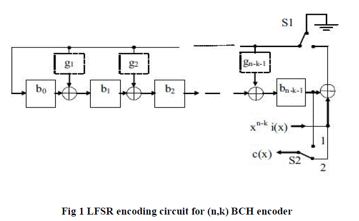
| The Encoder LFSR design used in this project is most commonly used in the modern digital communication system. This encoder LFSR design is almost common to all the BCH code architecture, which uses the linear feedback shift register for polynomial division. |
| The format of the codeword is as follows : |
 |
| BCH codes are implemented as cyclic code. As a result, the logic which implements encoder_LFSR and decoder is controlled into shift register circuits. With the help of cyclic code properties the remainder b(x) can be calculated in the linear (n-k) stage shift register with the feedback connection to the coefficient of generator polynomial. |
| The operation of the encoder_LFSR design is as follows : |
| a) For the clock cycle 1 to k, the original message bits are transmitted without changing its form (during this operation switch s2_in is in position 2), and the linear feedback shift register calculates the parity bits (switch s1_in is on now). |
| b) For cycle k+1 to n, the generated parity bits in the linear feedback shift register are transmitted (switch s2_in is in position 1) and the feedback in the LFSR is switch off (s1_in off). |
| The block diagram of BCH encoder_LFSR consists of three modules as shown in fig.1. |
| - 5 bit Parallel to Serial Shift Register |
| - Encoder_LFSR module - Linear feedback shift register |
| - Serial to Parallel Shift Register |
| In this work, we have designed three error correcting BCH code. The input to the BCH encoder_LFSR is 15- bit message. |
| The BCH encoder_LFSR uses the linear feedback shift register (LFSR) for polynomial division. This division generates redundant parity bits. |
 |
DECODER DESIGN AND ARCHITECTURE |
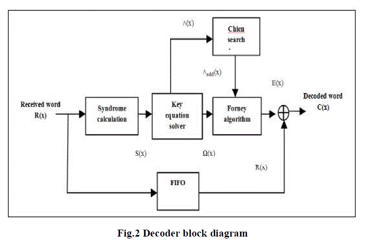
| The BCH decoder has four modules as mentioned below and shown in fig.2: |
| - Syndrome Calculator |
| - Solving the key equation |
| - Error Location |
| - Error Correction |
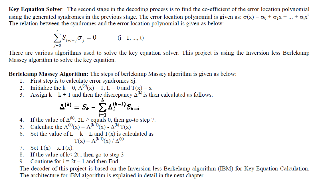
| The implementation and the algorithms used to design the above modules vary with the architectures. The 2nd module, Solving the key equation is the most difficult and complex module as compared to the other modules in respect to the hardware complexity. |
 |
| Syndrome Calculator: The syndrome calculator is the first module at the decoder also, the design of this module is almost same for all the BCH code decoder architecture. The input to this module is corrupted codeword. The equations for the codeword, received bits and the error bits are given in equations as follows. |
| Codeword equation |
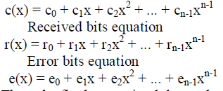 |
| Thus, the final transmitted data polynomial equation is given as be r(x) = c(x) + e(x) . |
| The 1st step at the decoding process is to store the transmitted data polynomial in the buffer register and then to calculate the syndromes sj. The important characteristic of the syndromes is that depends on only error location not on transmitted information. The equation of the syndromes are given as follows: |
| Define the syndromes Sj as |
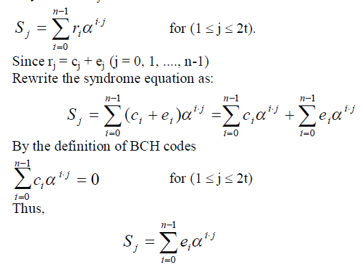 |
| The above equation indicates the output of the syndrome calculator. From the equation it can be observed that the syndromes are depends on only error polynomial e(x), so if there is no error occurs during the transmission then all the generated syndromes will be zero. |
 |
 |
| To locate the roots of the polynomial, chain search block is implemented in hardware for the BCH decoder. The chain search block has a property that the roots going to be a power of α reduce the evolution of the polynomial for every root. So, the use of the chain search block provide the computational benefits of the step, Λ i (j) = Λ i (j-1) αi. This property makes the chain search method more superior then other methods. |
| Decoder Design Architecture: The Decoder design consists of 5 blocks. These blocks are: |
| 1. Parallel to Serial Shifter |
| 2. Syndrome Block |
| 3. Inversion-less Berlekam Massey Block |
| 4. Chain Search Block |
| 5. Error Correction Block |
SIMULATION RESULTS |
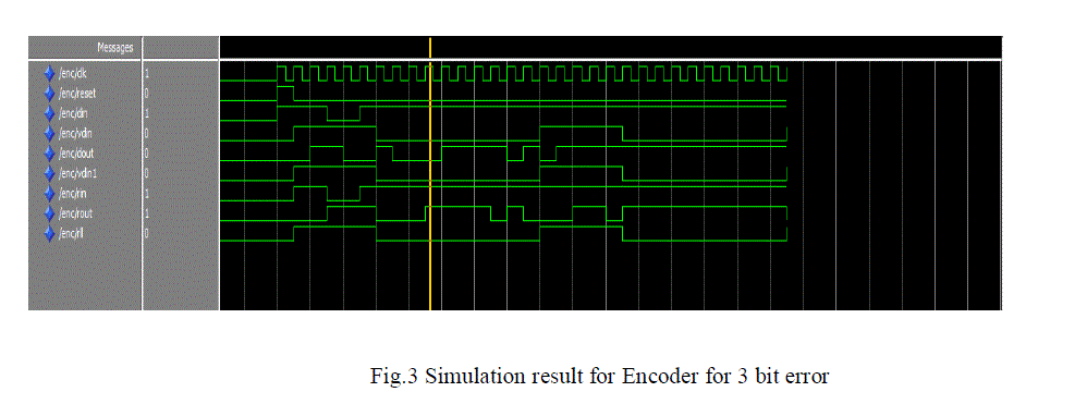
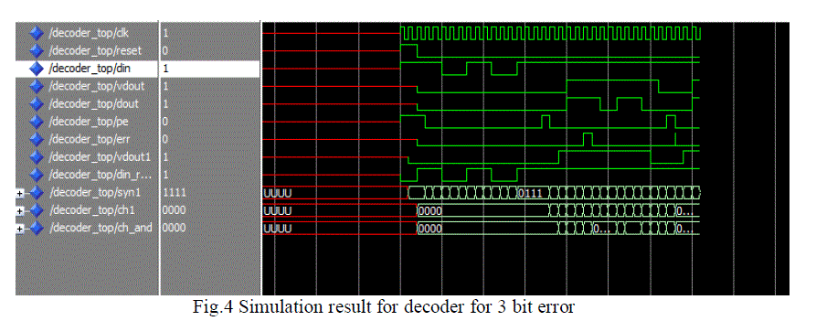
| The simulation results of Encoder and decoder is shown in fig.3 & fig.4. The results are simulated with Xilinx ISE13.2 |
 |
 |
CONCLUSION |
| The result presented from the synthesis and timing simulation, shows the (63, 39, 4) BCH Encoder is more advantageous over the other coding techniques according to speed as a parameter. It can correct 4 errors at the receiver side when the original data is corrupted by the noise. When area is considered then (15, 5, 3) is superior and this can correct only 3 bit error. The redundancy is less and the data rate is more. BCH codes have resulted in excellent error correcting codes among codes of short lengths. They are simple to encode and decode. Due to these qualities, there is much interest in the exact capabilities of these codes. The speed and device utilization can be improved by adopting parallel approach methods. |
References |
|