Keywords
|
| rectangular Microstrip antenna, uniplanar Electromagnetic Band Gap (EBG), bandwidth. |
INTRODUCTION
|
| With the rapid development of wireless field, microstrip antennas became more appealing in antenna community. These antennas are low-profile, light weight, low price compactness. A narrow impedance bandwidth is another limitation of microstrip patch antennas. However, surface waves are, a major drawback for this type of antenna as they lower the antenna efficiency [1-2]. Over the past few years the new techniques have been applied to suppress surface wave propagation, namely periodic structures called the Electromagnetic Band Gap (EBG) structures [3]. EBG structures have attracted a great attention due to their unique characteristics in controlling the propagation of electromagnetic waves in specified frequency bands. This property enables the EBG structures to block the propagation of waves and guide them in a desired direction by forbidding the propagation of EM waves in certain frequency band [4]. Therefore, if the EBG structure is applied to the mobile phone, the undesired electromagnetic waves can be prevented. The features of EBG structures are suppressing unwanted substrate modes and acting as an artificial magnetic ground plane [5]. The EBG structures are also used to improve the antenna performance as radiation patterns and to minimize the side and back lobe levels. An EBG structure is a periodic structure that forbids the propagation of all electromagnetic waves within a particular frequency band called the band gap. These structures provide a simple and effective solution to the problems of surface and leaky waves [6]. Several types of microstrip based EBG structures have been analyzed for variety of applications. |
| In this paper uniplanar EBG cells are loaded on the ground plane of the microstrip antenna to study the performance of the antenna enhance the bandwidth of the conventional Microstrip antenna. |
ANTENNA AND EBG STRUCTURE
|
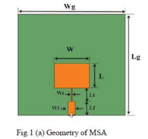
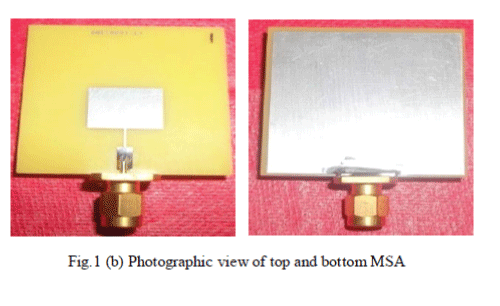
| In this paper a conventional microstrip antenna has been designed for 6GHz.The antenna is designed on FR4 with dielectric constant εr = 4.4 and with the height of h=1.6mm with the width of W=11.33mm and the length L=15.24mm respectively. The antenna is feed by stripline fed Lf50=6.18mm & Wf50=3.06mm to match the impedance and quarter wave transformer Lt=4.92mm & Wt=0.5mm is used and ground plane Lg=40mm and Wg=40mm is considered for the design. The geometry is as shown in Fig.1 (a) and the photographic view of the conventional MSA antenna is shown in the Fig.1 (b). |
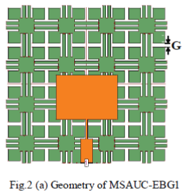
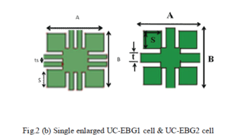
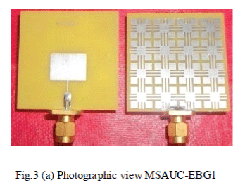
| Further the study is carried out by replacing the conducting ground plane of the MSA with high impedance surface UC-EBG cells for bandwidth enhancement by keeping all the parameter of the radiating patch and feeding technique constant. The fig.2 (a) shows the antenna with EBG on the ground plane. The geometry of the single enlarged UC-EBG1 cell is shown in the Fig. 2(b). There are 4x4 UC-EBG cells with dimension of 9mmx9mm and a gap between UC-EBG G=0.75mm, the other parameters s=3mm, t=2mm and the slot ts=1mm at the center of the t. The gap between s and t is g=0.5mm and a single enlarged unit of UC-EBG cell is as shown in Fig. 2(b). The photographic view of top and bottom of antenna MSAUC-EBG1 is as shown in Fig. 3(a). |
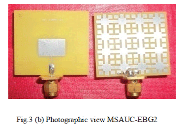
| In MSAUC-EBG2 the parameter there are 4x4 UC-EBG cells with dimension of 9mmx9mm and gap G=0.75mm and s=3mm are kept constant as that in MSAUC-EBG1. The parameter ‘g’ is varied from 1mm to 0.5mm and‘t’ is varied by removing slot ‘ts’. The geometry of the single enlarged unit of UCEBG2 is as shown in the Fig.2 (b.) Also the photographic view of the antenna with MSAUC-EBG2 cells is shown in Fig. 3(b). |
EXPERIMENTAL RESULTS
|
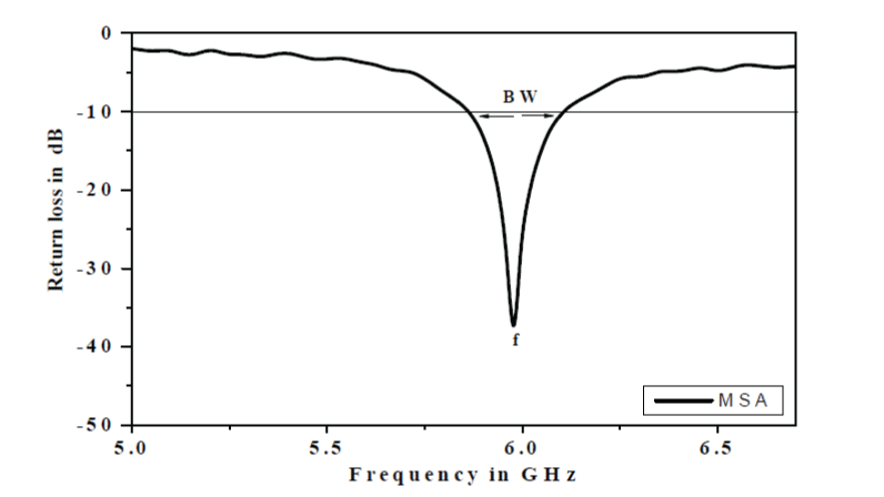
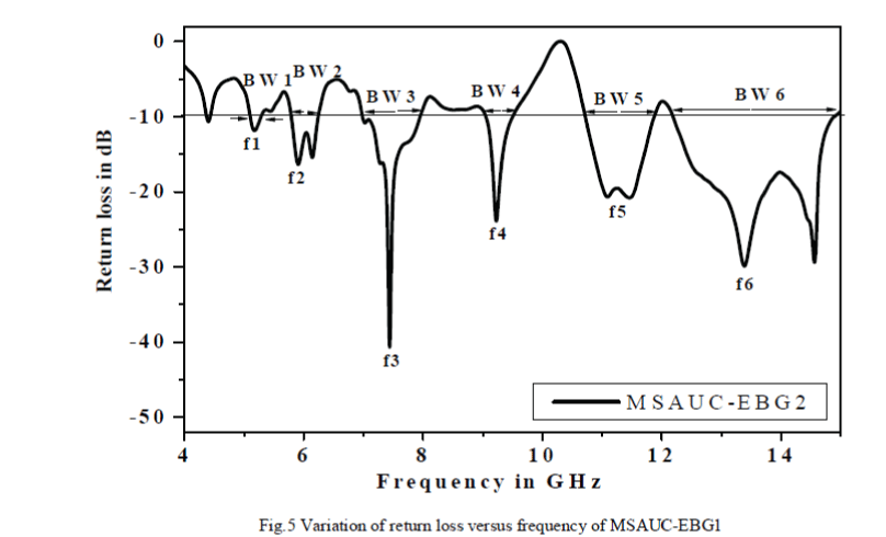
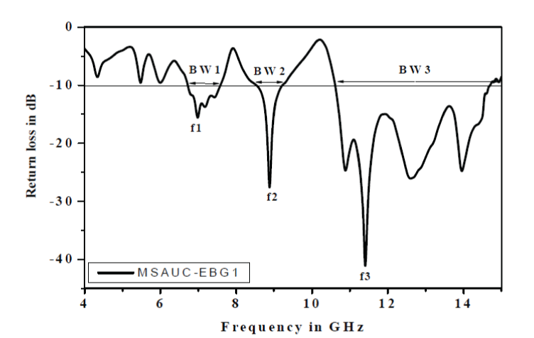
| The characteristics of proposed antennas have been experimentally measured with Vector Network Analyzer (Rohde & Schwarz, Germany make ZVK model 1127.28651).The variation of return loss versus frequency characteristics of proposed antennas, MSA, MSAUC-EBG1 & MSAUC-EBG2 are shown in Fig.4, 5 & 6. From the Fig.4, it is found that, the antenna MSA resonates at f=5.99GHz and gives a bandwidth of 4.81%. From this Fig.5,it is clear that by loading & UC-EBG cells on the ground plane there is enhancement of bandwidth of the rectangular Microstrip antenna i.e., MSAUC-EBG1 is giving multifrequency with increase in bandwidth. It is found that, the antenna MSAUC-EBG1 gives a three bands with f1 = 6.99GHz, f2 = 8.86GHz, f3= 10.87GHz and the overall bandwidth of MSAUC-EBG1is 57.11%.. Similarly MSAUC-EBG2 operates between 5GHz to 14GHz gives six bands with f1=5.19 GHz, f2=5.90GHz, f3=7.43GHz, f4=9.22GHz, f5=11.10GHz, f6=13.41GHz, so the overall bandwidth measured for MSAUC-EBG2 is 60.64%.The proposed antennas are compared with conventional MSA. All the results are reported in table1. |
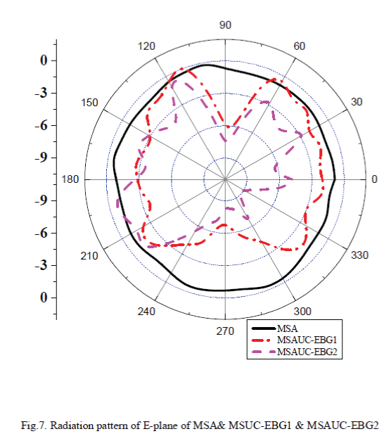
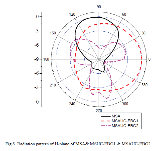
| For the measurement of radiation pattern, the antenna under test (AUT) i.e., the proposed antennas and standard pyramidal horn antenna are kept in far field region. The AUT, which is the receiving antenna, is kept in phase with respective transmitting pyramidal horn antenna. The power received by AUT is measured from −00 to +3600 with the steps of 100. The E-plane radiation patterns of conventional MSA, MSAUC-EBG1 & MSAUC-EBG2 are measured and are shown respectively in Fig.7. Fig.8 gives H-plane patterns of proposed antennas. From these figures it is clear that, there is reduction in back lobes of the MSAUC-EBG1 and MSAUC-EBG2. |
CONCLUSIONS
|
| A microstrip antenna with enhanced bandwidth using a uniplanar electromagnetic band gap structure design based on EBG technique has been presented. The proposed design helps to achieve multiband and enhancement in the bandwidth of 60.64% after loading UC-EBG cells on the ground plane, which makes the antenna useful for wireless applications. |
ACKNOWLEDGMENT
|
| The authors would like to convey thanks to the department of science & technology (DST) government of India, New Delhi, for sanctioning vector Network analyzer to this department under FIST project. |
Tables at a glance
|
 |
| Table 1 |
|
Figures at a glance
|
 |
 |
 |
 |
 |
| Figure 1a |
Figure 1b |
Figure 2a |
Figure 2b |
Figure 3a |
 |
 |
 |
 |
 |
| Figure 3b |
Figure 4 |
Figure 5 |
Figure 6 |
Figure 7 |
 |
| Figure 8 |
|
References
|
- M.S. Alam, M.T. Islam and N. Misran “Design Analysis of an Electromagnetic Band Gap Microstrip Antenna”, American Journal ofApplied Sciences 8 (12): pp 1374-1377, 2011.
- Anamika Singh, Aadesh Arya & Sanjay Sharma “High Gain of C Shape Slotted Microstrip Patch Antenna for Wireless System”,International Journal of Applied Engineering Research, Vol.7, No.11 (2012).
- Aijaz Ahmed, Yogesh “ Electromagnetic Band Gap Coupled Microstrip Antenna for UWB Applications”, IOSR Journal of Electronicsand Communication Engineering (IOSRJECE) Vol. 2, Issue 6 (Sep-Oct 2012), pp 01-03.
- O.Rangarao, M. Grace Priscilla, D.N. Bhushan Babu, J. Naveen, T. Vijay Sundeep, E. Raghu “Effect of EBG Presence on Elliptical PatchAntenna”, International Journal of Advanced Research in Computer and Communication EngineeringVol. 2, Issue 4, April 2013 pp 1892-1895.
- Gaurav Kumar Sharma, Narinder Sharma “ Improving the Performance Parameters of Microstrip Patch antenna by using EBG Substrate”IJRET: International Journal of Research in Engineering and Technology Volume: 02 Issue: 12 Dec-2013, pp 111-115.
- Chandan Kumar Ghosh, Biswarup Rana, S. K. Parui “Performance Enhancement of Microstrip Patch Antenna Array with EBG Structure”, IJECT Vol. 2, Issue 4, Oct. - Dec. 2011, pp 280-283.
|