The photovoltaic power generation system is used widely in the residential and industrial purpose day by day. The conventional methods used for the energy conversion need to be improved due to some drawbacks. Several researches are going on in the direction of cost and efficiency, the flyback DCM inverter has been emerged out as a low cost solution. However, the flyback DCM inverter operated under continuous conduction mode shows a better efficiency at low cost. Unfortunately, it causes unintended distortions in the output voltage and current. When connected to the grid under non-linear loads conditions it cause the voltage instability. In this paper, an unfolding type H-bridge switching techniques are introduced in order to reduce those drawbacks. The simulation are done on the basis of non-linear load conditions . The output current and voltage distortions are reduced by the unfolding type H-bridge switching techniques.
Keywords |
| Distributed power generation, Flyback inverter, Photovoltaic AC module systems, Solar energy,
Unfolding H-bridge. |
INTRODUCTION |
| Nowadays, distributed power generation in residential areas using solar panels, is well accepted and also supported by
recent developments in building integrated photovoltaic systems as well as micro grid systems. However, when PV
panels are connected in series to feed a string inverter with a global maximum power point tracker, a considerable
power loss due to modular mismatches caused by both varying panel orientations and shading would occur. A major
approach to solve this issue has been to package the PV panel with a module-integrated inverter [5], called an ac
module, which directly serves the grid. Though requiring a large number of dc–ac conversion stages, the approach
allows for easy plug and play system expansion. Also, only ac cable wiring is required, which simplifies the
installation. |
| The acceptability of an ac module depends on its efficiency, cost effectiveness, and reliability. Three major trends are
noted in the study of inverter topologies for this application. The first is the use of a transformer less inverter [3] that is
motivated by the benefits of reduction in size and cost and also by possible efficiency improvement. However, the
limited voltage boosting capability of such an inverter unit prevents the use of this technology in universal grid voltage
range applications. Another trend is focused on an isolated cascaded scheme that includes one or more dc voltage
boosting stage and a usual full bridge PWM inverter. Compared to other isolated inverters, this type of inverter has by
far the highest reported efficiencies. Also, the power decoupling by the electrolytic capacitor can be replaced by a
higher voltage film capacitor with longer life span. However, the consequence paid for this approach is more
component count and hence higher cost. |
| Considerations of reducing the cost have led to a third approach based on an unfolding type inverter. Here, the dc–dc
converter performs the voltage boosting, isolation, and output current shaping and then followed by a low-frequency
unfolding stage. A simple overall system of flyback inverter having center-tapped secondary windings is often adopted.
However, in this scheme, the flyback is operated in the discontinuous conduction mode emerged as a low cost solution.
The operation of the flyback inverter under discontinuous conduction mode which is hard to increase power conversion
efficiency, due to its large RMS and peak current values. The high current stress across the switches leads to lower
efficiencies. This is mainly true in low voltage and high-current applications such as the ac module under concern.
Even though higher efficiency can be achieved under continuous conduction mode, the [9] shows the designing of the
flyback inverter under continuous conduction mode, the output current and voltage stresses are reduced. But it shows some output current and voltage distortions when connected with grid. During the non-linear load operation the high
voltage stresses across the switches and voltage instability are occurred. So some specialized techniques have to be
made to overcome these problems. The flyback inverter has an unfolding H-bridge design configuration will be
presented. The major objective of the present work is to reduce the distortion of output current and voltage of the CCM
flyback inverter by the unfolding H-bridge switching, In the proposed method the current and voltage stresses are been
reduced because of the four switches. The circuit is operated under non-linear load in order to investigate its stability.
The LC filter reduces the ripples on output and the level of output voltage is increased there by the efficiency can
increase. |
FLYBACK CCM INVERTER |
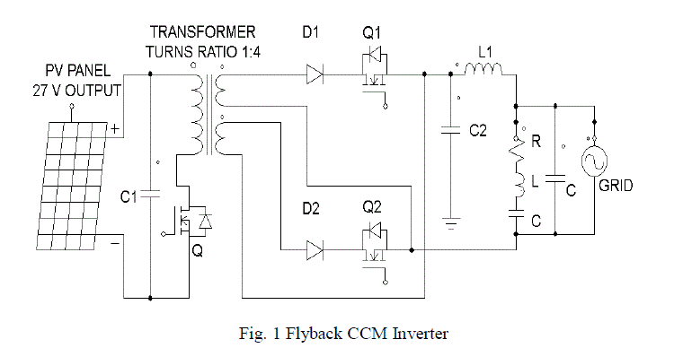
| The topology is the same as that used in a flyback ac module operating in discontinuous conduction mode and consists
of an input capacitor C, a flyback dc-dc converter with two secondary windings together with a waveform unfolding
arrangement as shown in the Fig .1. Secondary side switches Q1 and Q2 are turned ON and OFF respectively to
generate the ac output during the positive and negative half cycles. In each half cycle, the inverter operates as a dc-dc
flyback converter with the average output current shaped as a half sinusoid at the line frequency. The simple overall
system of a flyback inverter with center tapped secondary windings is often adopted. However, the flyback is operated
in the discontinuous conduction mode, which resulting in high current stress and lower efficiencies. |
 |
| When operated in continuous conduction mode, a flyback converter has lower peak currents and hence higher
efficiencies. This has been exploited before in both dc-dc power conversion and ac-dc power factor correction
applications. However, the control towards the output current transfer function in a flyback CCM converter has a right
half plane zero, which causes complexity in controlling the output current of the converter effectively. The flyback
operated under CCM mode of operation will possess a higher efficiency than DCM operation. But when it is connected
with the grid, it shows some unintended distortions in the output current and voltage. The grid may contains the nonlinear
loads like power electronic equipments will make some voltage instability. |
| The output voltage of the flyback converter operated in CCM mode is given by |
 |
| where D is the duty cycle of the switch, |
| n is the transformer turns ratio. The output voltage of the flyback converter operated in DCM mode is given by |
 |
| A. Designing Steps |
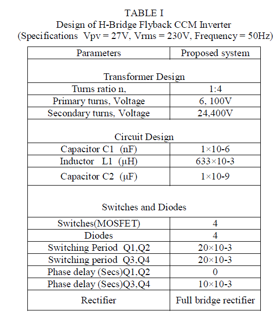
| Step 1: Identify PV panel specifications. The voltage Vpv and current I pv values given by the manufacturer
correspond to MPP and vary with solar irradiance and temperature. For design purposes, a constant Vpv is used, the
current change leads to the variation of power. In core based transformers, the first step is to select the core type and
size in order to meet the given power requirements. |
| Step 2: Choose a switching frequency fs considering the trade-off between the switching losses and the transformer
size. |
| Step 3: The selection of the turn’s ratio, n, so as to estimate the maximum stress across on the switch SW1 in the off
state, ignoring the leakage inductance spike. The maximum voltage stress on the switch, SW1, at Vin_max, by
considering the 1volt drop across the flyback diode is given as. |
 |
| Step 4: Since no dead time exists, as was the case of DCM, the total time period ‘T’ is the summation of the Ton and
Toff. The duty cycle ratio D in continuous mode of operation is obtained as follows. |
 |
| Step 5: From the given output power ‘Po’, the current at the centre of the ramp of the secondary current pulse can be
obtained by knowing the duty cycle and output voltage. |
 |
| Step 6: By assuming the energy efficiency to be 80%, the current at the centre of the ramp of the primary pulsed current
can be obtained from 2.14 and 2.15. |
 |
 |
UNFOLDING H-BRIDGE CONFIGURATION |
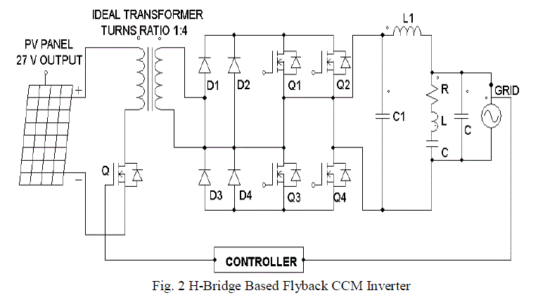
| The proposed circuit diagram is shown in Fig. 2, which consists of the unfolding type H-bridge. The flyback converter
used in this circuit consisting of two stages. The first stage includes the conversion of the DC output of PV module to
rectified-DC synchronized with grid voltage. Also, the shape of output current of the flyback inverter is determined by
the switching of flyback converter. The second stage is about the unfolding H-bridge stage determines the direction of
output current to be matched with grid voltage polarity. The unfolding switches Q1 and Q4 are turned-on and the Q2
and Q3 are turned-off during the positive period of grid voltage. During the negative period, the unfolding switches are
operated oppositely. |
 |
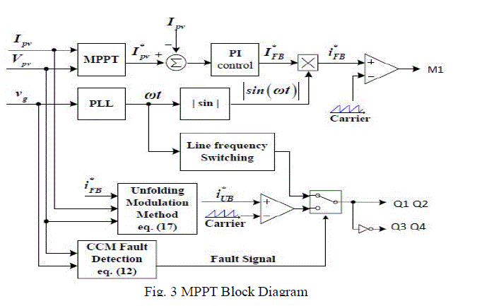
| As the power conversion systems for photovoltaic applications have to track the MPPT. In the flyback inverter shown
in Fig. 2, the maximum power point tracking can be performed by peak point variation of the switching reference.
Thus, MPPT determines the amplitude of output current reference. Because of the unfolding H-bridge determines only
the direction of the output current conventionally, the flyback converter stage covers the output current shaping as well
as the MPPT. Thus, the flyback converter switching is determined by rectified sinusoidal reference which synchronized
with the phase of grid voltage. |
| A. H-Bridge switching technique |
| The flyback inverter used in the proposed system comprises of two stages, the flyback converter stage and unfolding Hbridge,
while the conventional flyback inverter looks like a single-stage power conversion system. The flyback inverter
composed of two stages has some advantages to get higher power conversion efficiency due to its H-bridge based
unfolding method, while the single stage configured flyback inverter is a cost effective solution for photovoltaic AC
module systems. In the single-stage flyback inverter a three winding transformer is required. It means that larger
winding area is required even though the turns-ratio of the transformer, n, is same in the conventional method and
proposed method. |
| Thus, the total loss of transformer used in single-stage flyback inverter can be much larger than that in the two-stage
flyback inverter. On the other hand, the major difference between the unfolding H-bridge and the conventional
unfolding stage is appeared in the voltage stress of the secondary switching devices. In conventional method the
maximum voltage of the secondary active switches Q1 and Q2 is equal to 2Vg(pk), where Vg(pk) is the peak value of
the grid voltage. Actually, the required voltage rating of the secondary active switches can be higher than 2Vg(pk) due
to the oscillation or ringing of the secondary current. |
| In case of the 220Vrms grid applications, the voltage rating of secondary switches recommended to be higher than
800V. Unfortunately, higher voltage rating of the switching devices causes larger conduction losses. The unfolding Hbridge
requires four active switching devices as shown in Fig .2. However, the maximum voltage of the unfolding
switching device can be a half of that of the conventional unfolding stage. Thus, in the power conversion efficiency
point of view, the unfolding H-bridge can be more useful solution. |
| The output current of flyback inverter ig is in Equation 3.1 as follows, |
 |
| where Lf is filter inductance, VLf is voltage of the filter inductor Lf and Vg is the grid voltage. During the positive
period of grid voltage, the voltage of filter capacitor, VCf, is equal to link voltage, VCs, due to the unfolding bridge
operation. If the voltage drop of unfolding H-bridge is
neglected, the Ig can be written in Equation 10 |
 |
| Consequently, it is obvious that the output current can be controlled by the link voltage, VCs, under the normal
unfolding bridge operation. |
| B. Controller |
| The MPPT controller has adopted in this proposed circuit as shown in Fig. 3.The voltage stability analysis done on the
basis of the MPPT controller. The output has feed back to the MPPT controller. The non-linear load has introduced.
The output voltage stability may changes. It may compare with a reference value like triangular wave to generate the
compensation wave may control the flyback switch. The modelling of the MPPT controller has done on the basis of the
MPPT algorithm. Therein an MPPT controller it may generate compensation signal by a PI controller with the PV
panel voltage and current. Even if there is any change in the output occurs, that signal may compare with the reference
signal. |
 |
SIMULATION RESULTS AND DISCUSSION |
| The conventional Flyback inverter shows a voltage dip in the initial stage. The voltage and current distortions are
occurred in some stages as shown in the Fig .5. Those drawbacks have been reduced by the unfolding H-bridge
switching techniques as shown in the Fig .6. As in the non-linear load conditions the proposed systems shows a better
voltage stability. The linear transformers are used instead of the multi winding transformer. The losses due the
increased number of switches are negligible because of the reduced transformer losses on the other side. |
| A. Based on Closed Loop (With MPPT Controller) |
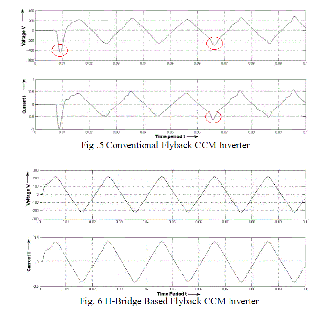 |
| The conventional flyback CCM inverter as shown in Fig. 5, when subjected to non linear load operation with MPPT
controller shows an initial voltage dip and output distortions at some points. It shows a maximum 400V in the initial
stage then it attains the stable state. It gives 230V voltage and current .4A. |
| The proposed H-bridge flyback inverter as shown in Fig. 6, when subjected to non linear load operation with MPPT
controller doesn’t shows any voltage dip and distortions in the output as present in the conventional system. It shows a
230 V voltage and .4A current. If any voltage fluctuations or any other disturbances are occurred, the voltage and
current stresses across the switches will not increase as there exists 4 switches. The efficiency is better than the
conventional system. |
| B. FFT Analysis for THD Calculation |
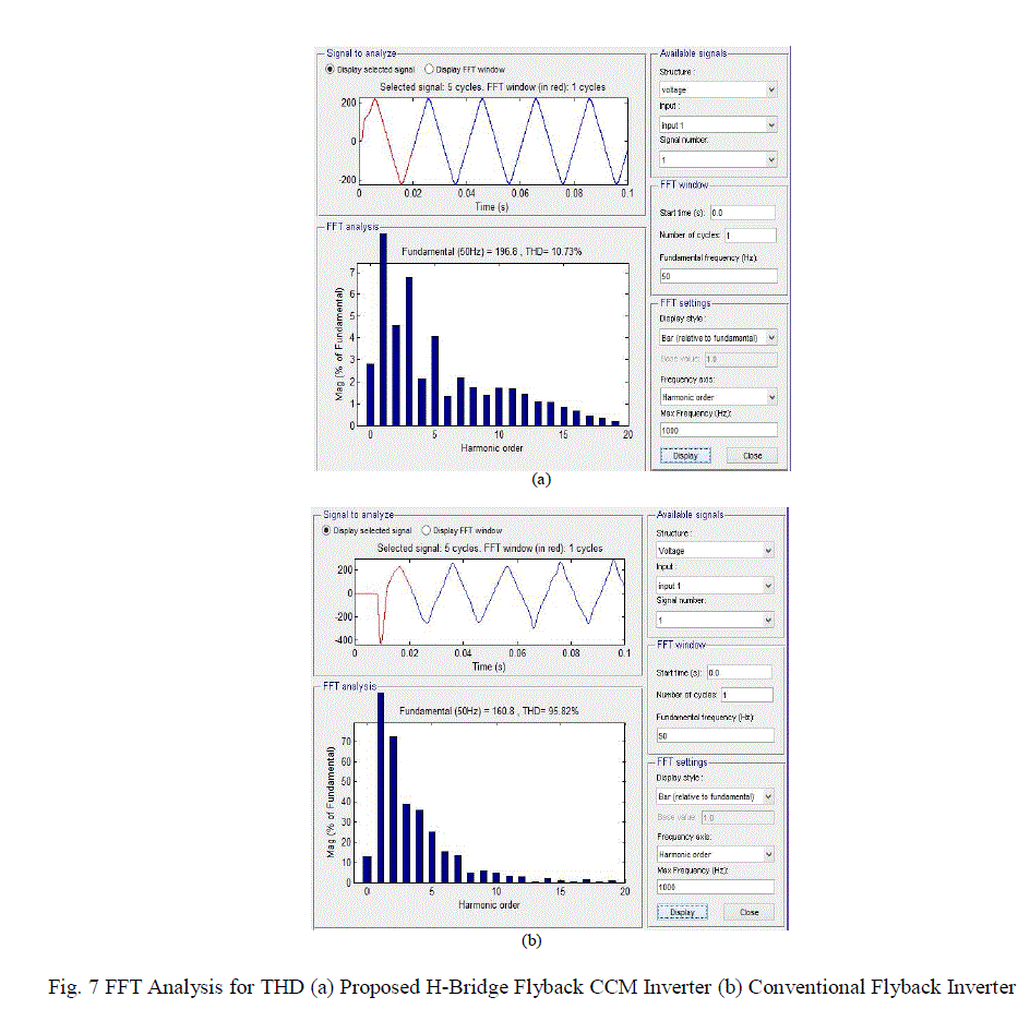
| The Fast Fourier Transform analysis are done are done for the THD calculation. When comparing the two values
obtained, it shows a large difference between the conventional system and proposed system. The conventional system
had shown 95.62% as shown in the Fig.7 (b). The proposed system had shown 10.73% as shown in the Fig.7 (a). From
the results, it can be validated as the increased number of switches doesn’t make any deviation in the overall output and
it gives better efficiency than the conventional system. |
| The conventional system shows the THD more is only due to the increased current stress across the switches when the
load fluctuation occurs. Even it contains a half bridge having 2 switches. The proposed H-Bridge contains four number
of switches. Which having a withstand capacity under the non linear load conditions. The FFT analysis for two systems
and the output showing better results over the conventional method. |
 |
CONCLUSION |
| In this paper, the flyback CCM inverter composed of H-Bridge switching technique is applied. The flyback DCM
inverter operated under CCM has been recognized as an attractive solution for grid connected PV-AC module system
due to its simple controller and circuit configuration. The conventional system shows unintended distortions in the
output current and voltage due to the high voltage stresses across the switches. The proposed system uses 4 switches in
order to reduce the stresses. When the conventional system and the proposed systems are connected to grid under non
linear load conditions, the proposed system shows a better efficiency than the conventional system. The simulations are
done on the basis of non linear load conditions. The proposed system has reduced the distortions present in the output.
The THD calculations are done by using the FFT analysis, the proposed system shows a large reduction when
compared with the conventional system. |
References |
- S. B. Kjaer, J. K. Pedersen, and F. Blaabjerg, âÃâ¬ÃÅA review of single-phase grid-connected inverters for photovoltaic modules,âÃâ¬Ã in IEEE Trans. Ind. Appl., vol. 41, no. 5, pp. 1292âÃâ¬Ãâ1306, 2005.
- T. Shimizu, K. Wada, and N. Nakamura, âÃâ¬ÃÅA flyback-type single phase utility interactive inverter with low-frequency ripple current reductionon the DC input for an AC photovoltaic module system,âÃâ¬Ã in Proc. IEEE 33rd Annu.Power Electron.Spec. Conf. (PESC), 2002, vol. 3, pp. 1483âÃâ¬Ãâ1488, 2002.
- Takashi Hirao, Toshihisa Shimizu Mutsuo Ishikawa, Kiyoto Yasui, Japan âÃâ¬ÃÅA Modified Modulation Control of a Single-Phase Inverter withEnhanced Power Decoupling for a Photovoltaic AC Module,âÃâ¬Ã in EPE 2005 âÃâ¬Ãâ Dresden, ISBN : 90-75815-08-5, 2005.
- Ahmed Mohamed Salamah, Stephen J. Finney, and Barry W. Williams, âÃâ¬ÃÅSingle-Phase Voltage Source Inverter With a Bidirectional Buck-Boost Stage for Harmonic Injection and Distributed GenerationâÃâ¬Ã in IEEE Transactions on power electronics, vol. 24, no. 2, 2009.
- Bader N. Alajmi, Khaled H. Ahmed, Senior Member, IEEE, Grain Philip Adam, and Barry W. Williams,(2013), âÃâ¬ÃÅSingle-Phase Single-StageTransformer less Grid-Connected PV System,âÃâ¬Ã in IEEE Transactions on power electronics, vol. 28, no. 6.
- Pengwei Sun, Student Member, IEEE, Chuang Liu, Student Member, IEEE, Jih-Sheng Lai, Fellow, IEEE, and Chien-Liang Chen, Member,IEEE, âÃâ¬ÃÅCascade Dual Buck Inverter With Phase-Shift Control,âÃâ¬Ã in IEEE transactions on power electronics, vol. 27, no. 4, 2012.
- Anastasios C. Nanakos, Emmanuel C. Tatakis, Member, IEEE, and Nick P. Papanikolaou, Senior Member, IEEE, âÃâ¬ÃÅA Weighted-Efficiency-Oriented Design Methodology of Flyback Inverter for AC Photovoltaic Modules,âÃâ¬Ã in IEEE Transactions on power electronics, vol. 27, no. 7,2012.
- Jong-Hyun Lee, Joung-Hu Park, Member, IEEE, and J. H. Jeon, âÃâ¬ÃÅSeries-Connected ForwardâÃâ¬ÃâFlyback Converter for High Step-Up PowerConversion,âÃâ¬Ã in IEEE Transactions on power electronics, vol. 26, no. 12, 2011.
- Young-Ho Kim, Young-HyokJi, Jun-Gu Kim, Yong-Chae Jung, and Chung-Yuen Won, âÃâ¬ÃÅA New Control Strategy for Improving WeightedEfficiency in Photovoltaic AC Module-Type Interleaved Flyback Inverters,âÃâ¬Ã in IEEE Transactions on power electronics, vol. 28, no. 6, 2013.
- Yanlin Li, Student Member, IEEE, and Ramesh Oruganti, Senior Member, IEEE, âÃâ¬ÃÅA Low Cost Flyback CCM Inverter for AC ModuleApplication,âÃâ¬Ã in IEEE Transactions on power electronics, vol. 27, no. 3, 2012.
- Young-HyokJi, Doo-Yong Jung, Jae-Hyung Kim1, Tae-Won Lee, and Chung-Yuen Won, âÃâ¬ÃÅA Current Shaping Method for PV-AC ModuleDCM-Flyback Inverter under CCM Operation,âÃâ¬Ã in 8th International Conference on Power Electronics - ECCE Asia, The ShillaJeju, Korea,2011.
- F. Schimpf, and L. E, Norum, âÃâ¬ÃÅGrid connected Converters for Photovoltaic, State of the Art, Ideas for Improvement of TransfomerlessInvertersâÃâ¬ÃÂ, in Nordic Workshop on Power. Ind. Electronics, 2008.
- S. J. Strong, J. H. Wohlgemuth, and R. H. Wills, âÃâ¬ÃÅThe AC photovoltaic module is here!âÃâ¬ÃÂ, in National renewable energy laboratory and sandianational laboratories photovoltaics program review meeting, AIP Conf. Proceedings, vol. 394, pp. 867-871, 1997.
- Q. Li and P. Wolfs, âÃâ¬ÃÅA Review of the Single Phase Photovoltaic Module Integrated Converter Topologies with Three Different DC LinkConfigurationsâÃâ¬ÃÂ, in IEEE Trans. On Power Electronics., vol. 23, no. 3, pp.1320-1333, 2008.
- SaravanaSelvan. D, Faculty of Engineering and Computer Technology, AIMST University, Bedong- 08100,kedah, Malaysia, âÃâ¬ÃÅModeling andSimulation of Incremental Conductance MPPT Algorithm for Photovoltaic Applications,âÃâ¬Ã in International Journal of Scientific Engineeringand Technology (ISSN : 2277-1581) Volume No.2, Issue No.7, 2013.
|