Keywords
|
| Induction Motor, Multi Level Inverter, Total Harmonic Distortion, PWM Technique |
INTRODUCTION
|
| Majority of industrial drives use ac induction motor because these motors are rugged, reliable, and relatively inexpensive. Induction motors are mainly used for constant speed applications because of unavailability of the variablefrequency supply voltage But many applications need variable speed operations. Historically, mechanical gear systems were used to obtain variable speed. Recently, power electronics and control systems have matured to allow these components to be used for motor control in place of mechanical gears. Present day drive types are the Induction motor drives with voltage source inverters. Also the voltage waveforms of traditional two level inverter fed Induction motor shows that the voltage across the motor contains not only the required “fundamental” sinusoidal components, but also pulses of voltage i.e. “ripple “voltage. The recent advancement in power electronics has initiated to improve the level of inverter instead increasing the size of filter. The total harmonic distortion of the classical inverter is very high. The performance of the multilevel inverter is better than classical inverter. In other words the total harmonic distortion for multilevel inverter is low. The total harmonic distortion is analyzed between multilevel inverter and other classical inverter. A nine level inverter consists of a series of H-bridge inverter units connected to three phase induction motor. The general function of this multilevel inverter |
| Power electronic devices contribute with an important part of harmonics, such as power rectifiers, thyristor converters and static var compensators. Even updated pulse-width modulation (PWM) techniques used to control modern static converters such as machine drives, power factor compensators, do not produce perfect waveforms, which strongly depend on the semiconductors switching frequency. |
MULTI LEVEL INVERTER
|
| It may be easier to produce a high power, high-voltage inverter with the multilevel structure because of the ways in which device voltage stresses are controlled. Increasing the number of voltage levels in the inverter without requiring higher ratings on individual devices can increase the power rating. The unique structure of multilevel voltage source inverters allows them to reach high voltages with low harmonics without the use of transformers or series connected synchronized switching devices. As the number of voltage levels increases, there is more decrease in harmonic content of the output voltage waveform. Multilevel inverters offer a low total harmonic distortion (THD) for output voltage, high efficiency and power factor. |
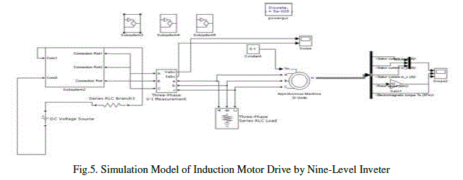
| The block schematic of multilevel inverter fed three phase induction motor is as shown in Fig.5. |
 |
| The complete system will consist of two sections; a power circuit and a control circuit. The power section consists of a power rectifier, filter capacitor, and three phase diode clamped multilevel inverter. The control circuit of the proposed system consists of three blocks namely microcontroller, opto-coupler and gate driver circuit. Basically, there are three kinds of multilevel inverters, these classification are explained in next section. |
CLASIFICATION OF MULTI LEVEL INVERTER
|
| 1. Neutral point clamped inverter (NPC) |
| The neutral point clamped topology is also known as diode clamped topology. The main advantage of the NPC topology is that it requires only one DC source similar to two- level inverter, and gives better performance. With the increase in level ‘n’, not only the number of clamping diodes increases but also the problem of ensuring the DC-link balance becomes more severe. |
 |
| 2. Flying Capacitor Topology (FC) |
| It is also known as capacitor clamped topology. For this topology ‘n’ can take any integer value similar to NPC topology. The voltage clamping is done by using capacitors floating with respect to the earth potential. |
 |
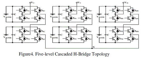
| 3. Cascaded H-bridge Topology (CHB) |
| In this topology the H-bridges are cascaded in every phase. With the increase in H- bridges in a phase, the output voltage waveform tends to be more sinusoidal. In n-level topology, (n-1)/2 identical H- Bridges are used in every phase. There must be a separate DC source for the DC bus of every individual H-bridge. |
 |
NINE LEVEL CONVERTER & INDUCTION MOTOR MODEL
|
| Nine level inverter consists of a series of diode clamped inverter units connected to three phase induction motor. The general function of this multilevel inverter is to synthesize a desired voltage from several dc sources. The ac terminal voltages of each bridge are connected in series. This configuration is useful for constant frequency applications such as active front-end rectifiers, active power filters, and reactive power compensation. |
| This paper makes an overview to find the various induction motor drive configurations used in industry. The various control strategies used to improve drive efficiency and various inverters used to control the motor speed, reduce torque ripple, current ripple and reduce harmonic. The steady-Slate model and equivalent circuit developed in earlier selections are useful for studying the performance of the machine in steady state. The dynamic model considers the instantaneous effects of varying voltages/current. Stator frequency, and torque disturbance. The dynamic model of the induction motor is derived by using a two-phase motor in direct and quadrature axes. This approach is desirable because of the conceptual simplicity obtained with two sets of windings. One on the stator and the other on the rotor. The equivalence between three phase and two phase machine model is derived from simple observations and this approach is suitable for extending it to model an n-phase machine by means of a two-phase machine. The speed of the synchronously rotating reference frame model is: ωc =ωs =Stator supply angular frequency/rad/sec and the instantaneous angular position is Ãâè- C=ÃâèS=ωst and the electromagnetic torque for basic Induction Motor is given as: |
 |
MODULATION TOPOLOGIES FOR MULTILEVEL INVERTERS
|
| Mainly the power electronic converters are operated in the “switched mode”. Which means the switches within the converter are always in either one of the two states - turned off (no current flows), or turned on (saturated with only a small voltage drop across the switch). To control the flow of power in the converter, the switches alternate between these two states (i.e. on and off). This happens rapidly enough that the inductors and capacitors at the input and output nodes of the converter average or filter the switched signal. The switched component is attenuated and the desired DC or low frequency AC component is retained. This process is called Pulse Width Modulation (PWM), since the desired average value is controlled by modulating the width of the pulses. To achieve the greatest possible attenuation of the switching component, it is generally desirable that the switch frequency fc is high — many times the frequency of the desired fundamental AC component f1 seen at the input or output terminals. |
| No frequency components below the fundamental frequency (commonly referred to as sub-harmonics) will exist. This is important since an undesired harmonic component near zero frequency, even if small in amplitude, can cause large currents to flow in inductive loads. Beyond these basic requirements, there are many different ways of generating PWM switching edges. Any technique can probably be placed into one of the following three categories: |
| 1) Off-line or pre-calculated PWM technique, 2) Hysteresis control PWM, 3) Carrier based PWM. |
 |
SIMULATION DIAGRAMS & WAVEFORMS
|
| MATLAB is a high-performance language for technical computing. It integrates computation, visualization, and programming in an easy-to-use environment where problems and solutions are expressed in familiar mathematical notation. |
SIMULATION DIAGRAMS:
|
| The simulation of nine level inverter fed induction motor model was done using Simulink. The motor drive power circuit model was developed and simulated model for entire circuit is shown in Fig 5. |
 |
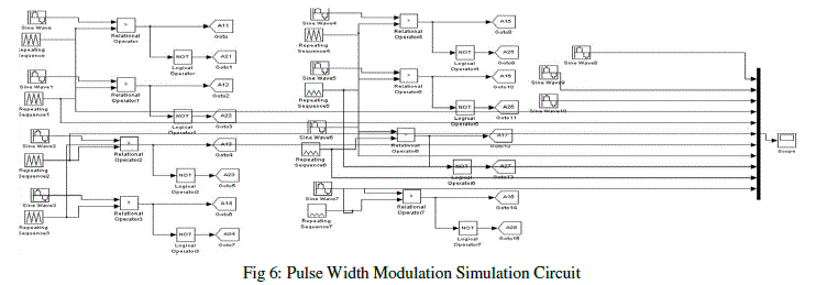
| Fig.6. shows the PWM circuit to generate the gating signals for the multilevel inverter switches. To control a three phase multilevel inverter with an output voltage of nine levels; two carriers are generated and compared at each time to a set of three sinusoidal reference waveforms. One carrier wave above the zero reference and one carrier wave below the reference. |
 |
SIMULATION RESULTS:
|
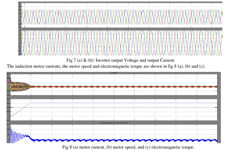
| The simulation results of voltage, current, motor speed and electromagnetic torque were presented. Fig 7 shows the waveform of sine-triangle intersection. Two carriers together with modulation signal have been used to obtain Multi Carrier PWM control. |
 |
| The inverter output voltage is shown in Fig 7(a) and the output current is shown in Fig 7(b). Here the output voltage contains nine level voltages because of nine level multi level inverter and the output current is continuous sinusoidal waveform. |
 |
| The FFT analysis for the motor drive system was also done as shown in Fig 9. |
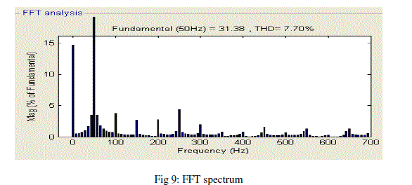 |
| It is seen that the percentage of harmonics in the multilevel inverter fed motor drive system is less compare to classical inverter system. |
CONCLUSION
|
| The modelling of nine level inverter fed induction motor drive was done and simulated using Simulink. The total harmonic distortion is very low compared to that of classical inverter and five level inverter. The simulation result shows that the harmonics have been reduced considerably. The nine level inverter fed induction motor system has been successfully simulated and the results of voltage waveforms, current waveforms, motor speed, electromagnetic torque and frequency spectrum for the output were obtained. The inverter system can be used for industries where the adjustable speed drives are required. |
References
|
- Jose, Steffen Sernet, Bin Wu, Jorge and SamirKouro, “Multilevel Voltage – Source - Converter Topologies for Industrial Medium - Voltage Drives,” IEEE Trans on Industrial Electronics, vol.54, no.6, Dec 2007.
- Dr.Rama Reddy and G.Pandian, “Implementation of Multilevel inverter fed Induction motor Drive,” Journal of IndustrialTechnology, vol 24, no. 1, April 2008.
- Nikolaus P. Schibli, T. Nguyen, and Alfred C. Rufer, “A Three-Phase Multilevel Converter for High - Power Induction Motors,”IEEE Trans on Power Electronics, vol.13, no.5, Sept 1998.
- N.Celanovic and D.Boroyevich, “ A Comprehensive study of neutral-pointvoltage balancing problem in three-level neutral –pointclamped voltage source PWM inverters,” IEEE Trans on Power Electronics, vol.15, no. 2, pp. 242 – 249, March 2000.
- K.Yamanaka and A.M.hava, “A novel neutral point potential stabilization technique using the information of output current polaritiesand voltage vector,” IEEE Trans on Ind. Appl, vol.38, no. 6, pp. 1572– 1580 Nov/Dec 2002.
- Fang ZhengPeng, “ A Generalized Multilevel Inverter Topology with Self Voltage Balancing,” IEEE Trans on Ind. Appl, vol. 37, no.2, pp 611-618 Mar/April 2001.
- J. Rodriguez, J.S. Lai, Fang Z. Peng, “Multilevel Inverters: A Survey of Topologies, Controls and Applications,” IEEE Trans onIndustrial Electronics, vol.49, no.4, pp 724-738 Aug 2002.
- L.M.Tolbert and T.G.Habetler, “Novel Multilevel Inverter Carrier Based PWM methods,” IEEE Trans on Ind. Appl, vol.35, pp. 1098-1107, Sept.1999.
|