The paper presents the implementation of Thyristor Controlled Series Compensator Flexible Alternating Current Transmission System Device, for optimizing the Available Transfer Capability. The goal of the optimization is to find the best location of a given number of FACTS devices for loss minimization.The successful application of a device in a power system requires considering not only the Technical Feasibility but also the economical feasibility. IEEE 30-Bus Test Power System has been considered for the study. The Technical Objective of the study is Reduction of Losses by implementing TCSC FACTS device, and the Economical Objective is determining the Cost-Benefit of applying TCSC.
Keywords |
| Thyristor Controlled Series Compensator, Flexible Alternating Current Transmission System, Technical
Objective, Economical Objective, Cost - Benefit. |
INTRODUCTION |
| The growth in demand for electric power, restructuring of Electric Power industry, diverse methods of Electric Power
Generation, Transmission and Distribution and the Competitive market demands[1] systematic approaches for effective and
efficient management of Electric Power System. The Objective of Managing Electric Power System is i) framed in view of
the present perspective and the future, with basis drawn from the past history of its performance, ii) the Objectives are
classified into two major categories to meet the growing demand of Electric power in terms of Quantity and Quality. The
first category of Objective is Technical Objective and the second category is Economic and Financial Objective. The
Technical objective is to provide Electric Power continuously at the rated voltage and frequency at all time to all customers.
To Optimize the Technical Objective several sub-optimal objectives are framed depending upon several factors such as the
type of loads to be served and the socio economic factors. Some of the sub-optimal objectives are enhancing the Available
Transfer Capability (ATC), increase in line flow on the transmission lines and reduction of losses. |
| According to the report of NERC (1995) [2], transfer capability refers to the ability of transmission systems to reliably
transfer power from one area to another over all transmission paths between those areas under given system conditions. The
mathematical definition of ATC given in the report of NERC (1996) [3] is „ . . . the Total Transfer Capability (TTC) less
the Transmission Reliability Margin (TRM), less the sum of existing transmission commitments and the Capacity Benefit
Margin (CBM)‟: |
| ATC = TTC − TRM − existing transmission commitments (including CBM). (1.0) |
| TTC refers to the maximum amount of electric power that can be transferred over transmission systems without violating
system security constraints. The accuracy of the ATC calculation is highly dependent on the accuracy of available network
data, load forecast, and the estimation of future energy transactions. |
| FACTS is defined by the IEEE as "a power electronic based system and other static equipment that provide control of one
or more AC transmission system parameters to enhance controllability and increase power transfer capability."[4] FACTS
Technology consists of electronic based equipment with real time operating control. Research studies are widely being
conducted to decide on the technical aspects of FACTS such as location, size and the number of FACTS devices to be
installed in a power system for its performance optimization. |
| The implementation of any system or device involves finance. System Planners have to consider a variety of options and
they have to take decisions based on technical and cost consideration. |
| The paper aims to conduct studies with the i) technical objective of determining the optimal location of the FACTS devices
for reduction of losses and enhancement of Available Transfer Capability and ii)the economic objective of determining the
cost of investment for the FACTS device. |
| The remainder of the paper is organized as follows: Section II Related Work, Section III Available Transfer Capability,
Section IV FACTS Devices, Section V Mathematical Modeling of TCSC FACTS Device, Section VI Proposed Approach,
Section VII Case Study, Section VIII Results and Discussion, Section IX Conclusions. |
RELATED WORK |
| Several studies have been conducted for fast, accurate determination of Available Transfer Capability and enhancement by
application of FACTS Devices. Placement of FACTS Devices is an important factor for optimizing the performance of the
Power System. For transmission networks, one of the major consequences of the non-discriminatory open-access
requirement is a substantial increase of power transfers, which demand adequate available transfer capability (ATC) to
ensure all transactions are economical. In this paper, report is presented on the study conducted for enhancement of ATC
with the objective of minimizing active power transmission losses and use of TCSC FACTS device. Researchers have
proposed the computation of ATC using AC power transfer distribution factors (ACPTDF) [5]-[7]. New methods of
evaluating ATC in a competitive environment are proposed in previous research [8], [9]. Manikandan et.al. [1] have
adopted Particle swarm optimization (PSO) algorithm to obtain the optimal settings of FACTS devices. The installation
cost is also calculated. The study had been carried out on IEEE 30 bus and IEEE 118 bus systems for the selected bilateral,
multilateral and area wise transactions and determined that there is considerable boost in ATC with FACTS Devices. Jigar
S.Sarda et. al. [10] have presented a novel method for optimal location of FACTS devices in a multi machine power system
using Genetic Algorithm(GA).Using the proposed method, the location of FACTS controllers, their type and rated values
were optimized simultaneously. The proposed algorithm has been applied to IEEE-30 bus system and results proved that
there is considerable decrease in losses and increase in power flow. |
AVAILABLE TRANSFER CAPABILITY (ATC) |
| The maximum power that can be transferred from one area to another area is called transfer capability[11]. In 1996, North
American Electric Reliability Council (NERC) established a framework for Available Transfer Capability (ATC) definition
and evaluation. According to the NERC definition, ATC is the transfer capability remaining between two points above and
beyond already committed uses (NERC, 1996). The ATC value between two points is given as: |
| ATC = TTC – TRM – CBM – ETC (1) |
| Where TTC is total transfer capability, TRM is transmission reliability margin, CBM is capacity benefit margin and ETC is
existing transmission commitment including customer services between the same two points. |
| According to the NERC definition in Equation 1, utilities would have to determine adequately their ATCs to ensure that
system reliability is maintained while serving a wide range of transmission transactions. ATC must be calculated, updated
and reported continuously to Load Servicing Entities(LSE) in normal and contingency situation. The ATC calculation must
cove all below principles: |
| 1. Provide the logical and reliable indication of transfer capability. |
| 2. Identification time-variant conditions, synchronous power transfers, and parallel flows. |
| 3. Considering the dependence on points of injection / extraction. |
| 4. Considering regional coordination. |
| 5. Covering the NERC and other organizational system reliability criteria and guides. |
| 6. Coordinate reasonable uncertainties in transmission system conditions and provide flexibility. |
| Operating studies commonly seek to determine limitations due to the following types of problems: |
| 1. Thermal overloads Limitation |
| 2. Voltage stability Limitation |
| 3. Voltage limitation |
| 4. Power generated Limitation |
| 5. Reactive power generated Limitation |
| 6. Load Power Limitation |
FACTS DEVICES |
| Flexible AC Transmission System (FACTS)[12][13] incorporates power electronic-based and other static Controllers to
enhance controllability and increase power transfer capability. The significance of power electronics and other static
Controllers is that they have high speed response and there is no limit to the number of operations. FACTS Controllers can
dynamically control line impedance, line voltage and active and reactive power flow. They can absorb or supply reactive
power and with storage they can supply and absorb active power as well. FACTS technology allows practically complete
utilisation of the capacity of transmission elements up to their limits and provides different kinds of devices which could
redirect the power in real-time. FACTS Devices are classified in three ways: |
| 1. Based on Technology as First Generation and Second Generation |
| 2. Based on the way of connecting to the ac power system as Seris and Shunt |
| 3.Basedd on the Parameter they control |
| These classifications are independent, existing for example, devices of a group of the first classification that can belong to
various groups of the second classification. |
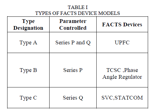
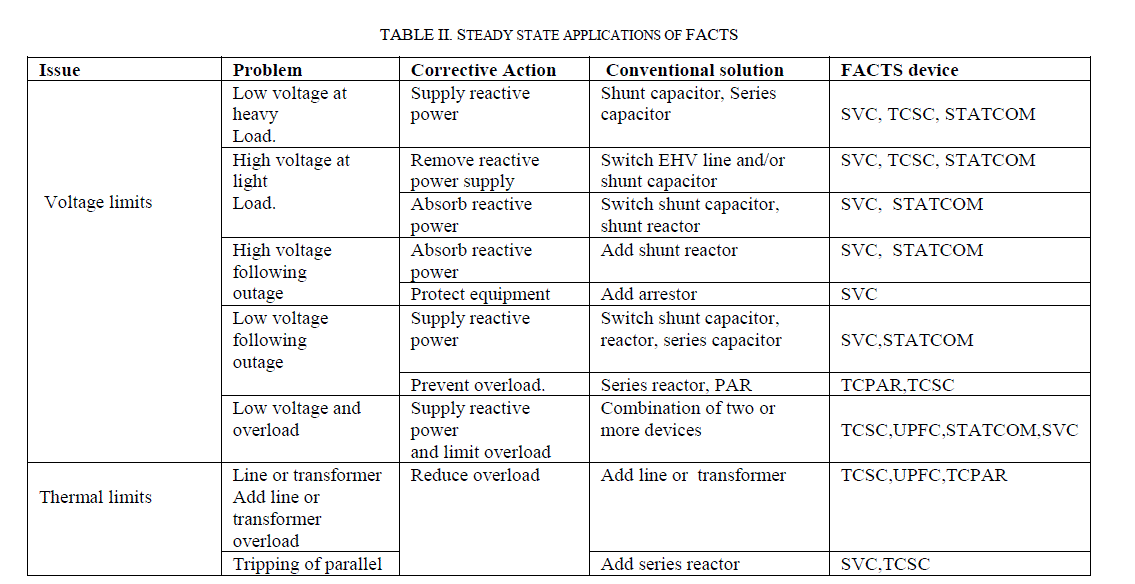
| Table I lists the several types of FACTS device models.. [14]. The application of the various FACTS devices as a solution
for the corrective action of the problems that arise in a Power System are furnished in Table II. |
 |
| SVC = Static Var Compensator TCSC = Thyristor Controlled Series Capacitor |
| STATCOM = Static Compensator UPFC = Unified Power Flow Controller |
| BENEFITS OF UTILIZING FACTS DEVICES |
| · Better utilization of existing transmission system assets |
| · Increased transmission system reliability and availability |
| · Increased dynamic and transient grid stability and reduction of loop flows |
| · Increased quality of supply for sensitive industries |
| · Environmental benefits |
 |
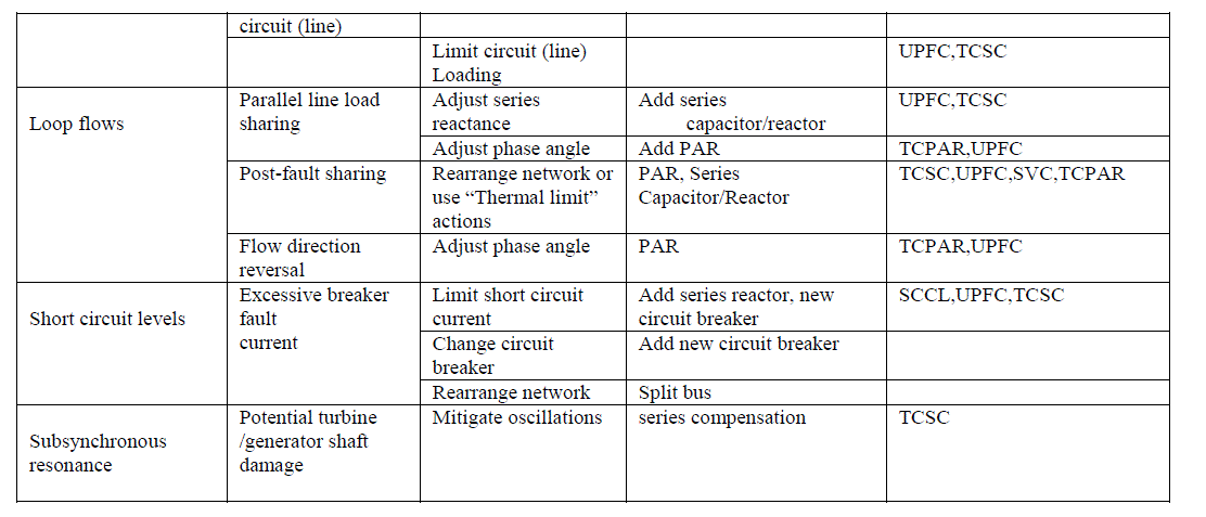 |
| SCCL = Super-Conducting Current Limiter |
| TCPAR = Thyristor Controlled Phase-Angle Regulator |
Mathematical Modeling of TCSC FACTS Device |
| TCSC controllers use thyristor-controlled reactor (TCR) in parallel with capacitor segments of series capacitor bank.
TCSC, the first generation of FACTS, can control the line impedance through the introduction of a thyristor controlled
capacitor in series with the transmission line. A TCSC is a series controlled capacitive reactance that can provide
continuous control of power on the ac line over a wide range. The functioning of TCSC can be comprehended by analyzing
the behavior of a variable inductor connected in series with a fixed capacitor. TCSC is an effective and economical means
of solving problems of transient stability, dynamic stability, steady state stability and voltage stability in long transmission
lines. |
| For static applications, FACTS devices can be modeled by Power Injection Model (PIM) [15]. The injection model
describes the FACTS as a device that injects a certain amount of active and reactive power to a node, so that the FACTS
device is represented as PQ elements. The PIM doesn‟t destroy the symmetrical Characteristic of the admittance matrix and
allows efficient and convenient integration of FACTS devices in to existing power system analytical tools. This is the main
advantage of PIM. |
| During the steady state condition, the TCSC can act as capacitive or inductive mode, respectively to decrease or increase
the impedance of branch. The TCSC is modeled with variable series reactance. Its value is function[16] of the reactance of
line, XL , where the device is located. The upper and lower limit of TCSC reactance is given in equation (2). |
| 0.8 XL ≤ X ≤0.2 XL (2) |
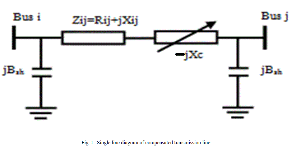 |
| In Fig ., it shows the model of transmission line with TCSC connected between buses i and j. The transmission line is
represented by its lumped π equivalent parameters connected between the two buses and TCSC as a variable reactance. |
PROPOSED APPROACH |
| The proposed methodology to study the enhancement of Available Transfer Capability using FACTS Devices and study
the economics of FACTS has two stages: |
| Stage 1: Technical Objective Stage |
| Stage 2: Economic Analysis Stage |
Technical Objective Stage |
| The Technical Objective is determining the Optimal Location of FACTS device for real power loss reduction and
thereby enhance the Available Transfer Capability of the Power System. The Objective for placement of the FACTS device
is reduction of real power losses[17][18]. The criteria for placement of FACTS device is the lines with maximum Active
Power(MW) loss[19]. Mathematically stating : |
| Objective function |
| Minimize ΣPLi (3) |
| Where PLi = Power Loss on Line i: i = 1…n And ‘n’ is the no. of lines |
| While solving the optimization problem, power balance equations are taken as equality constraints. The power balance
equations are given by, |
| ΣPG = ΣPD + ΣPLi .. (4) |
| Where ΣPG = Total power generation |
| ΣPD = Total power demand |
| ΣPLi = Total power loss |
| The power flow equations are: |
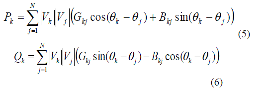 |
| Where |
| Pk = Real power injected at bus k |
| Qk = Reactive power injected at bus k |
| Ɵk , Ɵj = Phase angles at buses k and j respectively; |
| Vk , Vj = Voltage magnitudes at bus k and j respectively; |
| Gkj, Bkj = Elements of Y-bus matrix |
| Economic Objective Stage |
| The Objective of Economic Analysis is to determine the cost of TCSC FACTS devices. The range of cost of major FACTS
devices is presented in Siemens AG Database [20]. Based on this, a polynomial cost function of FACTS devices is derived
and used for FACTS allocation study as used in [21][22]. The cost function of TCSC is given by equation (7). |
 |
| where CTCSC is the cost of TCSC in US$ / KVar and S is the operating range of TCSC in MVAr. and
Annual capital cost of FACTS in US$/year can be found as: |
 |
 |
| and Q2 and Q1 are the reactive power flow in the line after and before installing FACTS device in MVAR respectively. |
| The cost of TCSC for different operating ranges‟ of TCSC has been computed as per equation 7.The Range selected is from
5MVAr to 750MVAr. The range has been categorized into two groups: |
| Low Operating Range : 5MVAr to 95MVAr |
| High Operating Range : 100MVAr to 750MVAr |
| The graphs of „TCSC Operating Range Vs Cost of TCSC in US$/KVAr for the Low Operating Range is Figure II and for
the High Operating range is Figure III. It can be seen from the graph that the Optimum Operating range of TCSC is
between 225MVAr – 275MVAr. |
| TCSC Operating Range Vs Cost in US$/KVAr |
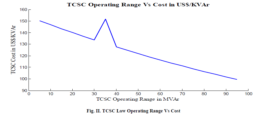 |
| In Fig. II, it shows the graph of the TCSC Operating Range Vs Cost in US$/KVAR. This graph is for low operating range
upto 95MVAr. |
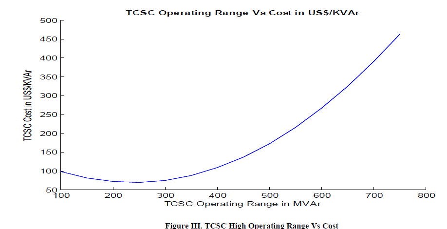 |
| In Fig. III, it shows the graph of the TCSC Operating Range Vs Cost in US$/KVAR. This graph is for high operating range from above 95MVAr to
750MVAr.. |
CASE STUDY |
| VII.1 Stage 1: Technical Analysis |
| The proposed approach is applied to the IEEE 30BusTest System. The steps of the study are: |
| 1. Prepare the One-Line Diagram of the System for study. |
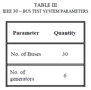
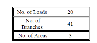
| The One-Line Diagram of the 30 Bus System is shown in Figure IV. The System Parameters are furnished in Table III. |
| 2. Run the Base Case Optimal Power Flow(OPF) Algorithm to obtain the Base Case Results. |
| 3. From the Base Case Results determine the Branches with maximum Real Power Losses. In this Case Study the five
branches identified are between buses 1-3,2-4,2-6,24-25 and 25-27 which are having maximum MW loss. |
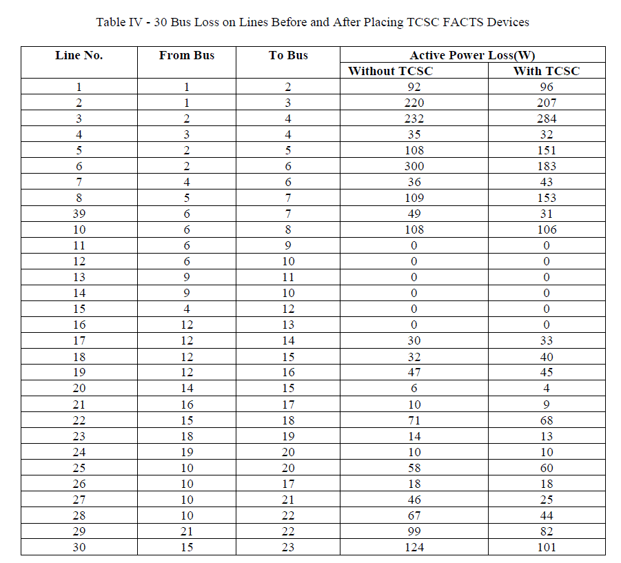
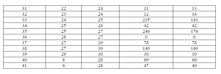
| 4. TCSC is placed in these lines. OPF is executed after placement of TCSC. Table IV gives the losses on the lines before
and after placing TCSC FACTS devices in the selected lines of step 3. |
| 5. The results obtained without placing of TCSC and after placing of TCSC are compared and analyzed. The analysis of the
results reveals a reduction of real power loss of 9.4% with TCSC. |
| Figure V depicts the Losses in all the lines of 30-Bus Test System Before and After placing TCSC. |
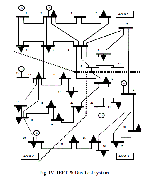 |
| In Fig. IV, it shows the One Line Diagram of the IEEE 30 Bus Test System. The One Line diagram is the graphical representation of the electric power
system which shows the interconnection of the buses with the transmission lines called branches, and the generators and loads at the various buses. |
 |
 |
| VII.2 Stage 2: Economic Analysis Stage of Case Study |
| In the Technical Analysis Stage the size, number and the Location of TCSC has been determined. In the second stage,
which is the Economic Analysis Stage the cost of TCSC is calculated from equation 6, 7 and 8. The Reactive Power on the
lines where TCSC is placed is determined for the system with TCSC(Q1) and without TCSC(Q2). The valus of S is
computed and applied in equation 6 to determine the cost of TCSC. The Annual Cost of TCSC is computed by equation 7. |
| The details of the Cost computations are Tabled in Table V. |
 |
 |
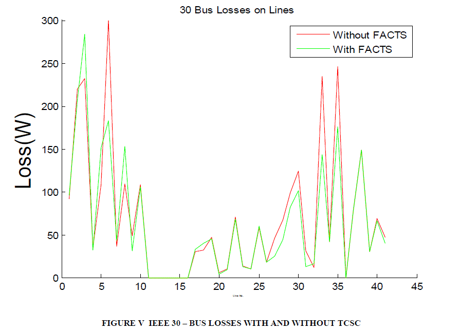 |
| In the Fig. V, it shows the graph of Losses on the branches of IEEE 30 – Bus Electric Power System in Watts, without
FACTS Device and with FACTS Device. There are 41 branches in the System. A branch is a transmission line
interconnecting two buses. The X-Axis indicates the branch number and the Y-Axis the corresponding Losss in Watts on
the branch. The graph in Red is the graph without FACTS Device and the graph in Green with FACTS Device. It is
observed from the graph that there is a decrease in Losses with FACTS Device. |
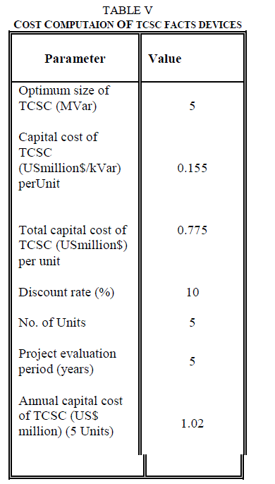 |
| The total Cost of the five TCSC placed has been determined to be 0.77million dollars / MVAr. |
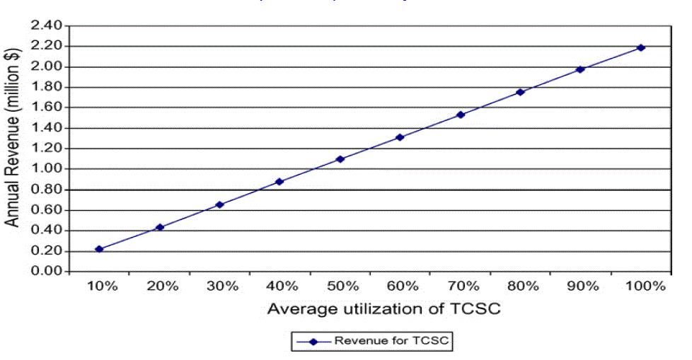 |
| Figure VI. Annual revenue at different TCSC utilization factor |
| In Figure VI, it shows the change in annual revenue generated for TCSC investment recovery, when average utilization of
TCSC is changed. From Figure VI it can be clearly determined that for the 30 Bus system under study, the investment on
five TCSC units can be realized in 5 years with about 45% utilization. The same amount considering 10years of evaluation
period can be realized with even 28% utilization. |
Results and Discussion |
| 30 Bus Test system was considered for the study. The Technical Objective results obtained show the reduction of losses
with TCSC. The economic analysis has shown the investment cost of TCSC and its realization rate. |
CONCLUSIONS |
| FACTS devices have proved an effective method for Loss reduction. The effectiveness of TCSC is demonstrated on 30 –
Bus IEEE Power Systems. The main conclusions of the paper are: i) The time of convergence is less. ii) The placement of
Facts devices mitigates real power loss. iii) The simple and direct method of placing TCSC in the lines having maximum
power loss has shown effective results in loss reductio. iv) TCSC Facts devices have proven Technical and Economical
benefits. |
References |
- B.V. Manikandan, S. Charles Raja, and P. Venkatesh, “Available Transfer Capability Enhancement with FACTS Devices in the Deregulated Electricity Market”, Journal of Electrical Engineering & Technology Vol. 6, No. 1, pp. 14~24, 2011 DOI: 10.5370/JEET.2011.6.1.014.
- A Reference Document for Calculating and Reporting the Electric Power Transfer Capability of Interconnected Power Systems, NERC, 1995.
- North American Electric Reliability Council (1996) Available Transfer Capability Definitions and Determination. Princeton, NJ: NERC.
- Proposed terms and definitions for flexible AC transmission system(FACTS), IEEE Transactions on Power Delivery, Volume 12, Issue 4, October 1997, pp. 1848–1853. doi: 10.1109/61.634216.
- J.Weber, “Efficient Available Transfer Capability Analysis using Linear methods”, PSERC internetseminar, UL, USA, Nov 7, 2000.
- A.Kumar and S.C. Srivatsava, “AC Power Distribution Factors for allocating Power transactions in a deregulated environment”, IEEE PowerEngineering Review, pp. 42-43, 2002.
- A. Kumar, S.C. Srivatsava and S.N.Singh, “ATC determination in a competitive electricity market using AC Distribution Factors”, Electrical Powercomponents and Systems, Vol. 32, No. 9, pp. 927-939, 2004.
- A.M. Leite da silva, J.G.C. Costa, L.A.F. Manso and G.J. Anders, “Evaluation of transfer capabilities of transmission systems in competitiveenvironments”, Electrical Power and Energy systems, Vol. 26, No. 4, pp. 257-263, 2004.
- M.M Othman, A. Mohamed and A. Hussain, “Fast Evaluation of Available Transfer Capability usingCubic-spline interpolation technique”, Electric Power systems research, Vol. 73, No. 3, pp. 335-342, 2005.
- JigarS.Sarda, VibhaN.Parmar, DhavalG.Patel, LalitK.Patel, “Genetic Algorithm Approach for Optimal location of FACTS devices to improvesystemloadability,and minimization of losses”, International Journal of Advanced Research in Electrical, Electronics and Instrumentation Engineering,ISSN 2278 – 8875, Vol. 1, Issue 3, September 2012
- MojganHojabri and HashimHizam, “Available Transfer Capability Calculation “, Universiti Putra Malaysia, Applications of MATLAB in Science\and Engineering , www.intechopen.com.
- Narain G. Hingorani, Life Fellow, IEEE,”FACTS Technology – State of the Art, Current Challenges and the Future Prospects”, 1-4244-1298-6/07/$25.00 ©2007 IEEE.
- N. G. Hingorani and L. Gyugyi, “Understanding FACTS Concepts and Technology of Flexible AC Transmission Systems, IEEE Press”.
- K.Vijayakumar, SRM University, Kattankulathur, Chennai, “Optimal Location of FACTS Devices for Congestion Management in DeregulatedPower Systems”, International Journal of Computer Applications (0975 – 8887), Volume 16– No.6, February 2011.
- Nadaraj10ah Mithulananthan ,NareshAcharya, “A proposal for investment recovery of FACTS devices in deregulated electricity markets”, ElectricPower Systems Research 77 (2007) 695–703.
- AbouzarSamimi, PeymanNaderi, “ A New Method for Optimal Placement of TCSC Based on Sensitivity Analysis for Congestion Management”,Scientific Research, Smart Grid and Renewable Energy, 2012, 3, 10-16, http://dx.doi.org/10.4236/sgre.2012.31002 Published Online February 2012(http://www.SciRP.org/journal/sgre)
- J.NamrathaManohar, J. Amarnath, P.C. Rao, “Optimization of Loss Minimization Using FACTS in Deregulated Power Systems”, Innovative SystemsDesign and Engineering www.iiste.org, ISSN 2222-1727 (Paper) ISSN 2222-2871 (Online), Vol 3, No 3, 2012.
- N.M. Tabatabaei, Gh. Aghajani, N.S. Boushehri, S. Shoarinejad ,” Optimal Location Of FACTS Devices Using Adaptive Particle SwarmOptimization Mixed With Simulated Annealing”, ISSN 2077-3528 IJTPE Journal www.iotpe.com ijtpe@iotpe.com June 2011 Issue 7 Volume 3 Number2 Pages 60-70
- JigarS.Sarda, VibhaN.Parmar,, DhavalG.Patel, , LalitK.Patel, “Genetic Algorithm Approach for Optimal location of FACTS devices to improvesystemloadability and minimization of losses”, International Journal of Advanced Research in Electrical, Electronics and Instrumentation Engineering,Vol. 1, Issue 3, September 2012, ISSN 2278 – 8875, http://www.ijareeie.com/upload/september/2_Genetic%20Algorithm%20Approach%20for.pdf
- K. Habur, D. O‟Leans, “FACTS-flexible alternating current transmission systems: for cost effective and reliable transmission of electrical energy”,available atwww.worldbank.org/html/fpd/em/transmission/facts siemens.pdf.
- L.J. Cai, I. Erlich, G. Stamtsis, “Optimal choice and allocation of FACTS devices in deregulated electricity market using genetic algorithm”, in: IEEEPES Power System Conference and Exposition, New York, USA, October 10–13, 2004.
- A. B.Bhattacharyya, B. S.K.Goswami, “OPTIMAL Placement of FACTS Devices by Genetic Algorithm for the Increased Load Ability of a PowerSystem”, World Academy of Science, Engineering and Technology 75 2011.
|