This paper presents the d various issues related to the power quality. The interest in power quality is explained in the context of a number of wider developments in power engineering such as deregulation of the electricity industry, increased customer-demand. Two power quality disturbances are discussed in detail: voltage dips and harmonic distortion. Shunt, hybrid and advanced series active power filters are described showing their compensation characteristics and principles of operation. The performance of the advanced series active power filters carried out in MATLAB/SIMULINK environment.
Keywords |
| Power quality, voltage sag voltage Swell, series active power filters, Active filters. |
INTRODUCTION |
| Power quality phenomena include all possible situations in which the waveform of the supply voltage (voltage quality)
or load current (current quality) deviate from the sinusoidal waveform at rated frequency with amplitude corresponding
to the rated rms value for all three phases of a three-phase system [1].Firstly, the voltage dips and interruptions, mostly
caused by faults in the power system. These disturbances may cause tripping of “sensitive” electronic equipment with
disastrous consequences in industrial plants where tripping of critical equipment can bear the stoppage of the whole
production with high costs associated. Secondly, due to low quality of the current drawn by the load[8]. In this case, it
is the load that disturbs the source [2].Both harmonics and unbalanced currents ultimately cause distortion [3]. The
compensating devices are used for active filtering; load balancing, power factor correction and voltage regulation [4]. |
| This paper presents that any disturbances caused in the supply voltage will result in the malfunctioning of the electrical
equipment, also results in lower efficiency and also complete shutdown of the equipments[8]. Series Active power
filters have been developed to overcome these problems. |
POWER QUALITY |
| The Power Quality issue is defined as “any occurrence manifested in voltage, current, or frequency deviations that
results in damage, upset, failure, or malfunctioning of end-use equipment”. The Power Quality (PQ) problem can be
detected from one of the following several symptoms depending on the type of issue involved such as Lamp
flicker, Frequent blackouts ,Sensitive-equipment frequent dropouts, Communications interference and Overheated
elements and equipment[2]. Conventionally, passive filters have been used to eliminate harmonic problems. This filter
consists of common devices such as inductance and capacitance[10]. |
| There are two approaches to the mitigation of power quality problems. The first approach is called load conditioning,
which ensures that the equipment is made less sensitive to power disturbances, allowing the operation even under
significant voltage distortion [5]. The other solution is to install line-conditioning systems that suppress or counteract
the power system disturbances. |
MODELING OF SERIES ACTIVE POWER FILTER |
| The series active filter injects a voltage component in series with the supply voltage and therefore can be regarded as a
controlled voltage source, compensating voltage sags and swells on the load side[4]. |
 |
| The main advantage of this scheme is that the rated power of the series active filter is a small fraction of the load KVA
rating, typically 5%. However, the apparent power rating of the series active power filter may increase in case of
voltage compensation [6]. The main function of a series active power filter is the protection of sensitive loads from
supply voltage sags, swells and harmonics. |
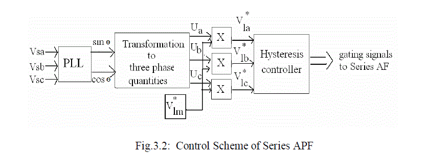
| 3.1 CONTROL SCHEME OF SERIES FILTER |
| A simple algorithm is developed to control the series and shunt filters [8]. The series filter is controlled such that it
injects voltages (Vca,Vcb,Vcc ) which cancel out the distortions and/or unbalance present in the supply voltages
(Vsa,Vsb,Vsc) thus making the voltages at the PCC (Vla,Vlb,Vlc) perfectly balanced and sinusoidal with the desired
amplitude. The control strategy for the series AF is shown in Fig. 3.2. |
 |
| 3.2 REFERENCE VOLTAGE GENERATION & HVC |
| Since the supply voltage is unbalanced and or distorted, a phase locked loop (PLL) is used to achieve synchronization
with the supply. This PLL converts the distorted input voltage into pure three phase sinusoidal supply of RMS value of
each phase equal to that of the fundamental (1 p.u).The in-phase sine and cosine outputs from the PLL are used to
compute the supply in phase, 1200 displaced three unit vectors (ua,ub,uc ) using eqn.(3.1) as |
 |
| The computed three in-phase unit vectors are then multiplied with the desired peak value of the PCC phase voltage
(V*
lm), which becomes the three-phase reference PCC voltages as |
 |
| The hysteresis controller generates the switching signals such that the voltage at the PCC becomes the desired
sinusoidal reference voltage[10]. Therefore, the injected voltage across the series transformer through the ripple filter
cancels out the harmonics and unbalance present in the supply voltage. |
ADVANCED SERIES ACTIVE POWER FILTER |
| The advanced series active power filter is used to compensate the source side disturbances such as voltage sags, swells
and also harmonic distortions [6]. In this configuration, the filter is connected in series with the line being
compensated. Therefore the configurations are often referred to as an advanced series active filter. |
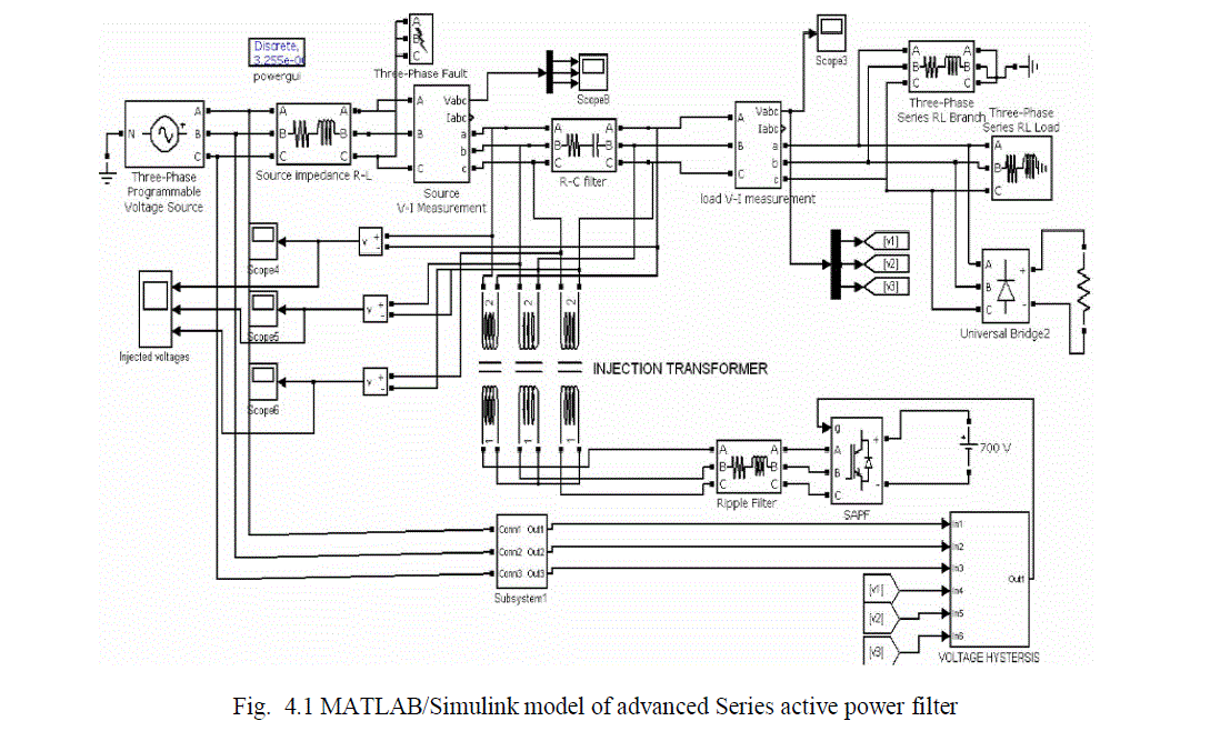 |
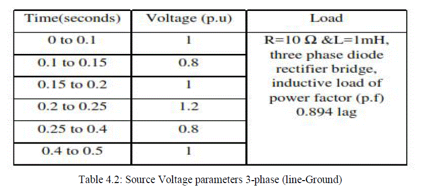
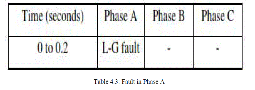
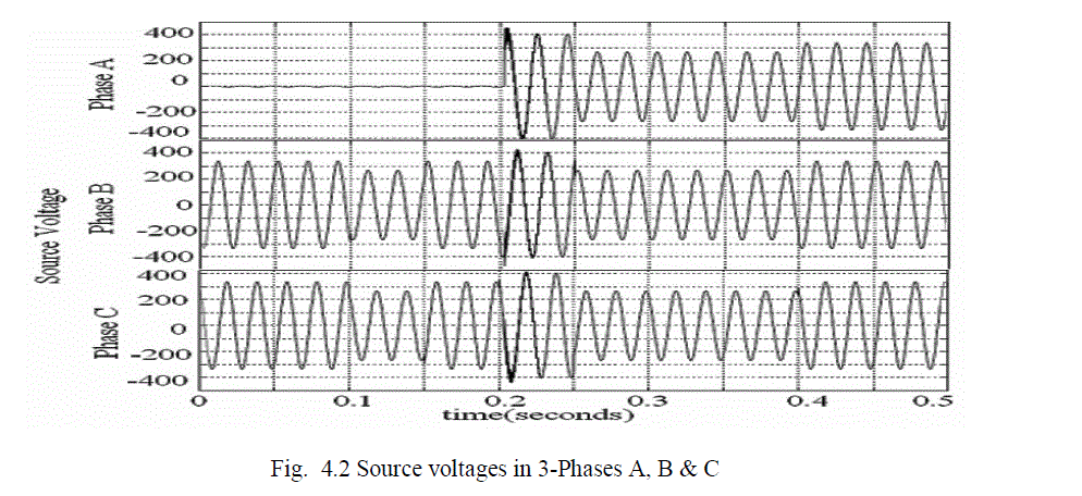
| Fig. 4.1 shows the source voltage in which rated 1 p.u voltage is created from 0 to 0.1 seconds, 0.8 p.u sag from 0.1 to
0.15 seconds,1 p.u voltage from 0.15 to 0.2 seconds, 1.2 p.u swell from 0.2 to 0.25 seconds , 0.8 p.u sag from 0.25 to
0.4 seconds , 1 p.u voltage from 0.4 to 0.5 seconds . A L-G fault occurs in phase A from 0 to 0.2 seconds .The load is
R=10 Ω and L=1mH, a three phase diode rectifier bridge, an inductive load of power factor (p.f) 0.894 lag (active
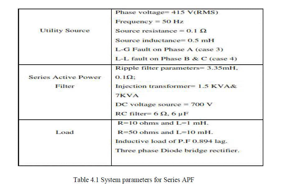
power =1000W and reactive power = 500W). The data for the Advanced Series active power filter is shown in Table
4.1., the individual three phase voltage is shown in table. 4.2 and fault in phase A shown in table 4.3. |
 |
 |
 |
| The Source voltages in 3-Phases A, B & C are shown as follows. |
 |
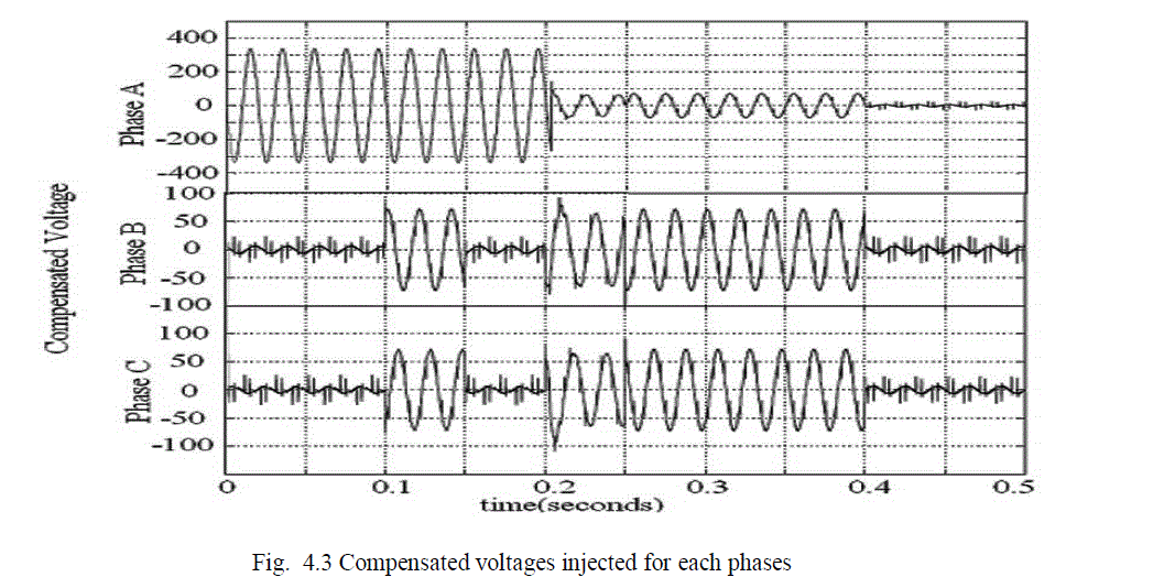
| Fig. 4.3 shows the compensated voltage injected by each phases to cancel the source side disturbances present in the
system. The approach was based on the principle of injecting voltage in series with the line through the injection
transformer to cancel the source side voltage disturbances and thus it made the load side voltage sinusoidal. finally the
source side voltage disturbances is cancelled and got ripples free source voltage |
 |
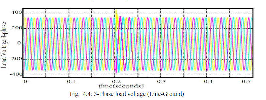
| Due to the injection of the above voltages through the injection transformer in series with the line the load voltage is
sinusoidal as shown in the Fig. 4.4 |
 |
| Active filters able to compensate for harmonics without fundamental frequency reactive power concerns. This means
that the rating of the active power can be less than a conquerable passive filter for the same nonlinear load and the
active filter will not introduce system resonances that can move a harmonic problem from one frequency to another and
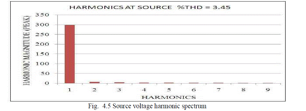
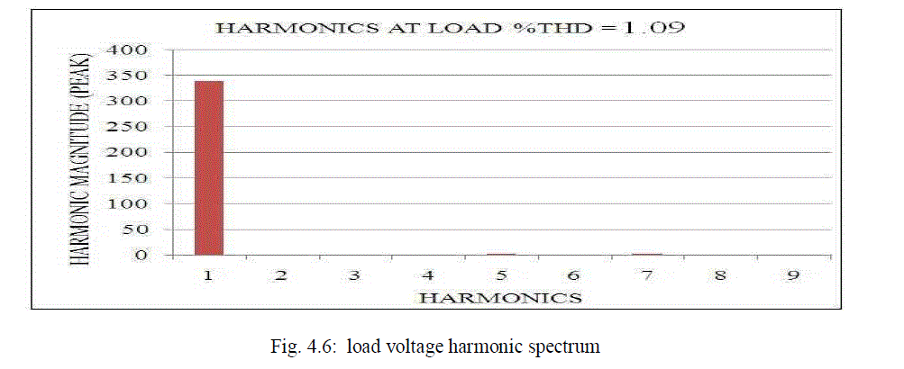
got ripple free line voltage. The Total harmonic distortion of source voltage is 3.52% and load voltage is 1.09 % as
shown in fig 4.5 and fig 4.6 respectively. |
 |
 |
| The information regarding the harmonic spectrum, generated by a nonlinear load which is supplied to the referencecurrent/
voltage estimator together with information about other system variables. The reference signal from the current estimator, as well as other signals, drives the overall system controller. The SAPF is simulated with interruptions in the
form of Sag, Swell, LG fault in the input side on phase A & the performance of SAPF is analyzed by taking the FFT
analysis of the Source and load Voltages. Finally the harmonic magnitudes are suppressed. |
CONCLUSION & FUTURE SCOPE |
| Hysteresis controller based Series active power filter is implemented for harmonic and voltage distortion compensation
of the non-linear load. The Simulation is even extended for abnormal faults occurring on the power system like L-G &
L-L faults. The simulation results of series active power filter has shown the ability to compensate voltage sag, swell
and harmonics present at input source side. The THD of the load voltage is below 5%, the harmonics limit imposed.
The performance of the above mentioned Hysteresis controller based Series active filter can be improved by fuzzy logic
controller. |
References |
- Bhim Singh and venkateswarlu.P, âÃâ¬ÃÅA Simplified Control Algorithm for ThreePhase, Four-Wire Unified Power Quality ConditionerâÃâ¬Ã Journal of Power Electronics, Vol.10, No.1, January 2010 pp.91-96.
- B.Singh,K.Al-Haddad,and A.Chandra, âÃâ¬ÃÅA review of active power filters for power quality improvement,âÃâ¬Ã IEEE Trans.Ind.Electron.,vol.45,no.5,pp.960971,Oct 1999.
- V.Khadkikar,A.Chandra,A.O.Barry,and T.D.Nguyen, âÃâ¬ÃÅApplication of UPQC to protect a sensitive load on a polluted distribution network,âÃâ¬Ã in Proc.IEEE PES General Meeting,Montreal,QC,Canada,2006,6pp.
- V.Khadkikar, A.Chandra, A.O.Barry, and T.D.Nguyen, âÃâ¬ÃÅConceptual analysis of unified power quality conditioner (UPQC),âÃâ¬Ã in proc.IEEE ISIE, 2006, pp.10881093.
- Vinod Khadkikar and Ambrish Chandra, âÃâ¬ÃÅA Novel Structure for Three-Phase Four-Wire Distribution System Utilizing Unified Power Quality Conditioner (UPQC)âÃâ¬Ã IEEE Transactions on Industry Appl., Vol. 45, No. 5, September/October 2009.
- Yash Pal, A. Swarup, and Bhim Singh, âÃâ¬ÃÅ A Comparison of Three Topologies of Three-Phase Four-Wire UPQC for Power Quality ImprovementâÃâ¬Ã 16th National Power systems conference, 15th-17th December, 2010 pp.227-232.
- S. Chakraborty and F. A. Farret, âÃâ¬ÃÅA Single Phase High Frequency AC Microgrid with an Unified Power Quality Conditioner,âÃâ¬Ã Proceedings on IEEE 2003, pp.952-967.
- Sandeep G J S M, Sk. Rasoolahemmed, âÃâ¬ÃÅImportance of Active Filters for Improvement of Power Quality,âÃâ¬Ã International Journal of Engineering Trends and Technology (IJETT) - Volume4Issue4- April 2013.
- P.Chaithanyakumar, T.Varaprasad âÃâ¬ÃÅDesign of Unified Power Quality Conditioner (UPQC) to Improve the Power Quality Problems by Using P-Q Theory,âÃâ¬Ã International Journal of Engineering Research and Applications (IJERA) Vol. 2, Issue 3, May-Jun 2012, pp.1088-1094.
- Active power filter with automatic control circuit for neutral current harmonic minimization technique by mohd izhar bin a bakar.
|