The device used to phase out voltage sags and a swell in the distribution lines is the Dynamic Voltage Restorer (DVR). The DVR can restore the load voltage within few milliseconds by injecting series voltage which is actually missing voltage in to system through series connected booster transformer, when it is subjected to voltage sags. Generally DVR can be connected to grid through inverter topologies such as Voltage Source Inverter (VSI) or Current Source Inverter (CSI). Tradition inverters (VSI /CSI) suffers from problem of limited output voltage(below dc link voltage), limitation on switching of upper and lower switches simultaneously and filter is needed to give sinusoidal output. All these problems get eliminated if embedded EZ-source inverter is used. This paper presents control strategy for DVR based on EZ source inverter. It has been observed that switching losses and harmonics are reduced drastically.
Keywords |
| DVR, Current Source Inverter, EZ source inverter, Power Quality, Voltage Source Inverter, Voltage
sag. |
INTRODUCTION |
| The term power quality has become one of the most common expressions in the power industry during the last few
years due to extensive losses in power industry in terms of energy and money. Voltage sag and swell have been one of
the most important power quality problems because of which there is malfunctioning of end user’s equipment which in
turn causes interruption to the production [1]. Out of which voltage sags are more common as compared to voltage
swell. Dynamic voltage restorer is best solution to mitigate problem related with voltage sag and swell. DVR gives
good output voltage with low harmonic levels whenever it is incorporated with VSI topology. [2] But there are certain
demerits which are associated with conventional VSI is that ac output voltage is limited which cannot be exceeded ac
input voltage which makes this topology as buck type output characteristic and therefore the output voltage range and
further required voltage injection capability is limited. In addition to this, problem of shoot through or cross conduction
may destroy whole device and EMI causes mis-gating which again leads to shoot through problem and kills reliability.
We can prefer CSI also but again the demerits of traditional CSI includes same problem as given in VSI. Hence to
defeat the above problems of the traditional VSI and current source inverter (CSI), an impedance source inverter (Z
source inverter) is presented that can be use for implementing dc-to ac, ac-to-dc, ac-to-ac, and dc-to-dc power
conversions and applications. Z-Source inverter is a single-stage converter. It also performs both buck-boost energy
conversions utilizing the LC impedance network. It employs a unique impedance network to couple either the converter
main circuit to power source and load or another converter. This feature cannot be observed in the traditional voltage
and current-source converters where a capacitor and inductor are utilized, respectively [3]. |
LITERATURE SURVEY |
| Dugan R. C. [1] in his book describes a consistent terminology that can be used to describe power quality variations.
John Godsk Neilsen [2] in his thesis first gives an introduction to relevant power quality issues for a DVR and power
electronic controllers for voltage dip mitigation. Thereafter the operation and the elements in a DVR are described. The
basics of Z source inverter along with its advantages as compared to CSI and VSI is explained in paper published by
Fang Zheng Peng [3]. Rosli Omar, et al. [4] describes the problem of voltage sags and swells and its severe impact on
non linear loads or sensitive loads. The proposed control scheme of dq0 algorithm is simple to design. Basic concept of Embedded Z source inverter along with its shoot and non shoot through condition is explained by the paper i.e.
Embedded EZ-Source Inverters published by Poh Chiang Loh, Feng Gao [5]. N.Gurusakthi, R.Sivaprasad [6] and K
Ravi Chandrudu [7] gives application of E-Z source inverter and its performance attributes using induction motor drive.
Deokar S.A. [8] implemented with feed forward pre-sag/swell voltage control method to regulate the output voltage of
pulse width modulated (PWM) voltage source converter (VSC). The proposed controller maintains a constant load
voltage under the multiple balanced/unbalanced dynamic PQ disturbances. Nielsen, J.G. [9] explained the design and a
new control method of a DVR. The DVR is also tested at medium voltage level (10 kV) and methods to initiate voltage
dips are described and implemented. Different test results at 10 kV level show that the DVR keep the voltage to a
sensitive load fixed in the case of voltage dips. SNV Ganesh [10] presents different control strategies for DVR i.e.
Park’s transformation. |
THEROTICAL CONCEPT |
| A. Dynamic Voltage Restorer: |
| A Dynamic Voltage Restorer (DVR) is a type of switching converter which is basically DC-to-AC solid-state switching
converter. It is used to maintain distribution side voltage where sensitive equipments are connected. Basically it injects
three single phase AC output voltages. This is in series with the distribution feeder. The important condition is that this
voltage should be in synchronisms with the voltages of the distribution system [4]. DVR can restore the voltage quality
by injecting required amount of voltages which is also called as missing voltage. This injected voltage is having
controllable magnitude, phase angle, and frequency into the distribution feeder on instantaneous real time basis via a
series-injection transformer. Following fig.1 shows schematic diagram of DVR. |
 |
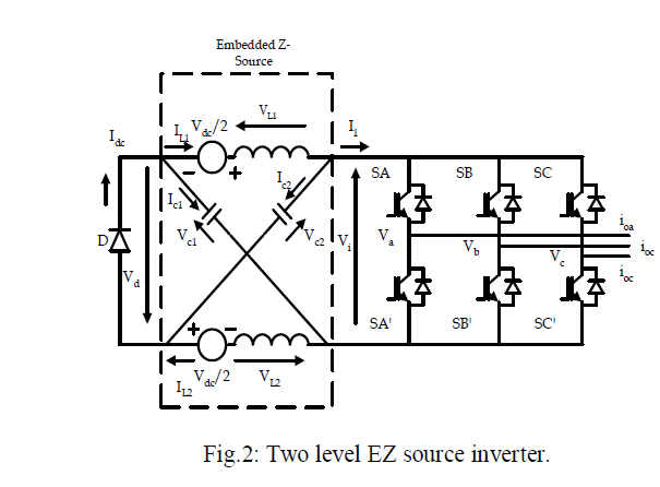
| B. EZ source inverter: |
| As compared to any traditional VSI and CSI, there is one additional switching state is present in Z and EZ source
inverter viz. shoot through or cross conduction condition i.e. when the d.c. supply in inverter gets shorted through
power devices of the same link. Hence we can prefer Z source inverter. Instead of using an external LC filter in case of
Z source inverter, there is an alternative family of embedded Z-source (referred to as EZ-source in short, where “E” is
included to represent “embedded”) inverters, which adopts the concept of embedding the input DC sources within the
LC impedance network, using its existing inductive elements for current filtering in voltage-type EZ source inverters,
and its capacitive elements for voltage filtering in current-type EZ-source inverters [5]. The proposed 2 level EZ–
source is as shown in Fig.2. |
 |
| Shoot-Through condition: |
| Fig. 3 shows shoot through condition in which diode D is in blocking state. Equations are as follows: [6] |
 |
 |
| Non shoot-Through condition: |
| In case of non shoot through active or null state, the redrawn equivalent circuit is shown in Fig.4 with diode D
conducting and the inverter bridge and external (usually inductive) load replaced by a current source, whose value is
nonzero for active state and zero for null state. Using this equivalent circuit, the second set of state equations is derived
as follows. [7] |
 |
 |
 |
 |
CASE STUDIES BASED ON SIMULATION |
| A. Distribution line model without DVR when fault occurs on load side (voltage sag condition): |
| Following fig.5 shows distribution line model without DVR when fault occurs on load side. Here fault is created on
load side. In the fault, transition time given is 0.15 to 0.2. Breaker resistances is 0.66 which gives 40% of voltage
sag and consider that there is switching in all three phases. During transition time i.e. during 0.15 to 0.2 time period,
fault occurs. Hence there will be drop in load voltage value and in supply voltage. |
 |
| Following fig.6 shows voltage sag condition i.e. reduction in load side voltage due to fault and hence there is also
reduction in supply voltage. |
 |
| B. Case-I) MATLAB simulation of DVR based on EZ source inverter when fault near load side: |
| A DVR is connected to the system through a series booster transformer with a transformation ratio equal to 1:1. The
DVR is based on three phase voltage EZ source inverter with LC output filter to remove high frequency voltage
components. An R-L load is considered. In this circuit the DVR is connected in between supply (PCC) and load. The
DVR is connected to the system through injecting transformer. After supply block, three phase VI measurement block
is connected to measure voltages. A feed forward connection is given through this VI measurement block to the voltage
regulator block. A voltage reference is given to this voltage regulator block. The feed forward measurement of supply
voltage value is compared with a reference value and the error signal is given to the PWM generator block. PWM
output is connected to IGBT of EZ source inverter block where the firing pulses of IGBTs are controlled by PWM
technique. The inverter block gets a dc source through dc voltage source block connected to the inverter. Inverter
output is connected to injecting transformer through LC filter. LC filter block is used to filter out harmonics in inverted
waveform. Following fig. 7 shows MATLAB simulation of DVR based on EZ source inverter when fault is created
near load side. |
 |
| Here fault is created on load side. In the fault, transition time given is 0.15 to 0.2. Breaker resistances is 1.66 which
gives 20% of voltage sag and consider that there is switching in all three phases. During transition time i.e. during 0.15
to 0.2 time period, fault occurs. Hence there will be drop in load voltage value. But if we connect DVR to it, it will
inject require amount of voltage and corrects the source voltage waveform. |
| Case-II) Control Strategy for DVR: |
| The following control technique based on abc to dq0 (Park’s transformation) is used for generation of missing voltage
injection and it is simulated in Math works Matlab Simulink. Following fig.8 and fig.9 shows DVR control technique
which describes how actually injected voltage is calculated. [8] Line voltage is first converted to dq0 term by using abc
to dq0 transformation. This value gets compared with reference or set dq0 value. After comparison of d-voltage and qvoltage
with the desired voltage, error d and error q are generated [9]. These error components are converted into abc
component using dq0 to abc transformation. The load voltage transformed to Vd , Vq and Vo base on park
transformation. [10] The phase lock loop (PLL) is used to generate unit sinusoidal wave in phase with main voltage.
This abc components are given to generate three phase pulses using Pulse Width Modulation (PWM) technique. |
 |
 |
 |
 |
 |
| Fig. 10, 11 and 12 represents performance of DVR against all kinds of faults viz. LLL-G, LG and LL-G. The DVR is
capable of mitigating voltage sag in all kinds of faults. Only required amount of voltage in required phase gets added
and voltage is maintained within specified limit. |
| C. MATLAB simulation of DVR based on EZ source inverter when sudden increase in load condition: |
| Following fig.13 shows MATLAB simulation of DVR based on EZ source inverter when sudden increase in load
condition. Here instead of creating fault on load side, circuit breaker is placed. After CB, there is RL load connected.
Initially, CB is in open state. In CB, the transition time given is 0.15 to 0.2. Breaker resistances is 1.66 which gives
20% of voltage sag and consider that there is switching in all three phases. During transition time i.e. during 0.15 to 0.2
time period, CB close and total load on system will increase. Hence there will be drop in load voltage value. But if we
connect DVR to it, it will inject require amount of voltage and compensate the source voltage waveform. Following
table I show parameters that can be used for MATLAB simulation. |
 |
 |
 |
| Reduction in the load voltage due to fault is shown in fig.14 at upper side. The missing voltage maintains the supply
voltage as shown in above fig. 14. |
THD ANALYSIS |
| Here we have taken FFT analysis of source voltage at 50 Hz frequency along with 0.1 start time. The maximum
number of cycles here are 10. The FFT value of voltage is 0.22%. |
 |
 |
CONCLUSION |
| This paper presents new inverter topology i.e. EZ source inverter to tackle voltage dip condition. It can also handle both
balanced i.e. three phase fault situation [LLL-G or LLL fault] and unbalanced i.e. single or double line-to-line or LG
fault situations without any difficulties and appropriate and only required amount of voltage is injected which corrects
rapidly any anomaly in the supply voltage. By this, the load voltage gets balanced and maintain at constant nominal
value. Also it is found that THD analysis is within permissible limit as per IEEE standards i.e. supply voltage THD
value is 0.22% and supply current THD is 1.79%. The main advantage of this DVR is cost required is low and its proposed control scheme is simple. Long duration voltage sags/swells can be effectively and efficiently clear by using
EZ source inverter based DVR. |
References |
- Dugan, R.C., McGranaghan, M.F., and Beaty, H.W. (2006) âÃâ¬ÃÅElectric Power Systems QualityâÃâ¬ÃÂ, 2nd edition, McGraw- Hill, New York.
- John Godsk Neilsen âÃâ¬ÃÅDesign and Control of Dynamic Voltage RestorerâÃâ¬Ã Ph.D Dissertation, Aalborg University, Faculty of Engineering & Science, Copyright 2002, ISBN: 87-89179-42-0, March 2002.
- F. Z. Peng, âÃâ¬ÃÅZ-source inverter,âÃâ¬Ã IEEE Trans. Ind. Appl., vol. 39, no. 2, pp. 504âÃâ¬Ãâ510, Mar./Apr. 2003.
- Rosli Omar and Nasrudin Abd Rahim âÃâ¬ÃÅModeling and Simulation for Voltage Sags/Swells Mitigation Using Dynamic Voltage Restorer (DVR)âÃâ¬Ã IEEE Australasian Universities Power Engineering Conference, AUPECâÃâ¬Ãâ¢08, Paper P-027, 2008.
- Poh Chiang Loh; Feng Gao; Blaabjerg, F., "Embedded EZ-Source Inverters," Industry Applications, IEEE Transactions on, vol.46, no.1, pp.256, 267, Jan.-Feb. 2010.
- N.Gurusakthi, R.Sivaprasad, âÃâ¬ÃÅPerformance Enhancement of EZ-Source Inverter Using Induction MotorâÃâ¬Ã in International Journal of Scientific & Engineering Research, Vol. 4, Issue 4, April-2013.
- K Ravi Chandrudu, P Sangameswara Raju, G V P Anjaneyulu, âÃâ¬ÃÅEZ âÃâ¬Ãâ Source Fed Induction Motor Drive: An Experimental InvestigationâÃâ¬ÃÂ, in International Journal of Engineering Science and Technology (IJEST) Aug 2011.
- Deokar S. A. and Waghmare L. M., âÃâ¬ÃÅDVR Control Strategy for Dynamic Power Quality Disturbance MitigationâÃâ¬ÃÂ, International Journal of Scientific and Research Publications, Volume 2, Issue 11, November 2012.
- Nielsen, J.G.; Newman, M.; Nielsen, H.; Blaabjerg, F., "Control and testing of a dynamic voltage restorer (DVR) at medium voltage level," Power Electronics, IEEE Transactions on , vol.19, no.3, pp.806,813, May 2004.
- SNV Ganesh , Dr. K. Ramesh Reddy ,et.al âÃâ¬ÃÅDifferent Control Strategies for Power Quality Improvement Using Dynamic Voltage RestorerâÃâ¬ÃÂ, Proceeding of the 2011 IEEE Students' Technology Symposium 14-16 January, 2011, IIT Kharagpur.
|