Keywords
|
| voltage stability, static VAR Compensator (SVC), Load Models, location of SVC, voltage control. |
INTRODUCTION
|
| At present existed electrical power system networks are large and widely interconnected networks, by this cause it is more difficult to operate and control, and to provide protection from the stability problems. When ever going to create any network the total network has to study under different stability conditions. Voltage stability is one of the considerable stability factors, which creates more difficulties in the power system networks [1]. The area of voltage stability and control for power systems has yielded an extensive and diverse array of analytical contributions. The voltage stability is more influenced by the existence of static and dynamic load model of system equipments. |
| The voltage stability and control are dynamic phenomenons. According to this the required system leads to dynamic modelling and formulation of the system, and adequacy of the various system components. In electric power systems, load models may be classified into two categories, such as static and dynamic models. The distinguish factor between the two models is, the static load model is not dependent on time therefore, it describes the relation of the active and reactive powers at any particular time with the voltage and/or frequency at that instant of time [3]. On the other hand, dynamic load model expresses the active and reactive powers relations as a function of time in terms of voltage. In some cases voltage stability studies requires that static load models be replaced with dynamic load models [4]. The voltage deviations lead to voltage instability at the buses where different loads models located. This raises the importance of Flexible AC Transmission in the power system networks. |
| The improvements in the field of power electronics have major impact on the development of the Flexible AC Transmission Systems (FACTS) devices, these devices are classified based on different configurations of thyristors and reactors and capacitors, such as Thyristor Controlled Reactor (TCR) and Thyristor Switched Capacitor with Voltage- Source Inverters (VSI) [7]. Different types of FACTS devices are given as Static VAR Compensator (SVC), Thyristor Controlled Series Capacitor (TCSC) and Static Synchronous Compensator (STATCOM), Static Synchronous Series Compensator (SSSC), Unified Power Flow Controller (UPFC) [8]. These devices are used for controlling the power flows in the transmission network and for compensation of voltage deviations in the network. |
| Static VAR Compensator (SVC) is basically a shunt connected static var generator/absorber whose output is adjusted to exchange capacitive or inductive current. It is a well known fact that the SVCs are generally used as load balancing and power factor correcting devices by adjusting the susceptance of SVC, this can be done by controlling the firing angles to the thyristors in TCR. So the SVC controls the specific power system variables such voltage, current and impedance of the network, among them typical control variable is the bus voltage. Generally SVC is modelled as a combination of fixed shunt capacitor and TCR. The SVC is connected to different load buses in a five-bus system to show the effect on system voltage profile for different loads, such as static and dynamic loads. To keep the bus voltages at desired level, the load voltages can be controlled by using two SVCs controllers by connecting at desired places in considered power system. |
MODELING OF POWER SYSTEM
|
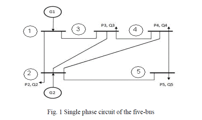
| The considered power system network is a simple five bus system, in which two buses are considered as generator buses and the remaining three buses are treated as load buses for connecting different types of loads such as static and dynamic loads is shown in fig.1. Transmission lines are modelled as a series R-L branch and the line capacitances are neglected. Generators are modelled using constant three-phase voltage source with internal impedances. Static loads are the loads; the active and reactive powers are vary with voltage with independent of time. |
 |
| The resistive loads and combination of resistive and reactive loads are treated as static loads. The loads are said to be resistive loads in which the current flows in phase the voltage given to that loads. In those particular resistive loads the active power consumption only observed. The loads are said to be inductive loads the current drawn by them is ninety degrees lag behind the supply voltage. By considering these inductive loads the reactive power consumption in the power system can be observed. |
| The combination of resistive and inductive loads causes the voltage drop across the transmission lines that mean lower voltages can be maintained at the buses where the combined loads are connected. By considering the combination of different loads the voltage variations in the power system network can be observed. The variations in the voltage levels at the buses can be studied for the analysis of voltage stability problems, which may be steady state stability or transient stability. |
| The stability problems existed in the power system by the cause of dynamic change of the voltages at the buses by the existence of dynamic loads at the buses. Any electrical power system network has to study about stability problems by treating the network is under dynamic condition. The voltage stability problems can be overcome by the consideration of Flexible AC Transmission network; this can be possible with usage of different FACTS devices in the power system network, such as shunt compensation and/or series compensation devices. The Static VAR Compensator is comes under the category of shunt compensation device to overcome the stability problems by improving the voltage levels at the buses where those compensation devices are located. |
MODELING OF STATIC VAR COMPENSATOR
|
| The modelling of SVC is based on the reactive power requirement of the network to compensate the voltage variations at the buses. SVC is a combination of thyristors and reactors and capacitors. The operation and control of SVC based on the system conditions, when the system maintained at lower voltage levels the SVC can acts as reactive power generator by deliver required reactive power to improve the lower voltage levels can be at the buses. The SVC can acts as reactive power absorber, when the voltage levels at the buses are maintained beyond the rated voltage levels. |
| The SVC device is represented by a fixed capacitor in parallel with a thyristor controlled reactor (TCR) is shown in below fig-2. The TCR consists of a fixed reactor of inductance L and a bidirectional thyristor. |
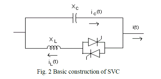 |
| The operation of the TCR is based on the firing angles given to the thyristors. By controlling the firing angles to the thyristors the current flowing through the thyristors can be controlled, hence the reactive power of the SVC can be controlled for controlling the voltage at the buses. When thyristors are fired the total reactance of the TCR is given by |
 |
| Where L is the inductance of the reactor and α is the firing to the thyristors. The thyristors are fired symmetrically in an angle control range of 90° to 180° with respect to the capacitor voltage. The total equivalent reactance of the SVC is given by |
 |
| Where xc is reactance of the capacitor and rx=xc/xl |
| The control structure of the SVC consists of Regulator Circuit Model (RCM) and Switching Circuit Model (SCM). In the RCM as shown in fig-3, RMS voltage measured at the load bus is compared with a reference voltage and the difference between them is used as the input of a PI controller. |
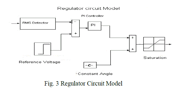 |
| The resulting output is then transferred in angle values and added constant firing angle, and then limited by a saturation block. The Switching Circuit model (SCM) is shown in fig-4 provides firing pulses to thyristors converting the angle signal that comes from the regulator circuit model. The thyristor 2 receives the pulse delayed of 180 degrees for each phase. |
 |
SIMULATION RESULTS
|
| A. Without SVC |
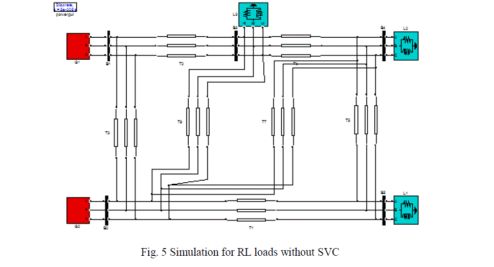
| The voltage levels at each bus have to observe by considering different loads at the buses. In this paper, a simple 5 bus system is considered. In the first case by consider RL loads at 3, 4 and 5 buses voltage levels at that particular buses will observe. In each case at which bus low voltage level is maintained has to observe. Comes to second case by connecting R-load, RLC-load, RL-load to the 3,4 and 5 buses simultaneously, the voltage levels at particular buses can be observed .In this case also at which bus low voltage level is maintained should observe. In third case the output voltages at each bus can be observe with consideration of R-load, RL-load, Dynamic loads to the 3, 4 and 5 bus locations .In this case two generators are located at buses 1 and 2, RL loads are connected at remaining buses 3, 4 and 5 is shown in below fig-5, then at each bus voltage level has to observe for obtaining low voltage bus. |
 |
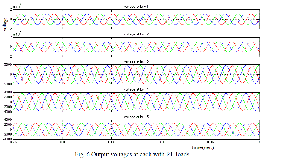
| The output voltages at each bus with RL loads are observed, is shown fig 6. By observation output voltage at bus five is maintained at lower level. Hence this is the desired location for the location of voltage compensation device. |
 |
| In similar way, as shown in fig.5 the output voltage at each bus with consideration of R, RL, RLC, Dynamic loads at 3, 4 and 5 buses respectively without any voltage compensation device has to observe. |
| In Table -1, the output voltages are given for R, RL, RLC, Dynamic loads at each bus without connecting SVC controller at any bus. |
 |
| B. With single SVC |
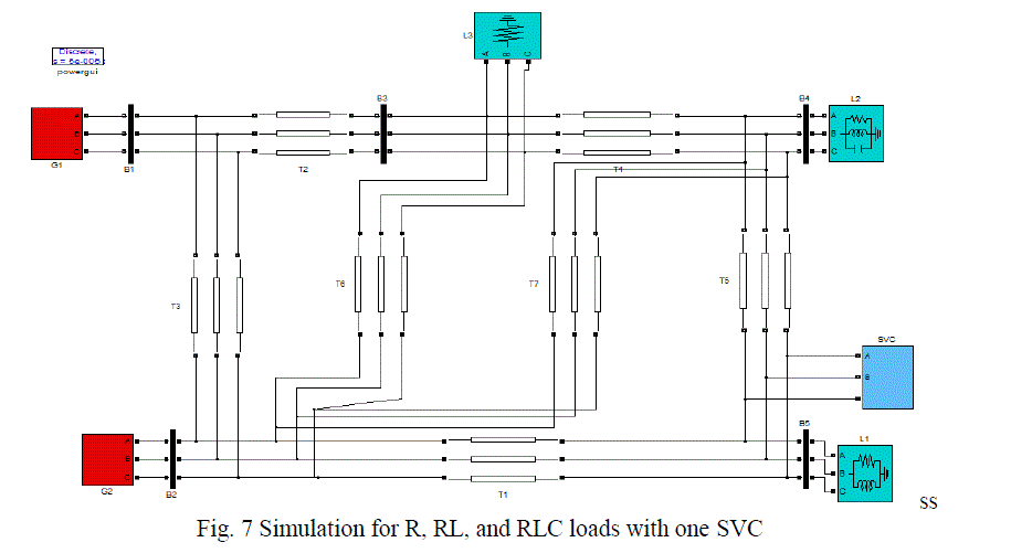
| The voltage level at the low voltage bus can be improved by placing any compensation device at that particular bus. In this paper SVC can be used for improving voltage levels by connecting at required bus. In this case R, RL, RLC loads are located at 3, 4 and 5 buses respectively in a simple five bus system is shown in below fig-7. In this case the output voltages of the load buses have to observe with a single voltage compensation device by placing at low voltage bus. |
 |
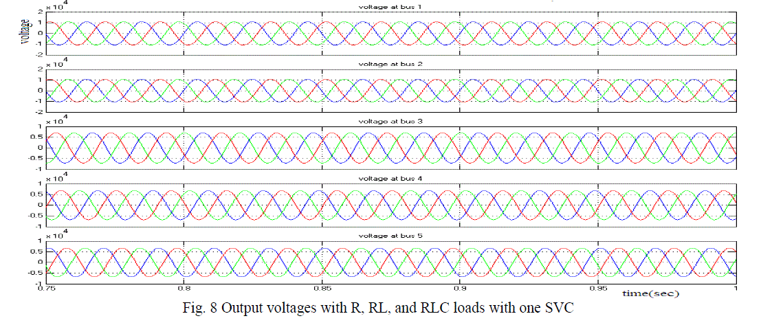
| The output voltage variations at all buses is observed with consideration of R, RL, RLC loads at the load buses is shown in below fig-8. If we observe the output voltage at bus 5 is improved by placing SVC at fifth bus compare to without SVC case. |
 |
| In similar way as shown in fig.7 the output voltages at buses with consideration of R, RL, RLC, Dynamic loads at 3, 4 and 5 buses respectively with a one SVC voltage compensation device has to observe. In Table -2, the output voltages are given for R, RL, RLC, Dynamic loads at each bus by the consideration of one SVC controller at desired bus. |
 |
| C. With two SVCs |
| In electrical network multi FACTS devices are needed, the required number of compensation devices can be placed without violating the rated voltages at the buses, where those are located. |
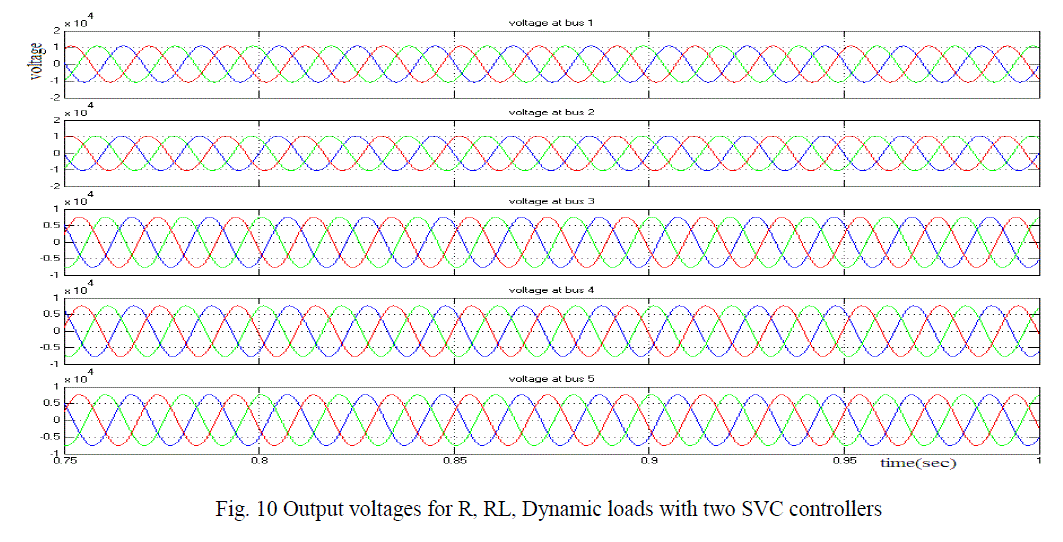
| In this particular case the loads at buses are considered as R, RL, Dynamic loads. Here the output voltage levels at load buses will observe. In this case the output voltages of the load buses are observed with two compensation devices. |
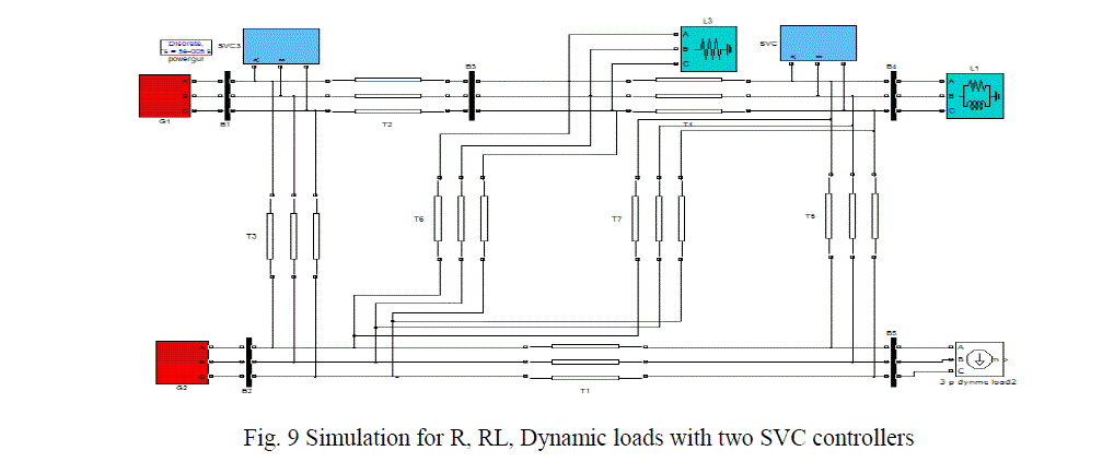 |
| The output voltages at load buses can be observed with consideration of R, RL, Dynamic loads at the buses. In this case improved voltage magnitude is maintained at all buses with two compensation devices compare to single SVC case it can be observe in below fig-10. |
 |
| In similar way, as shown fig.9 the output voltages at buses with consideration of R, RL, RLC, Dynamic loads at 3, 4 and 5 buses respectively with two SVC voltage control devices has to observe. In Table -3, the improved output voltages are given for R, RL, RLC, Dynamic loads at 3, 4 and 5 bus by consideration of two SVC controllers at desired buses. |
 |
CONCLUSION
|
| In interconnected power system different stability problems are exist. The voltage stability problem creates major effect on voltage levels at each bus. In this paper, the voltage levels at each bus for different types of loads are observed. The low voltage magnitude at any bus can be improved by placing SVC device at desired location. In this five bus system the desired location of SVC device is, at which bus low voltage level is maintained. The performance of SVC on low voltage bus with different type of loads is observed and also the effect of different locations of shunts compensators on voltage magnitude is observed. Simulation results shows that the minimum number of SVCs are located at desired location to control the system voltage at desired level under different load conditions. |
References
|
- Abe S, Fukunaga, Is ona A and kondo B., Power system voltage stability', IEEE Trans., Pas 101, 1982:3830-3840
- Borremans P, Calvaer A, De Reuuck JP, Gooses Ens J, Van Geert E, Van Hecke J, and Van Ranst A, 'Voltage stability: Fundamental concepts and comparison of practical criteria', CIGRE, 1984: 11-38.
- Cutsem TV and Vournas C, Voltage Stability of Electric Power Systems, Power Electronics and Power System Series, Kluwer, 1998.
- Pal MK, Voltage stability conditions considering load characteristics’, IEEE Trans., PWRS7,
- Karlsson D and Hill DJ, Modelling and Identification of Nonlinear Dynamic Load in Power System, IEEE Trans. on Power Systems.
- Navarro R, Dynamic Load Models for Power Systems, Lund University, Report - 2002.
- FACTS Applications’, Technical report 96TP116-0, IEEE Spectrum, 1991: 40-45.
- Canizares CA, Modelling of TCR and VSI Based FACTS Controllers, lntemal Report for ENEL and POLIMI, September 9, 1999. pp: 243-249, 1992. 0L9/l, pp.s157- 166, 1994.
- Canizares CA and Faur ZT, Analysis of SVC and TCSC controllers in voltage collapse’, IEEE Trans. On Power Systems, 1999; 14: 158-165.
- Stagg GW and AH El-Abiad, Computer methods in a power system analysis, New. Ork, MscGraw Hill, 1968.
- Faur ZT, Effects of FACTS Devices on Static Voltage Collapse Phenomena’, University of Waterloo, Ontario, Canada, Chapter 5, Report-1996.
|