Research & Reviews: Journal of Material Sciences
ISSN:2321-6212
ISSN:2321-6212
Rishav Chakraborty*
Department of Mechanical Engineering, University of Calcutta, Kolkata, India
Received: 17-Apr-2023, Manuscript No. JOMS-23-96169; Editor assigned: 19-Apr-2023, Pre QC No. JOMS-23-96169 (PQ); Reviewed: 03-May-2023, QC No. JOMS-23-96169; Revised: 19-Jul-2023, Manuscript No. JOMS-23-96169 (R); Published: 26-Jul-2023, DOI: 10.4172/2321-6212.11.4.003
Citation: Chakraborty R. Equipotential Surfaces for Uniformly Charged Symmetric Polyhedral Conductors. RRJ Mater Sci. 2023;11:003.
Copyright: © 2023 Chakraborty R. This is an open-access article distributed under the terms of the Creative Commons Attribution License, which permits unrestricted use, distribution and reproduction in any medium, provided the original author and source are credited.
Visit for more related articles at Research & Reviews: Journal of Material Sciences
In this paper the structure of equipotential surfaces of uniformly charged symmetric polyhedral conductors is discussed. It is observed that the structure of the equipotential surface is influenced more by the shape of the symmetric polyhedral conductor if it is evaluated at a smaller distance from that conductor. As we move away from the conductor, the equipotential surface becomes similar to that due to a point source, which is spherical in shape. The distance between the symmetric polyhedral conductor and the first occurrence of its spherical equipotential surface has been theoretically calculated in this paper.
Equipotential surface; Cubical conductor; Symmetric; Electric fields lines; Repulsion
Now, we know that for a uniformly charged conductor all charges reside on its surface (Figure 1).
(for simplicity one face of the cube is considered),

Figure 1: A face of the uniformly charged cubic conductor showing the distribution of charges when uniformly charged.
Equipotential surface is any surface that has an equal value of potential (in our case it will be electric potential) at every point on it (Figure 2). The surface of a uniformly charged conductor is an equipotential surface [1,2.

Figure 2: Equipotential surface due to a point charge.
Research gap
In previous research papers the concept of the curvature of equipotential surfaces at sharp bends for cubical conductor has been discussed. No theory regarding the equipotential surface of other polyhedral conductors has been proposed. The concept of the curvature of equipotential surface at sharp bends of uniformly charged conductors and it becoming spherical at far fields has been explained in previous research papers using concepts which might be unfamiliar to high school students. The distance between the conductor and the first occurrence of its spherical equipotential surface has never been derived. The aim of this paper is to explain the dynamics of equipotential surfaces of various symmetric polyhedral conductors in more simple way for the reader to understand [3-5].
The curvature of equipotential surfaces at sharp bends of uniformly charged symmetric polyhedral conductors
Each face of the uniformly charged symmetric polyhedral conductor is like a charged conducting surface and for a charged conducting surface the electric fields lines due to it are normal to its surface whereas the charges at the sharp bends and corners have their electric field lines radially outwards.
If the face of the uniformly charged polyhedral conductor is divided into individual points, then each point will behave as point charge with its electric field lines projecting radially outwards. As the nature of the electric field of the individual are similar, there will be repulsion between the electric field lines of the individual points (Figures 3 and 4).
As inside the charged conductor the net electric field is always zero, the side of the face inside the conductor is neglected [6].

Figure 3: a) Electric field lines of the individual points initially when they are far enough; b) Repulsion between the electric field lines results in them bending away from each other as the individual points get closure; c) Repulsion causes the electric field lines to bend more; d) When the points get close enough the repulsion increases so much that from each individual point a single electric field line projects out perpendicular to the surface thus formed by bringing the individual points together.

Figure 4: Shows Electric field lines at the sharp bends of the charged polyhedral conductor.
We know that:
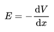
Where V is the electric potential, E is the electric field due to the charge and x is the distance from the charge.
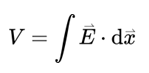
For equipotential surfaces V is constant, so work done=0, i.e., Electric field is perpendicular to the surface (Figure 5).

Figure 5: Electric field and equipotential surface due to a uniformly charged cubic conductor (for simplicity 2-D figure of a cube is considered).
The conductor’s surface is itself an equipotential surface and as we move away from the conductor’s surface, more cubical equipotential surfaces are formed with curved vertices (Figures 6-10). And with increase in distances the vertices curve to such an extent that the equipotential surface then resembles a spherical equipotential surface [7-9].

Figure 6: Equipotential surface of the cubic conductor of edge a and at a distance of x from the cube’s charged surface.

Figure 7: At the vertex the equipotential surface looks like an arc of a circle’s quadrant of radius x.
Now let’s consider a symmetric tetrahedral conductor:

Figure 8: A symmetric tetrahedral conductor.

Figure 9: Electric field and equipotential surface due to a uniformly charged symmetric tetrahedral conductor.

Figure 10: Equipotential surface of the cubic conductor of edge a and at a distance of x from the tetrahedron’s charged surface.
In Figure 10, we can see that at the vertex part the equipotential surface looks like the arc of a sector of a circle of radius x subtending an angle of 120 degrees.
In a research paper on “the electric field of a uniformly charged non-conducting cubic surface” it was concluded that “the electric field magnitude can diverge to infinity for a charge distribution that has a sharp bend like the edges of the uniformly charged cubic surface. This can happen even though the charge density does not itself diverge in magnitude near an edge or vertex, as is the case for a charged conducting surface with a sharp bend”.
Occurrence of spherical equipotential surface for polyhedral conductors (Figure 11).

Figure 11: Transition of the equipotential surface of the cubic conductor from a cubical structure to a spherical structure.
x=radius of the small quadrant at the vertices.
R=radius of the large quadrant of the spherical equipotential surface.
As x increases from from its initial point P on the vertex to R, from the perspective of the consecutive equipotential surfaces the cube shrinks in size and the point P shrinks from zero to a/2 for the spherical equipotential surface.
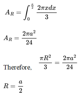
As x increases from zero (taken from a vertex ‘P’) to R by a length of dx (very small change in x), the area of the small quadrant increases and finally becomes equal to the area of the large quadrant.
Area of the small quadrant be ‘Ax’
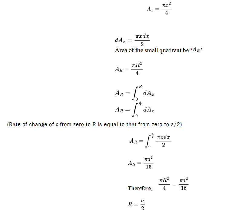
Distance between the center of a uniformly charged cubic conductor and its spherical equipotential surface=distance between the center and a vertex+distance between the vertex and its spherical equipotential surface=(√3a/2)+(a/2) (Figure 12).

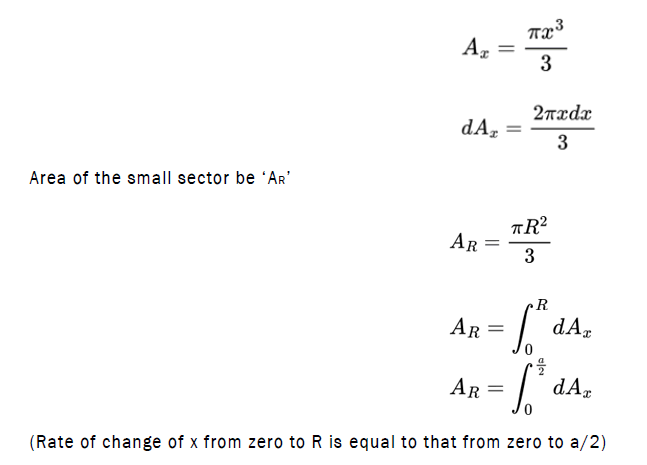
Figure 12: Transition of the equipotential surface of the tetrahedral conductor from a tetrahedral structure to a spherical structure.
x=radius of the small sector at the vertices.
R=radius of the large sector of the spherical equipotential surface.
As x increases from its initial point P on the vertex to R, from the perspective of the consecutive equipotential surfaces the tetrahedron shrinks in size and the point P shrinks from zero to a/2 for the spherical equipotential surface.
As x increases from zero (taken from a vertex ‘P’) to R by a length of dx (very small change in x), the area of the small sector increases and finally becomes equal to the area of the large sector.
Area of the small sector be ‘Ax’
Theory
For a uniformly charged symmetric polyhedral conductor where length of a side is ‘a’, its equipotential surface curves at the vertices as we move away from it and finally becomes similar to a spherical equipotential surface and the diagonal distance between its vertices and the first occurrence of its spherical equipotential surface is equal to half of ‘a’.
Let ‘R’ be the diagonal distance between the vertices of the uniformly charged symmetric polyhedral conductor and its first occurrence of its spherical equipotential surface.
Then,

Relation between r and the number of vertices and faces of a polyhedral conductor
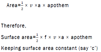
The surface area of a polyhedron is equal to the sum of the area of all of its faces.
Let the number of faces of the uniformly charged symmetric polyhedral conductor be ‘f’
Surface area=f × area
and the area of one face of a symmetric polyhedron= × (perimeter) × (apothem)
(apothem=distance between the centre of a face of a polyhedron and one of its sides)
Let the number of sides of one face of a symmetric polyhedron be ‘s’, the no of vertices of one face of a symmetric polyhedron be ‘v’ and ‘a’ be the edge length.
For a face of a symmetric polyhedron, v=s
Perimeter of one face of a symmetric polyhedron=s × a
=v × a
Comparing R for a cubic and a tetrahedral conductor:
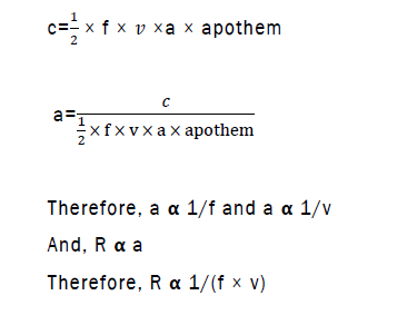
Keeping the surface area of both the polyhedral conductors equal to 1,
v and f for cubic conductor is 8 and 6 respectively
v and f for tetrahedral conductor is 4 and 4 respectively
(v × f) for cubic conductor is 48
(v × f) for tetrahedral conductor is 16
v × f (cubic)>v × f (tetrahedral)
As R∝ 1/(f × v)
Therefore, R (cubic)<R (tetrahedral)
Now, keeping the surface area of the both polyhedral conductors equal to 1 m2,
a for cubic conductor is 0.408 m
a for tetrahedral conductor is approx. 0.76 m
R (cubic)=a/2=(0.408 m)/2=0.204 m
R (tetrahedral)=a/2=(0.76 m)/2=0.38 m
R (cubic)<R (tetrahedral) (proved)
Theoretical proof
Here, R is inversely proportional to v.
If v→∞,
Then, R→0, according to the theory.
Now we know that a sphere is a polyhedron where v→∞ and its vertices connect and form a spherical surface.
And for a uniformly charged spherical conductor its first spherical equipotential surface is its own surface, hence the R in this case becomes zero.
In this paper, I have explained how the equipotential surface is influenced by the shape of the symmetric polyhedral conductor and how it finally becomes spherical as it would be if the polyhedral conductor is replaced by a point charge placed at the center of that conductor. As we move away from the polyhedral conductor the consecutive equipotential surfaces curve more at the sharp bends. A pattern is observed when the diagonal distance from the vertex of the conductor to the first occurrence of its spherical equipotential surface for all symmetric polyhedral conductors is mathematically calculated which is half of the length of its side.
[Crossref] [Google Scholar] [PubMed]
[Crossref] [Google Scholar] [PubMed]
[Crossref] [Google Scholar] [PubMed]
[Crossref] [Google Scholar] [PubMed]
[Crossref] [Google Scholar] [PubMed]