ISSN ONLINE(2278-8875) PRINT (2320-3765)
ISSN ONLINE(2278-8875) PRINT (2320-3765)
R.K.Dhatrak1, Dr.D.M.Deshpande2 and Dr.R.K.Nema2
|
| Related article at Pubmed, Scholar Google |
Visit for more related articles at International Journal of Advanced Research in Electrical, Electronics and Instrumentation Engineering
Application of modern inverter topologies allows high dynamic operation of the variable speed drives with savings in energy. However fast switching frequency and high dv/dt introduces disadvantages like common mode voltages and shaft voltages which results in bearing currents. The lubricating film in the bearing acts as a capacitor that charges due to the transition in common mode voltage. This capacitor provides a charging mechanism to build up rotor shaft voltage. If this shaft voltage exceeds threshold value breakdown of the film takes place which causes current spikes. This electrical breakdown of film causes mechanical damage to the bearing. Parasitic coupling model over a wide range of frequencies is used for evaluation of shaft voltage and common mode voltage. In this paper shaft voltages and common mode voltages with two and three level inverter has been evaluated and compared. This circuit model can be used to evaluate the effects of two and three level inverter on shaft voltage and common mode voltage using MATLAB Simulink. This document gives formatting instructions for authors preparing papers for publication in the Proceedings of an International Journal. The authors must follow the instructions given in the document for the papers to be published. You can use this document as both an instruction set and as a template into which you can type your own text.
Keywords |
| Bearing current, common mode voltage, inverter and shaft voltage |
INTRODUCTION |
| This document is a template. An electronic copy can be downloaded from the conference website. For questions on paper guidelines, please contact the conference publications committee as indicated on the conference website. Information about final paper submission is available from the conference website. |
| Bearing currents and shaft voltages have been identified since 1924 [1]. The main cause for this was asymmetric flux distribution inside the motor which leads to an induced voltage across the rotor shaft [2]-[4]. At low frequency, chances of occurrence of this fault is very less. Before 1980 it was supposed that the bearing current problems are mainly due to electromagnetic induction. It becomes a prominent problem after the application of recently developed semiconductor devices in drives [5]. |
| Use of semiconductor devices rapidly increases in drives after 1990. Modern fast switching devices gives a very dynamic operation of variable speed drives. This also saves energy of the system. Due to application of these devices the switching time becomes very less this gives rise to high dv/dt. At the same time it gives rise to: |
| 1) Ground current through stray capacitors |
| 2) Conducted and radiated EMI |
| 3) Bearing current and shaft voltages |
| Bearing current of line operated electrical machine without inverter is called as classical bearing current. This current has been investigated in 1924 by Alger. All rotating machines whether ac or dc suffers from this problem. These rotating machines have three main sources of shaft voltages. They are electromagnetic induction, electrostatic coupled from the internal sources and electrostatic coupled from the external sources. Introduction of fast switching power semiconductor devices into the drive system improves the performance of system. On the other hand premature bearing damages have been observed as a result of some inverter topologies [2]. |
| Common mode voltage (CMV) is the prime drawback of two level inverter. It is the main cause to develop shaft voltages and hence premature failure of bearings [9]. It is important to reduce CMV or to keep this voltage within a certain specific limits. Some approaches to reduce CMV include four leg inverters, passive filters, passive elements with active circuitry and dual bridge inverters. A multilevel inverter is the best option to reduce CMV. The incremental steps in CMV in multilevel inverters are smaller since it has high number of switching states. Five level inverter even eliminates the CMV if proper switching sequence is used. It has 125 combination of switching states. Out of these 19 combinations generates zero CMV [10]. |
| At present the H-bridge multilevel inverters are being used commonly in industrial applications for high power drives. The main drawback of these inverters is that they require a large number of dc sources or isolation transformers on ac sides. The diode clamped multilevel inverter is appropriate for medium and high power drives. This inverter needs only one dc power supply. Therefore it is appropriate for industrial drives. |
| In this paper CMV and shaft voltage are evaluated on same model using two level and three level inverters. Then they are compared. In [6] PSpice software only with two level inverter has been used for comparison. In this paper these are compared using MATLAB simulink. |
PARASITIC COUPLING IN INDUCTION MOTOR |
| At high frequencies the parasitic coupling between the windings to stator and rotor are developed. These are usually considered as lumped networks. These lumped parameters may be estimated at a specific frequency or may be chosen over a range of frequencies. In this paper the lumped network have been chosen over a range of frequencies. The four main parasitic impedance networks considered are - 1)Zsf, stator winding to frame impedance, 2) Zg, air gap impedance, 3) Zsr stator winding to rotor impedance and 4) Zb the bearing impedance [6]. It is assumed that the bearing balls float in the lubricant and do not touch either of bearing races. |
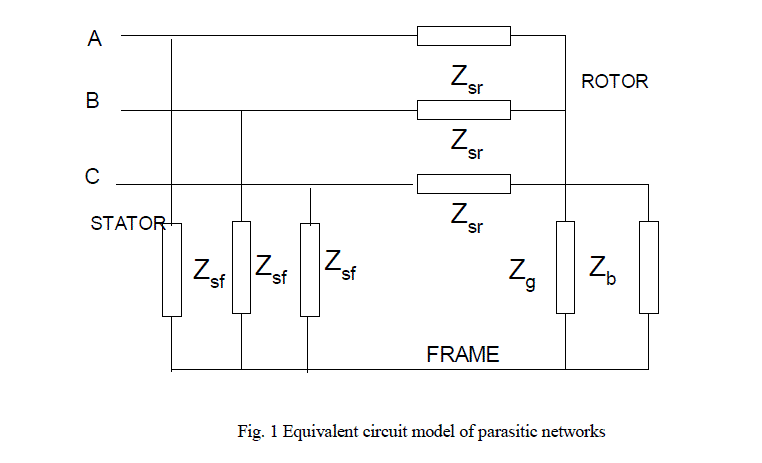 |
| Fig. 1 is the equivalent circuit of motor considering four parasitic impedance networks. The magnitude of shaft voltage Vsh and common mode voltage Vcom with respect to Fig. 1 is given by (1) and (2) respectively. |
 |
| VAN, VBN and VCN are voltages of stator winding with respect to ground. |
MODEL DEVELOPMENT |
| The sub circuits are developed by impedance measurements performed on test motor based on the ideas given in [2]-[5]. In this parameters are measured over a range of frequencies. The measured magnitude and the phases of Zsf, Zsr and Zb can be plotted for a range of frequencies. Then sub circuits for these impedances can be developed [6]. The model is developed for 3-phase, 400 volt, 30hp, 4-pole, 50 Hz. |
| A. Stator Winding to Frame Impedance Zsf |
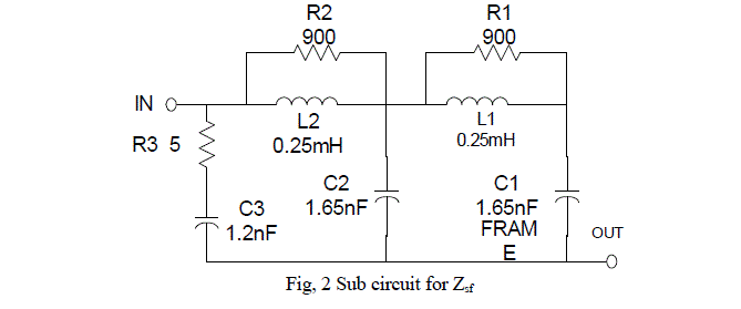
| Rotor is removed and the impedance between the three stator winding and the frame is measured over a range of frequencies. From the measured value the circuit used for the simulation is developed asshown is in Fig, 2. |
 |
| B. Air Gap Impedance Zg |
| This is calculated by considering a flat parallel plate capacitor. For 30 hp motor it is found to be 0.86 nF. It is purely in capacitive nature. |
| C. Stator winding to rotor impedance Zsr |
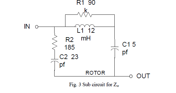
| It cannot be measured directly. It can be calculated using previous two impedances and measuring the impedance between shorted stator winding terminals and the rotor. LCR meter is used for this measurement. The impedance measured by the LCR meter is given by (3). |
 |
| By knowing other parameter Zsr can be calculated from equation (3). The sub circuit for Zsr is as shown in Fig, 3. |
 |
| D. Bearing Impedance Zb |
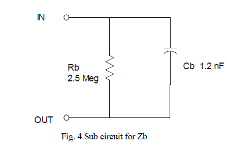
| It is considered as a parallel combination of a capacitor and a high resistor. Bearing impedance depends upon number of factors such as temperature, speed, lubricant viscosity etc. These are not taken into account in this paper. LCR meter is used to measure impedance between inner and outer race of the bearing. The sub circuit for calculation of Zb is as shown in Fig. 4. |
 |
TECHNIQUES FOR THE MEASUREMENT OF BEARING CURRENTS AND SHAFT VOLTAGES |
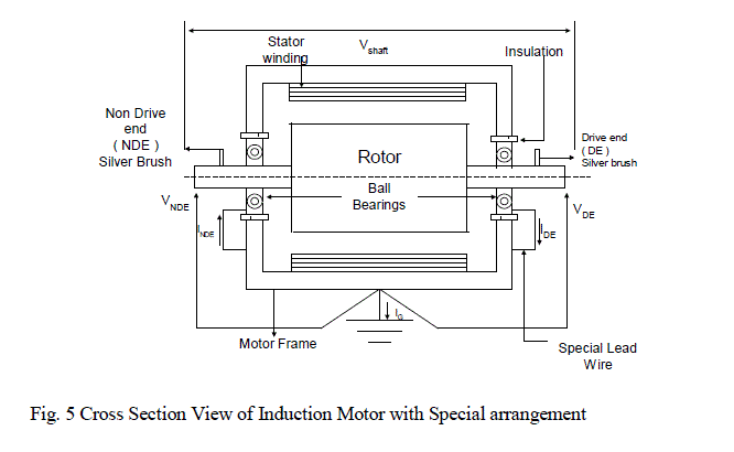
| A proper measurement technique is necessary for any investigation. One specially designed motor Fig. 5 is used to measure bearing current and shaft voltage. |
| A. Measurement of Bearing current |
| Bearing current cannot be measured inside the bearing due to its high frequency nature. Therefore it should be measured as close to the bearing as possible. Inner race of the bearing on both shaft end is electrically and mechanically connected with the shaft. Outer bearing race on both shaft ends is isolated from the motor frame by inserting an insulating material. To measure circulating bearing current a special wire is connected from the bearing outer race to motor frame as shown in Fig. 5. |
| B. Measurement of bearing voltage |
| Two carbon or silver brushes are pressed on two shaft ends. With these brushes it is possible to measure the shaft voltage between two end bearings. These brushes are also useful to measure both drive end and non-drive end shaft to frame voltages [7]. |
 |
SIMULATION MODEL WITH TWO LEVEL INVERTER |
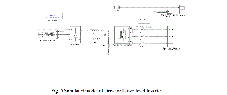
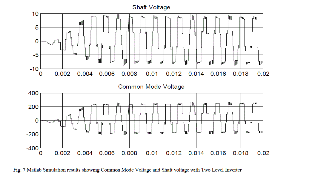
| Simulated model shown in Fig. 6 has been used to evaluate shaft voltage and common mode voltage using MATLAB simulink. The circuit consists of three phase diode bridge rectifier, dc link capacitor and inductors. DC bus is connected to insulated-gate-bipolar-transistor based inverter. Inverter receives its switching signals from PWM controller. Inverter controls an induction motor. The induction motor model which is used for calculating the shaft voltage is connected to the motor terminals. Zsf is not used for calculating the shaft voltage but it is taken into account to estimate the total ground current. Simulation results of shaft voltage and common mode voltage are shown in Fig. 7. It is observed that shaft voltage is the mirror image of common mode voltage. The magnitude of shaft voltage and common mode voltage estimated from the simulation is varying between 9 to 10 volts and 245 to 266 volts respectively. The ratio of shaft voltage to common mode voltage varies between 1/27.22 to 1/26.6. The shaft voltage is about 1/33-1/25 of the common mode voltage [6]. This is very close to the actual values found in simulations. |
 |
 |
THREE LEVEL INVERTER |
| Three level inverter has advantages of having low harmonics distortion, low switching frequency and low common mode voltage and hence less requirement of filtering circuits. It consists of capacitors, switching devices, dc voltage source and clamping diodes. Middle point of two capacitor is defined as neutral point. The output voltage has three levels Vdc/2, 0 and -Vdc/2. |
| The common mode voltage can be reduced by modification in control techniques applied such as [11] |
| 1. Space vector PWM techniques (SVPWM) |
| 2. Sinusoidal PWM techniques (SPWM) |
| SVPWM technique is complicated as compared to SPWM. |
| The various alternative carrier disposition SPWM techniques are [8]-[10] |
| 1) All of the carriers are in phase disposition (PD) |
| 2) All of the carriers above the zero reference are in phase, but in opposition to those below (POD) |
| 3) All the carriers are alternatively in opposition disposition (APOD) |
SIMULATION MODEL WITH THREE LEVEL INVERTER |
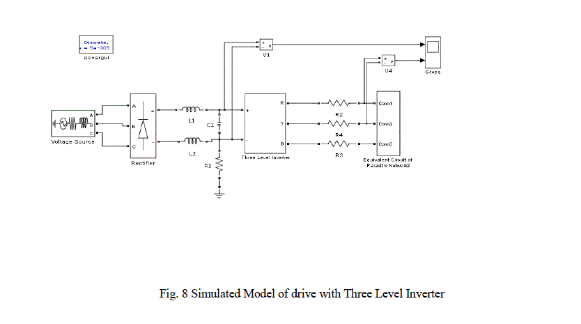
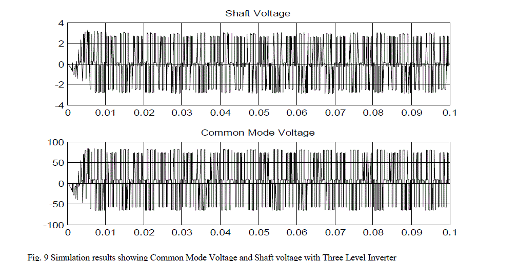
| It is found that in two level inverter value of shaft voltage is nearly 10 volts and common mode voltage is nearly 260 volts. It is observed that shaft voltage is mirror image of the common mode voltage at every point. In order to reduce common mode voltage and shaft voltage an attempt is made to use simple diode clamped three level inverter instead of usual two level inverter as shown in Fig. 8. It is found that results are quiet improved. Shaft voltage varies between 2.7 to 3 volts and Common mode voltage voltage varies between 74 to 81 volts. Same motor model is used for the analysis of two inverters. The circuitry is also same only the change is inverter model. Here attempt is made using simple three level inverter. Simulation results of Common mode voltage and shaft voltages are shown in Fig. 9. The ratio of shaft voltage to common mode voltage varies between 1/27.4 to 1/27. It means by using three level inverter shaft voltage and common mode voltages are reduced in same proportion. |
| In three level inverter also common mode voltage and shaft voltage remains present but their magnitudes are reduced. To reduce them still further proper common mode and differential mode filters have to be used. Some special modulation techniques are also used to reduce these. |
 |
 |
CONCLUSION |
| It is observed through simulation studies that three level inverter reduces the shaft voltage and common mode voltage but are not nullified fully. So for reducing it to zero either filters or mdified modullation techniques have to be used. Common mode voltage can also be reduced by increasing level of the inverter. Use of three level inverter reduces common mode voltage and shaft voltage in same proportion.Hence their ratio in both cases nearly remains same. Using same procedure simulation model for different motor can be designed. The model is suitable for use in circuit simulation like MATLAB, PSPICE etc. Application of this model to the circuit is very simple. System elements can be varried to study their effects on shaft voltage and common mode voltage. |
References |
|