Keywords
|
| Transverse vibrations, Free-free beam, Young’s modulus, Continuous systems |
INTRODUCTION
|
| Vibrations can be described as a linear combination of the modes of a structure. An alternative is to describe vibrations as propagating waves travelling in the structure. It was found that the two descriptions often give informative corresponding perspectives. Wave propagation, transmission and reflection in solids have been studied by a number of researchers [1]. |
| An exact formulation of the beam problem was first investigated in terms of general elasticity equations by Pochhammer (1876) and Chree (1889). They derived the equations that describe a vibrating solid cylinder. However, it is not practical to solve the full problem because it yields more information than usually needed in applications. Therefore, approximate solutions for transverse displacement are sufficient. The beam theories under consideration all yield the transverse displacement as a solution. |
| Early researchers concluded that the bending effect is the single most important factor in a transversely vibrating beam. The Euler Bernoulli model includes the strain energy due to the bending and the kinetic energy due to the lateral displacement. Jacob Bernoulli in 1654-1705 first discovered that the curvature of an elastic beam at any point is proportional to the bending moment at that point. After this Daniel Bernoulli in 1700-1782, who formulated the differential equation of motion of a vibrating beam. [2] |
| Understanding the change in material properties in time is necessary for in-service diagnosis of structures and prevention of accidents. [3] Therefore, they presented a new experimental technique for evaluating Young’s modulus of a vibrating thin sheet from dynamic considerations. The technique utilizes bending resonance from a remote acoustic excitation equations relating the natural frequencies to the mechanical properties are obtained, and Young’s modulus is subsequently determined experimentally using the implemented dynamic measurement method |
| Beam theory which adds the effect of shear as well as the effect of rotation to the Euler-Bernoulli beam. The Timoshenko model is a major improvement for non-slender beams and for high-frequency responses where shear or rotary effects are not negligible. Following Timoshenko, several authors have obtained the frequency equations and the mode shapes for various boundary conditions. [4] |
DESIGN AND EXPERIMENTATION
|
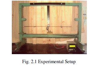
| The experimental setup shown in Fig. 2.1 is used for the present study consists of a rigid rectangular frame. The sidewaysare fixed on the top side and the exciter unit is fixed on the bottom side of the frame. The wire supports are given to the beam which is placed at a distance of 212mm from each end. The plunger of the exciter is attached to bottom of the beam centrally. The potentiometer is attached to the slider which can be slide along the length of the beam. The probe is attached to the potentiometer which is kept in the contact of beam. The variable frequency inverter is used to vary the frequency of vibration during the experiment. The amplitude of vibration sensed by potentiometer is displayed on the display unit. |
| In this experimentation assumptions are made that the beam is linear and all properties are uniform. Beam is excited at different frequencies sweeping the range from low frequencies (about 2 Hz) to high frequencies (up to 35 Hz). For each excitation frequency the amplitude of a vibration by moving the potentiometer along the length of beam is measured. From the measured amplitude values at various points,practical profile of the given vibrating beam is drawn and compared with theoretical, numerical and analytical profile. |
| Specifications of Experimental Setup |
| l=Length of Beam : 950 mm |
| b=Width of Beam : 25 mm |
| t=Thickness of Beam : 6 mm |
| Material of Beam : Spring Steel |
| ρ=Density of Beam Material : 7800 kg/m3 |
 |
RESULT AND DISCUSIONS
|
| Theoretical Analysis: |
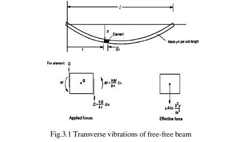
| The transverse or lateral vibration of a thin uniform beam is another vibration problem in which both elasticity and mass are distributed. Consider the moments and forces acting on the element of the beam shown in Fig.3.1. The beam has a cross-sectional area A, flexural rigidity EI, material of density ρ and the shear force isQ. [5] |
 |
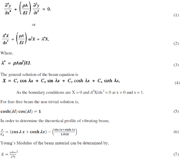
| The general equation for the transverse vibration of a uniform beam is |
 |
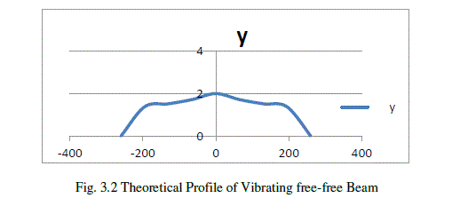 |
| Fig.3.2shows the variation of amplitude (y)vs distance of measuring point from centre(x) theoretically. The amplitude changes with change in distance of a measuring point from the centre of the beam. |
| Experimental Analysis: |
| The beam is excited at different frequencies sweeping the range from low frequencies (about 2 Hz) to high frequencies (up to about 35 Hz). For each excitation frequency measure the amplitude of a vibration by moving the potentiometer along the length of beam. From the measured amplitude values at various points, draw the practical profile of the given vibrating beam. With the help of above formulae find out analytically the profile of given vibrating beam. |
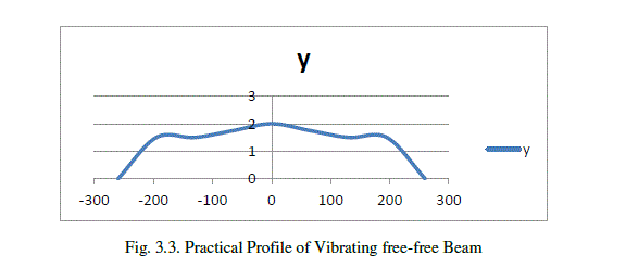 |
| Fig.3.3shows the variation of amplitude (y)vs distance of measuring point from centre(x) practically. The amplitude changes with change in distance of a measuring point from the centre of the beam. |
| Numerical Analysis: |
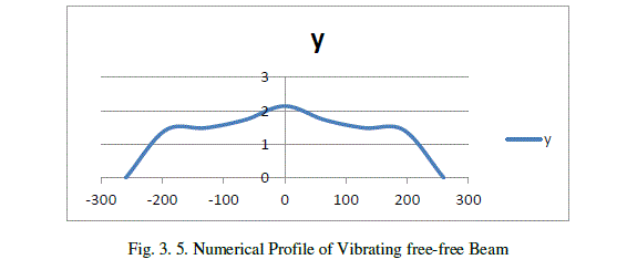
| ANSYS structural package is used to analyze the vibration of free-free beam. At present finite element procedures very widely used in engineering analysis. The procedures are employed extensively in the analysis of solid and structures and of heat transfer and fluids and indeed, finite element methods are useful in virtually every field of engineering analysis. [6] |
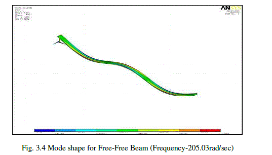
| In the numerical analysis, ANSYS software is used as a tool for finding mode shapes of free-free beam. Total 20 modes are extracted using Block Lanczos method of Modal Extraction.Fig.3.4 shows the mode shape for free-free beam at fundamental frequency(205.03rad/sec). |
 |
| Fig.3.5 shows the variation of amplitude (y) vs distance of measuring point from centre(x) numerically. The amplitude changes with change in distance of a measuring point from the centre of the beam. |
 |
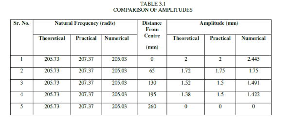
| Table 3.1 shows the variation of amplitude (y) vs distance of measuring point from centre(x) theoretically, practically and numerically. |
 |
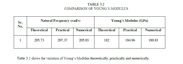 |
| Table 3.2 shows the variation of Young’s Modulus theoretically, practically and numerically. |
| From the results obtained, it is seen that, the theoretical and numerical values of natural frequency and young’s modulus are away from practical values by 0.79 to 1.12 % and 1.6 to 2.24 % respectively. As practical analysis accounts for all types of nonlinearities, it is essential to carry out theoretical and practical analysis by considering all types of non-linearity’s in order to improve its performance. |
CONCLUSIONS
|
| In this work, free-free model for a transversely vibrating beam which is Euler-Bernoulli model is examined. A governing equation of transverse vibration is derived from Euler-Bernoulli theory. Under the assumption that the system is linear and the material properties are isotropic. |
| The rectangular cross section of a free-free beam was analyzed and the natural frequencies and Young’s modulus were calculated. There is small variation in profiles of beam as well as value of Young’s modulus may be due to variation in material properties (material non-linearity and small amount of damping (contact non-linearity)) and small amount of damping in system during the experimentation. |
| Variation in amplitude and value of young’s modulus for Theoretical, Numerical and Practical analysis may be due to nonlinearity’s in the systems, but effects of these nonlinearity’s are not considered in Theoretical and Numericalanalysis. |
| |
References
|
- Mansour Nikkhah-Bahrami, MasihLoghmani, and MostafaPooyanfar “Analytical Solution for Free Vibration of Rectangular Kirchhoff Plate from Wave Approach”, World Academy of Science, Engineering and Technology 39, pp 221-223,2008.
- ShahrokhHosseineHashemi,AlirezaRamezani, KoroshKhorshidi.“The Effects of Step, Ramp And Sinusoidal Forces on Response of Multi Step Timoshenko Beam”,Impact Lab., Department of Mechanical Engineering, Iran University of Science and Technology (IUST),Iran.
- E. Mfoumou, S. Kao-Walter, and C. Hedberg, “Remote Acoustic Monitoring of Thin Laminates”,The 2nd World Congress on Engineering Asset Management (EAM) and The 4th International Conference on Condition Monitoring, pp1426-1433.
- Seon M. Han, HaymBenaroya and Timothy Wei, “Dynamics of Transversely Vibrating Beams Using Four Engineering Theories”,Journal of Sound and vibration pp. 935-988,1999.
- S. S. Rao, Mechanical Vibrations, 3rd ed. Addison-Wesley Publishing Company (1995).
- J.P. Chopade, R.B. Barjibhe, “Free Vibration Analysis of Fixed Free Beam with Theoretical and Numerical Approach Method”, International Journal of Innovations in Engineering and Technology (IJIET), Vol. 2 Issue 1,pp 352-356, February 2013.
|