Keywords
|
| SCADA, Expert system, ECG, Data Acquisition system, Respiration temp, heart beat sensor |
INTRODUCTION
|
| Modern Expert and SCADA Based Centralized Patient Monitoring and Escorting System is truly sophisticated, this can be done by aided of hardware Bio-medical equipment with the computer control SCADA..In this paper mainly the following parameters can be considered. |
| 1. Body temperature, 2. Respiration rate, 3. Heart beat, 4. ECG signal, 5. Guidelines by Expert, 6.Alarm. |
| Body temperature: human body has the remarkable capacity for regulating its core temperature somewhere between 98°F and 100°F when the ambient temperature is between approximately 68°F and 130°F according to Guyton. Here the body temperature is measured by thermistor type of sensor. |
| Respiration rate: The respiration rate is the rate at which a person breathes. It increases with fever and some illnesses. The best time to count the respiration rate is when a person is resting, perhaps after you take the person's pulse while your fingers are still on the person's wrist. The person's breathing is likely to change if he or she knows you are counting it [2]. |
| Normal resting breathing rate: New born to 6 months: 30–60 breaths per minute,6–12 months: 24–30 breaths per minute,1–5 years: 20–30 breaths per minute,6–12 years: 12–20 breaths per minute,12 years and older: 12–20 breaths per minute. |
| Heart beat: here the heart rate can be measured by using IR type sensor. Heart rate, or heart pulse, is the speed of the heartbeat measured by the number of heartbeats per unit of time — typically beats per minute (bpm). Athletes who have done a lot of training may see their resting heart rate fall below 60 beats a minute, possibly to as low as 40 beats a minute[5]. The following list shows how heart rate (in beats a minute) gradually slows down through young childhood. First month of life - 70-190 ,Between 1 and 11 months - 80-160 ,One- and two-year-olds - 80-130 ,Three- and fouryear- olds - 80-120 ,Five- and six-year-olds - 75-115 ,Between seven and nine years - 70-110 ,From 10 years of age - 60-100. |
| ECG signal: In this paper ECG can be recorded by the electrodes arrange in proper way. Electrocardiogram (ECG) is widely used for diagnosis of heart diseases. Good quality ECG is utilized by physicians for interpretation and identification of physiological and pathological phenomena. |
 |
| Fig 1.expert system |
| Alarm: whenever the patient body conditions exceed the normal conditions then the alarm will be on. |
| This paper mainly has as follows. Segment I Introduction to bio medical parameters like body temperature, respiration |
| rate, pulse rate, ECG signals and techniques used for Measurement of bio medical parameters |
| Segment II: Block diagram of the application considered |
| Segment III: bio-medical sensors and signal conditioning circuits. |
| Segment IV: PIC 16F877 microcontroller interfacing. |
| Segment V: SCADA USING VISUAL BASIC 6.0 |
| Segment VI: result-SCADA screens |
| Segment VII: references. |
LITERATURE SURVEY
|
| I studied so many biomedical papers regarding patient monitoring like secure remote patient monitoring system [12], A Microprocessor based system for ECG Telemedicine and Telecare [13] and Bluetooth telemedicine processor for multichannel biomedical signal transmission via mobile cellular networks, These papers describes only the monitoring of patient body conditions and telecare systems then i thought that if the patient condition is severe while the absence of the doctor then how to protect the patient then i got an idea of Expert and SCADA Based Centralized Patient Monitoring and Escorting System. This paper mainly describes how to protect the patient from the severe conditions while absence of the doctors. |
BLOCK DIAGRAM OF THE APPLICATION
|
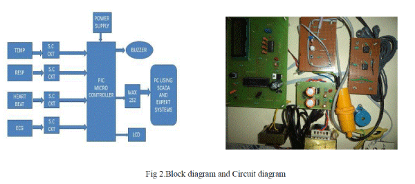
| Block diagram and circuit diagram are shown in fig.2.It completely describes the expert and SCADA based centralized patient monitoring and escorting system. Here we are interfacing four Bio-medical sensors to the PIC16F877 microcontroller [3]. PIC16F877 microcontroller is interfaced with SCADA using RS-232 to USB cable by using respective drivers. The micro controller requires the power supply of 5V; it is given by using switched-mode power supply. Every sensor output is given to particular signal conditioning circuit to provide the sufficient voltage range of the signals to the controller. |
| Apart from a large number of digital I/O lines, the PIC16F887 contains 14 analog inputs. That means we can interface analog inputs directly to the controller. They enable the microcontroller to recognize, not only whether a pin is driven to logic zero or one (0 or+5V), but to precisely measure its voltage and convert it into a numerical value, i.e. digital format. The whole procedure takes place in the A/D converter module which has the following features. |
| 1.The converter generates a 10-bit binary result using the method of successive approximation and stores the conversion results into the ADC registers (ADRESL and ADRESH); |
| 2 There are 14 separate analog inputs; |
| 3 The A/D converter allows conversion of an analog input signal to a 10-bit binary representation of that signal; |
| 4 By selecting voltage references Vref- and Vref+, the minimal resolution or quality of conversion may be adjusted to various needs. |
 |
| ADC Mode and Registers: Even though the use of A/D converter seems to be very complicated [8], it is basically very simple, simpler than using timers and serial communication module, anyway. The module is under the control of the bits of four registers. |
| ADRESH - Contains high byte of conversion result. |
| ADRESL - Contains low byte of conversion result. |
| ADCON0 - Control register0. |
| ADCON1- Control register1. |
| In this project we have two display units. One is SCADA display unit and another one is LCD display unit. Here two display units display the parameters of human body but SCADA system displays all the parameters at a time in the form of graphs, records and tables. It provides the historical data of the patient and it is mainly acting as Expert system. Here LCD display is mainly used for calibration purpose and also for safety purpose even though SCADA fails. |
| Whenever the patient body parameters (bio-medical parameters) exceed the normal value then the buzzer will be on. Buzzer is controlled by the PIC controller.PIC microcontroller is interfaced to the PC or SCADA system through MAX232 by using RS-232 to USB connector. Drivers could be installed to read the configuration of the controller then only read the data from the controller to PC memory. The most difficult part of this project was learning exactly what was required to get the PIC microcontroller to communicate with the USB port. The two most important things that absolutely have to be correct are the microcontroller configuration, and the USB device descriptor. If even the smallest |
| thing is incorrect about either of these, communication will not occur. Even before programming the microcontroller, its configuration must be correct. In micro BASIC Pro this is accomplished by editing the project. |
BIO-MEDICAL SENSORS AND SIGNAL CONDITIONING CIRCUITS
|
| The devices which are interfaced to PIC micro controller PIC16F877 that device signals could be conditioned. The following devices are used to measure the bio-medical parameters of the human body. |
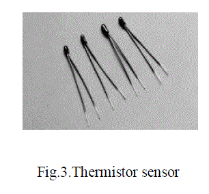
| Thermistor sensor: here we are using disk type thermistor as shown in fig.3 Thermistor sensors are used mostly for room temperature measurement up to moderately high temperatures [9]. The great advantage of thermistors is their high sensitivity. They are popular in research and in medical applications, e.g. as electronic medical thermometers. Low cost solid state sensor, Standard resistance tolerances down to ±2%, High sensitivity to changes in temperature, Suitable for temperature measurement, control and compensation. , Excellent mechanical strength, wide operating temperature range: -50°C to 150°C. |
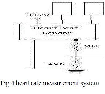
| Heart beat measuring system: Heart rate is a term used to describe the frequency of the cardiac cycle. It is considered one of the four vital signs this circuit is designed to measure the heart rate. The heart rate is measured by IR transmitter and receiver as shown in fig.4.When supply is ON the IR transmitter passes the rays to the receiver [5]. Depending on the blood flow, the IR rays are interrupted. Due to that IR receiver conduction is interrupted so variable pulse signals are generated, which are then conditioned and given to the controller unit where its count is calibrated and heart rate per minute is displayed in SCADA system. |
 |
 |
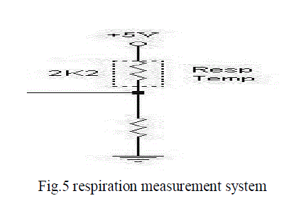 |
| Respiration measurement system: This circuit fig.5 is designed to measure the respiration temp. The thermistor is placed in a respiratory mask. Due to exhaled air temperature the resistance of the thermistor changes and according to which an output is induced which is an analog value. This value is given to the controller and variable value is displayed using SCADA system. The respiratory system facilitates oxygenation of the blood with a concomitant removal of carbon dioxide and other gaseous metabolic wastes from the circulation. |
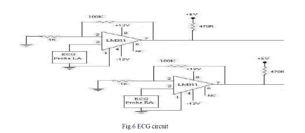
| ECG measuring system: An electrocardiogram is a graphic produced by an electrocardiograph, which records the electrical activity of the heart over time[2].The ECG signals (potentials obtained from the surface of the body) are sensed by the ECG electrodes and to given to the LM311(fig.6).where the operation is carried as follows. |
| A simplified model of the 311 is shown in fig.6 that its output behaves like a switch connected between output pin 7 and pin 1. Pin 7can be wired to any voltage V++ with magnitudes up to 40 V more positive than the –V supply terminal (pin 4). When (+) input pin 2 is more positive than (-) input pin 3, the 311’s equivalent output switch is open [8]. V0 is than determined by V++ and is +5 V.When the (+) input is less positive than (below) the (-) input, the 311’s equivalent output switch closes and extends the ground at pin 1 to output pin 7. Rf (feedback resistance of LM311) and Ri (input resistance of LM311) add about 50 mV of hysteresis to minimize noise effects so that pin 2 is essentially at 0 V. V0 (output voltage of LM311) is 0 V (switch closed) for positive half-cycles of Ei (input voltage to LM311). V0 is +5 V (switch open) for negative half-cycles of Ei. This is a typical interface circuit; that its, voltages may vary between levels of +15 V and -15 V, but V0 is restrained between +5 V and 0 V, which are typical digital signal levels, so the 311 can be used for converting analog voltage levels to digital voltage levels for interfacing applications[9] |
 |
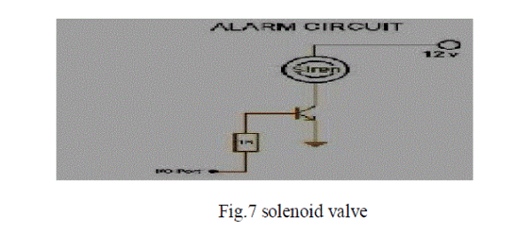
| Alarm circuit: The output of the controller decides buzzer operation. Whenever a patient body condition exceeds the normal condition then the alarm will be on. The buzzer works only if the Positive and the Ground is connected to the appropriate terminals shown in fig.7. We control the buzzer by controlling the ground signal given to the buzzer using a transistor. The operation is as follows. When the output of the controller is high, then the transistor conducts, allowing the low potential to reach one end of the buzzer, which results in sounding of the buzzer. When the output is Low, the transistor will not conduct. So ground is not applied to the buzzer. So the buzzer is not sounded. |
 |
PIC 16F877 MICROCONTROLLER
|
| PIC microcontroller is mainly used for the calibration of the bio-medical parameters mainly ECG signals, easy to configuring with PC or Laptop through MAX232, and also for ADC (analog to digital conversion) operation as shown in fig.8. The microcontroller that has been used for this paper is from PIC series [6].The main advantage of CMOS and RISC combination is low power consumption resulting in a very small chip size with a small pin count. The main advantage of CMOS is that it has immunity to noise than other fabrication techniques [7].Technology that is used in pic16F877 is flash technology, so that data is retained even when the power is switched off. Easy Programming and Erasing are other features of PIC 16F877. Mainly it has High-performance RISC CPU, Operating speed: DC - 20 MHz clock input,DC - 200 ns instruction cycle, Up to 8K x 14 words of Flash Program Memory, Up to 368 x 8 bytes of Data Memory (RAM). Up to 256 x 8 bytes of EEPROM data memory, Pin out compatible to the PIC16C73/74/76/77, Commercial and Industrial temperature ranges. |
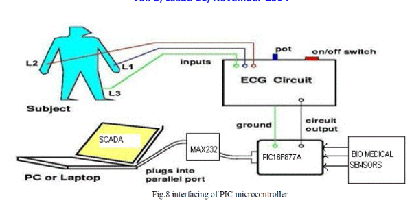 |
| MAX 232: this is mainly used to interfacing of PC with PIC microcontroller in order to maintain required TTL\ CMOS logic. The Max 232 is a dual RS-232 receiver / transmitter that meets all EIA RS232C specifications while using only a +5V power supply [1]. It has 2 onboard charge pump voltage converters which generate +10V and –10V power supplies from a single 5V power supply. It has four level translators, two of which are RS232 transmitters that convert TTL\ CMOS input levels into + 9V RS232 outputs. The other two level translators are RS232 receivers that convert RS232 inputs to 5V. |
SCADA USING VISUAL BASIC 6.0
|
| SCADA is the supervisory control and data acquisition system. SCADA also have its importance in medical system particularly in ICU.The status of patients is monitored using various sensors. The output of sensors is fed to either SCADA system or a microcontroller which complement each other in operation. The SCADA sends alarm signals to a technician will be supervising the entire ICU through the SCADA monitor. A properly designed SCADA system saves time and money by eliminating the need for service personnel to visit each site for inspection, data collection/logging or make adjustments [4]. |
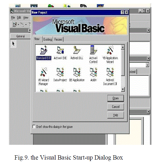
| The Visual Basic Environment: In this paper we are using VISUAL BASIC SCADA software. On start-up, Visual Basic 6.0 will display the following dialog box as shown in figure.9.You can choose to start a new project, open an existing project or select a list of recently opened programs[4]. A project is a collection of files that make up your application. There are various types of applications we could create; however, we shall concentrate on creating Standard EXE programs (EXE means executable program). Now, click on the Standard EXE icon to go into the actual VB programming environment. |
 |
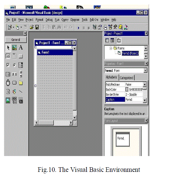 |
| Figure 10 shows the Visual Basic Environment, it mainly consists the following |
| A. The Blank Form window which you can design your application's interface. |
| B.The Project window displays the files that are created in your application. |
| C.The Properties window which displays the properties of various controls and objects that are created in your applications and it also includes a Toolbox that consists of all the controls essential for developing a VB Application. Controls are tools such as boxes, buttons, labels and other objects draw on a form to get input or display output. They also add visual appeal [10]. |
RESULT-SCADA SCREENS
|
| By using the visual basic environment we have to create the SCADA screens regarding our requirement as to display the desired the bio-medical parameters on the SCADA screens. |
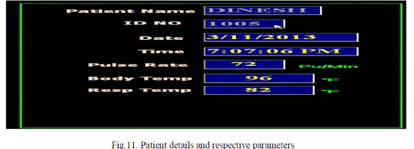
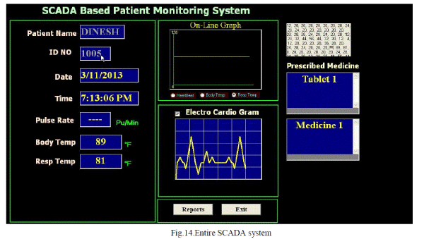
| Patient details and respective parameters: Using this VB 6.0 we have built a SCADA system for medical application i.e. the data from all the sensors is fed to the SCADA system. SCADA screen of Patient details is shown in Fig.11.In SCADA system using vb6.0 displays the patient details i.e., Name like Dinesh, id no:1005, date and time and patient respective parameters are displayed. |
 |
| VISUAL BASIC is a VISUAL and events driven Programming Language. These are the main divergence from the old BASIC. In BASIC, programming is done in a text-only environment and the program is executed sequentially. In VISUAL BASIC, programming is done in a graphical environment [4]. Because users may click on a certain object randomly, so each object has to be programmed independently to be able to response to those actions (events).Therefore, a VISUAL BASIC Program is made up of many subprograms, each has its own program codes, and each can be executed independently and at the same time each can be linked together in one way or another. Here, the gathering the data from the bio-medical sensors through data acquisitions. That data can be displayed on different display formats by using SCADA system. |
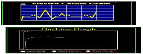
| Graphical analysis: The graphical analysis of each parameter can be done and monitored through SCADA system is shown in fig.12.This figure explains the graphical representation of the patient body condition parameters like electro cardio graph, heartbeat, body temperature and respiration rate. Here on-line graph represents the body temperature where x-axis represents time, Y-axis represents temperature. |
 |
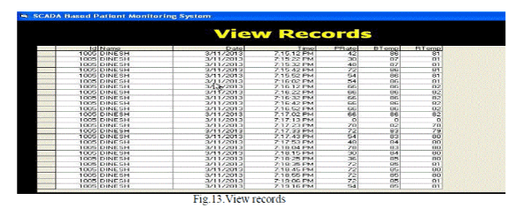
| Reports: Timely reports of the patient condition are generated which is very useful for the physician to take the future medical course regarding patient condition. Reports are shown in Fig.13.This fig describes the details of the patient health conditions at particular time and date here, we can collect the historical data of the patient body conditions also. These Screen is developed by VISUAL BASIC Programming Language. |
 |
| Entire SCADA system: This is the main SCADA screen of the project is shown in Fig.14. It includes Expert system, Patient details (Patient name, ID No, Date and Time), Parameter values(Pulse Rate, Body temperature and respiration rate) and Graphical analysis that describes the representation of parameters in the form of signal graph, here it represents the ECG(Electro cardio graph) signal and also heart rate, body temperature and respiration rate in the form of graph that is shown in the on-line graph. The Entire screen of Expert and SCADA Based Centralized Patient Monitoring and Escorting System is shown in fig.14.and from this screen we can continuously monitor the patient updated health conditions and mainly follows the expert guidance and prescribed medicine. |
 |
CONCLUSION AND FUTURE ENHANCEMENT
|
| Expert and SCADA based centralized patient monitoring and escorting system has been successfully constructed and designed and by using this paper, we can monitor the body temperature, respiration rate, heart rate and ECG of a patient successfully. Expert system protects the patient from serious conditions. Hence, we have seen the monitoring of some critical parameters through our SCADA based system, in a similar way other critical parameters can also be monitored by selecting reliable sensors and designing a proper SCADA system, the automated ICU monitoring can have many advantages and satisfy our needs. The system that is developed can be redesigned to be better if internet based system and android apps are upgraded and improved. |
| |
References
|
- Prabhat, P., Choudhury, S.R. ,Nemade, H.B. and Sahambi, J.S “Biomedical instrumentation based on electrooculogram (EOG) signal processing and application to a hospital alarm system”. Proceedings of International Conference on Intelligent Sensing and Information Processing. Publisher: IEEE, pages 535-540, Jan 2005.
- Cromwell Leslie and Weibell Fred J “Biomedical Instrumentation and Measurements”, 2nd Edition, PHI/Pearson. Pages 50-70
- http://www.ieee802.org
- Stuart A.Boyer , “SCADA: supervisory control and data acquisition”, ISA; 4th Revised edition (15 October 2009).
- J.H. Nagle, "Biopotential amplifiers", The Biomedical Engineering Handbook, Bronzino J.D. (Ed), Boca Raton (FL), CRC Press, pp. 1185 – 1195, 1995.
- John Iovine, “PIC Microcontroller Project Book: For PIC Basic and PIC Basic Pro Compliers”, McGraw-Hill Education, 29-Mar-2004.
- Fernando E. Valdes-Perez and Ramon Pallas-Areny. “Microcontrollers: Fundamentals and Applications with PIC” CRC Press, February 11, 2009.
- D Choudhury Roy and Shail Jain “Linear Integrated Circuits” New Age International,4thEdition.
- U.A.Bakshi and A.V.Bakshi“ Electrical Measurements and Instrumentation”, Technical Publications, 01-Jan-2009.
- SabeethaBegum.M and Kumarnath.J “LABVIEW Based Module For Bio Signals Monitoring”, IJCSMC, Vol. 3, Issue. 2, February 2014, pg.423–431.
- Sokullu, R, Akkas, M.A. and Çetin, H.E “Wireless Patient Monitoring System” The IEEE 2001 Fourth International Conference on Sensor Technologies and Applications (SENSORCOMM), pages 179 – 184,2010.
- Kamel, M Fawzy, S. and Kandil, A “Secure remote patient monitoring system” 1st Middle East Conference on Biomedical Engineering (MECBME) ), IEEE, pages 339 – 342, 21-24 Feb. 2011.
- S.L Toral, J.M. Quero, M.Elena, L.G.Franquelo, "A Microprocessor based system for ECG Telemedicine and Telecare". The 2001 IEEE International Symposium on Circuits and Systems, 2001.ISCAS 2001. vol. 4, Page(s):526-529, 6-9 May 2001.
- MohdFadlee A. Rasid and Bryan Woodward, "Bluetooth telemedicine processor for multichannel biomedical signal transmission via mobile cellular networks," IEEE Trans. inf. Tech in Biomedicine, vol .9, no.1, pp.35-43, 2005. (Pubitemid 40400333)
|