INTRODUCTION
|
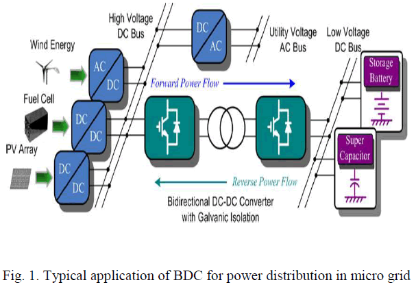
| The connection of our system to main grid is through isolator the required power is obtained from main grid by supplying losses and also facing discontinuity of power supply from the grid. This system utilizes a micro grid which is connected to various generating stations like wind fuel cell and PV array the output of wind energy is ac that is converted into dc fuel cell output is dc and PV output is dc all the sources outputs are connected to the high voltage dc bus and storage battery and super capacitor output voltage is connected to the low voltage dc bus and that is converted into ac stepping up the low voltage into high voltage that voltage converted into dc and given to the high voltage dc bus from that utility purpose that dc output voltage converted into ac given to the utility voltage ac bus. |
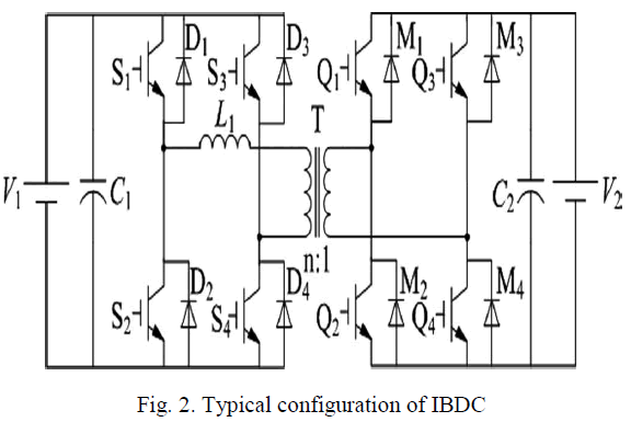
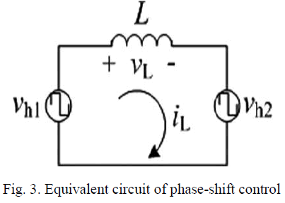
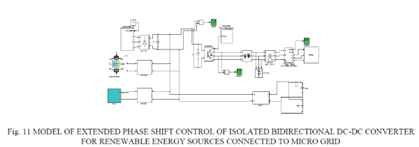
| In order to realize power distribution between energy generation systems and storage systems in micro grids, various bidirectional DC–DC converters have been proposed to interface between a high-voltage bus, where an energy generation system such as a fuel cell stack or a photovoltaic array is installed and a low-voltage bus, where usually an energy storage system such as a battery or a super capacitor is implemented galvanic isolation for BDC is required for flexibility of system reconfiguration and meeting safety standards an isolated bidirectional dc-dc is based on the single phase h-bridge topology with a high frequency isolated transformer compared to traditional dc-dc converter circuits this has many advantages such as electrical isolation high reliability easy to realize soft switching control and bidirectional energy flow In Traditional phase shift control H-bridges (H1 and H2 ) are switched in turn to generate phase-shifted transition square waves to the transformer’s primary and secondary sides. And the corresponding phase shift changes the voltage across the transformer’s leakage inductor to manipulate the power flow direction and magnitude. |
| This control method is attracting more and more attention due to its advantages such as small inertia, high dynamic performance, easy to realize soft-switching control, and so on. But in this method, the control of the power flow is dependent on transformer’s leakage inductor that result in great circulating power and current stress when the value of V1 /nV2 deviate far from 1, where n is turns’ ratio of the transformer. And then, the loss in power devices and magnetic components is increased and the efficiency of converter is reduced. |
 |
OPERATION PRINCIPLE OF EXTENDED-PHASE-SHIFT CONTROL
|
| A. Extended-Phase-Shift Control: |
| In order to significantly decrease the back flow power of the converter, vh1 should not be confined to square waveforms with 50% duty ratio. For example, if S1 and S4 do not have the same driving signal but have a phase-shift ratio of D1, as shown in Fig. 5, the transformer primary voltage will emerge as a three- level instead of the traditional two-level. Then the behaviors of iL will also be changed: the back flow appearance time (t = t0 ∼ t 0 and t = t2 ∼ t2) in Fig. 4 are divided into two intervals (t = t0∼t1, t = t1 ∼ t1 and t = t3∼t4, t = t4 ∼ t4) in Fig. 5, respectively. And the transformer primary voltage vh1 = 0, i.e., back flow power is 0, when t = t0∼t1 and t = t3∼t4. So the back flow power is decreased for a given transmission power. In the reverse power flow, we just need to exchange the operating states of the H-bridges H1 and H2. In Fig. 5, D1 is the phase-shift ratio between the driving signals of S1 and S4 or S 2 and S3 in H-bridge H1, we defined its inner phase-shift ratio, where 0≤D1 ≤1. D2 is the phase-shift ratio between the primary and secondary voltages of the isolation transformer, we defined its outer phase-shift ratio, where 0 ≤ D2 ≤ 1 and 0 ≤ D1+D2 ≤ 1. In fact, compared to the TPS control, there is not only the outer phase-shift ratio but also the inner phase-shift ratio in the proposed EPS control, which will decrease the current stress, expands regulating range of transmission power and enhances regulating flexibility. |
 |
 |
| There are three primary components of this research. First, a survey of Micro grids connected to the following techniques |
| 1. Wind generation |
| 2. Fuel cell |
| 3. PV array |
| 4. Super capacitor energy storage system (SCESS) |
| 5. Storage battery |
| Was conducted and have been categorized and are described. Second, the different architectures identified during the survey are analyzed for the level of energy security provided at a given cost. Finally, key parameters are identified that significantly influence the optimal selection of micro grid architecture suitable to that particular terrain. |
SIMULATION RESULTS AND DISCUSSION
|
| All the 5 DC sources are modelled and simulated in the proposed model. The individual models are specified below. |
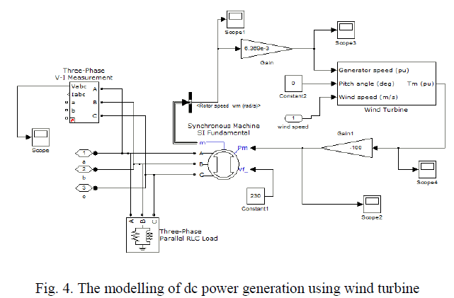
| A. WIND MODEL: |
| The modelling of dc power generation using wind turbine is considered here. The model is stipulated below. |
 |
| Although stand alone windâÃâ¬ÃÂbattery or wind diesel systems do exist, the majority of wind turbines is erected in countries with an extended electricity grid and these are hence connected to this grid. The grid connection of solitary wind turbines is relatively straightforward Voltage at the turbine’s terminals is normally lower than the voltage of the grid to which it is connected, leading to the need for a transformer. Further, switchgear is necessary to disconnect the wind turbine in case of a short circuit or in order to prevent what is called islanding, a situation in which a small part of the grid continues to operate with a local balance between generation and load, but without being connected to the main system. When large numbers of wind turbines are |
| Connected to a system and they replace a substantial fraction of the output of the conventional synchronous generators, they will start to affect various aspects of the system behavior. This will particularly be the case during periods with low loads and high wind speeds, because in these situations the relative contribution of wind power is at its maximum As long as the power generated by the power plants can be controlled, this is not a principal problem, although the dispatch of the generating capacity, i.e. determining which power plants should be operated to supply the load most effectively and efficiently while taking into account fuel prices and the technical characteristics of the plant inventory, is not straightforward at all. However, a significant contribution of generators whose output is not controlled, such as the present wind turbines, poses a principal problem given today’s system balancing practices, because such generators cannot contribute to maintaining the system balance |
| B. FUEL CELL MODEL: |
| The fuel cell model used here is a direct tool from mat lab library of 2012a version. |
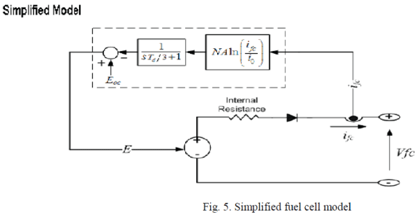 |
| The simplified model represents a particular fuel cell stack operating at nominal conditions of temperature and pressure. The parameters of the equivalent circuit can be modified based on the polarization curve obtained from the manufacturer datasheet. You just have to input in the mask the value of the voltage at 0 and 1 A, the nominal and the maximum operating points, for the parameters to be calculated. A diode is used to prevent the flow of negative current into the stack. |
| Model Assumptions: |
| • The gases are ideal |
| • The stack is fed with hydrogen and air |
| • The stack is equipped with a cooling system which maintains the temperature at the cathode and anode exits stable and equal to the stack temperature |
| • The stack is equipped with a water management system to maintain the humidity inside the cell at appropriate level at any load |
| • The cell voltage drops are due to reaction kinetics and charge transport as most fuel cells do not operate in the mass transport region |
| • Pressure drops across flow channels are negligible |
| • The cell resistance is constant at any condition of operation |
| C. PV ARRAY: |
| The P-V array model is built and simulated as below |
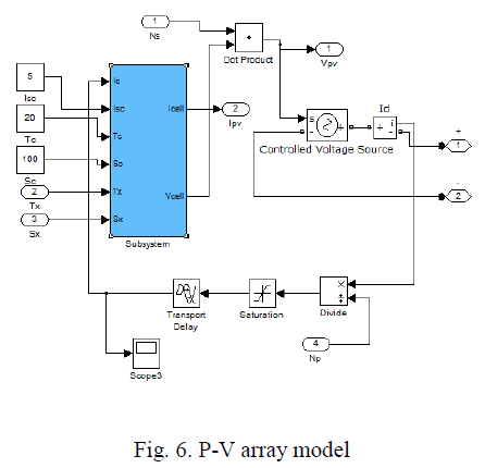 |
| A general block diagram of the PVA model for GUI environment of Simulink is given along with filter and load models. The block called PVA model for GUI is the last stage of the model. This block contains the sub models that are connected to build the final model. A diode (D1) isconnected in series with the load circuit to prevent the reverse current flow. A filter is connected before the load to maintain a stable voltage. The filter contains a series R-L and parallel C elements. The PVA consists of 8 PV cells all connected in series to have a desired voltage output. Depending on the load power required, the number of parallel branches can be increased to 2 or more. The effects of the temperature and solar irradiation levels are represented by two variables gains. They can be changed by dragging the slider gain adjustments of these blocks named as variable temperature and variable solar irradiation. Since the main objective is the development of the PVA functional model for the Simulink environment, the other parts of the operational block diagram given in Fig.are not going to be explained in full detail. However, just to describe the main diagram, as it can readily be seen, the system is modeled to supply power to both dc and ac loads. The dc load is directly coupled while the ac load is fed through a three-phase inverter and an isolation transformer with a turn ratio 1. |
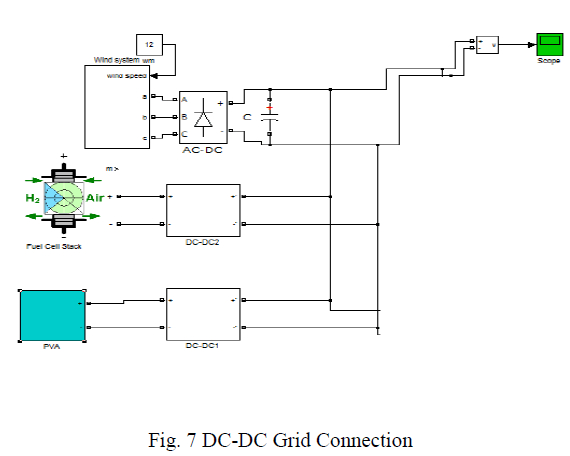
DC-DC GRID CONNECTION:
|
 |
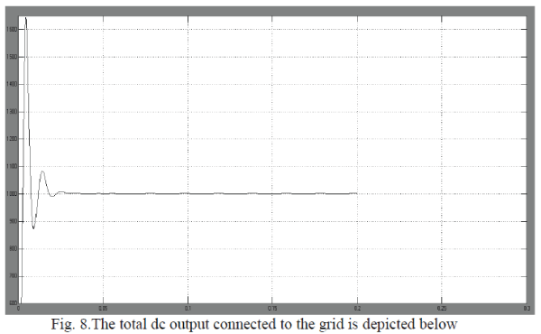 |
DC-AC CONVERSION USING 3-PHASE INVERTER:
|
| The dc grid output is then connected to a dc- ac converting 3 Phase Inverter. The input of the inverter is 850 volts dc supply. The output AC supply is 850 volts L-L RMS. |
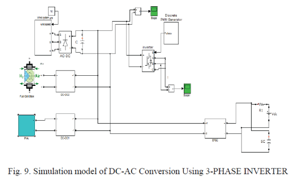 |
| The Universal Bridge block implements a universal three-phase power converter that consists of up to six power switches connected in a bridge configuration. The Universal Bridge block allows simulation of converters using both naturally commutated (line-commutated) power electronic devices (diodes or thyristors) and forced-commutated devices (GTO, IGBT, and MOSFET). The Universal Bridge block is the basic block for building two-level voltage-sourced converters |
| The device numbering is different if the power electronic devices are naturally commutated or forced-commutated. For a naturally commutated three-phase converter (diode and thyristor), numbering follows the natural order of commutation: |
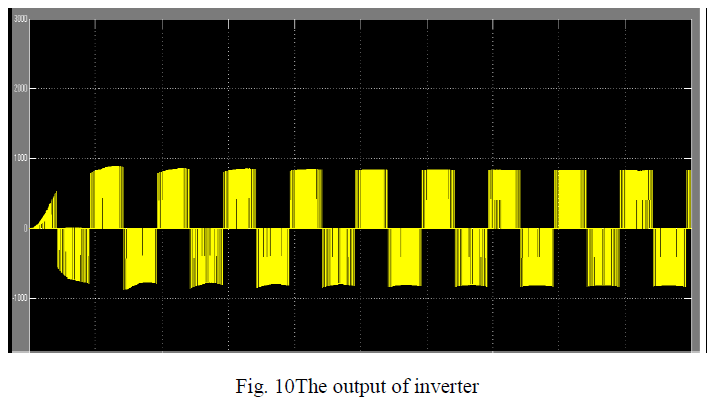
| The output of inverter is shown in below figure |
 |
GRID CONNECTION
|
| The five cases for dc power generation are analyzed for their representative locations and converted into 3 Phase AC supply using inverter. The output of inverter is in turn connected to the main AC grid to supply the ac power for remote locations using distributed transmission network. |
 |
CONCLUSION
|
| The results of this analysis show that the most cost-effective micro grid solutions will be those that take into account the needs of the local commercial electric grid and implement their systems so that they can earn value helping to meet those needs. In areas where commercial generation sources are stretched thin or with significant congestion on the electric grid, local generation can play an important role. A number of DoD installations enlist their backup generation resources in emergency demand-response programs, which aim to alleviate short-term congestion problems in the commercial transmission infrastructure. In these programs the installation is given a periodic credit on their electricity bill for promising to reduce the installation’s demand, either through load shedding or by turning on backup generators, when provided with a signal by the local utility. Analysis shows, and several installations have confirmed, that the financial savings from these demand-response programs more than pay for the cost of generation assets |
References
|
- F. Blaabjerg and Z. Chen, “Power electronics as an enabling technology for renewable energy integration,” J. Power Electron., vol. 3, no. 2, pp. 81–89, Apr. 2003.
- L. Y. Pao and K. E. Johnson, “A Tutorial on the Dynamics and Control of Wind Turbines and Wind Farms,” Proc. Amer. C trl. Conf., June 2009.
- National Energy Technology Laboratory, “Fuel Cell Handbook”, 6th edition, Morgantown, WV, 2002.
- Boccaletti C., Di Grazia G., Fabbri G., Nisticò E., “Energy models for stand alone power systems”, EETI – 5th International Congress on Energy, Environment and Technological Innvovation, Rio de Janeiro, Brazil, 2004.
- W. Xiao, W. G. Dunford, and A. Capel, “A novel modeling method for photovoltaic cells,” in Proc. IEEE 35th Annu. Power Electron. Spec. Conf. (PESC), 2004, vol. 3, pp. 1950–1956.
- GwinyaiDzimano, B.S. “Modeling of Photovoltaic Systems”, The Ohio State University, Pg.1-18,48-52, 2008.
- R. E. Gerver, 3D Thermal-Electrochemical Lithium-ion Battery Computational Modeling, Masters Thesis, The University of Texas at Austin, Austin, TX, (2009).
- J. S. Newman and K. E. Thomas-Alyea, Electrochemical Systems, Wiley- Interscience, Hoboken, N.J. (2004).
- N. S. Zhai, Y. Y. Yao, D. L. Zhang, and D. G. Xu, "Design and Optimization for a Supercapacitor application System", International Conference on Power System Technology, 2006.
- P. Srithorn, M. Sumner, and L. Yao, R. Parashar, "A STATCOM with supercapacitors for enhanced power system stability" 4th IET Conference on Power Electronics, Machines and Drives , 2008 , pp.96-100.
|