Keywords
|
| Contactless slipring systems, IPT (Inductive Power Transfer), Magnetic shielding, Rotary applications |
INTRODUCTION
|
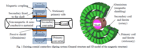
| Inductive Power Transfer (IPT) technology offers a good solution of transferring powerto electrical loadswith relative movement to the stationary power source[1, 2]. This new technology has been used in different applications; each has particular specifications and restrictions. A range of applications such as in Electrical Vehicle (EV) [3], biomedical implants [4], robotics[5], etc. have been presented and several approaches have been proposed based on the individual requirements. Apart from linear movement, one particular scenario is to transfer power to rotatory loads. Currently this is achievedusing mechanical slipring assemblies utilizing conductive carbon brushes sliding on conductive rotating rings. Use of conventional slipring assemblies based on direct mechanical contacts is often undesirable. Their inherent high friction characteristics due to the contact between the brushes and moving conductors often cause high wear and tear, so frequent maintenance or even full replacement is required which can significantly increase the operational costs in applications such as in wind turbine applications [6, 7]. To eliminate the direct mechanical contacts, acontactless slipring with coaxial magnetic coupling shown in Fig. 1 has been developed by PowerByProxi Ltd and currently installed as a trial for a wind turbine pitch control[8, 9]. However, in this design the primary side encircles the secondary side fully, which results in a system with a fixed air gap and asymmetrical primary and secondary. In such a design, in addition to individual design procedures for each side, any changes in the air gap require a complete system redesign, which can be time consuming and costly. Moreover, if there is a barrier wall along the system shaft, the coaxial structure would not work. |
 |
| This paper proposes a new through-hole type contactless slipring with identical primary and secondary magnetic structures. The face to face configuration of the proposed system allows for flexible air-gaps, and can work even when a barrier wall is located between the primary and secondary sides. |
THE PROPOSED SYSTEM
|
| Fig. 2 shows the proposed face to face contactless slipring system. It consists of two identical stationary and rotatable parts which are electrically isolated by an air gap and magnetically coupled. Therefore, the secondary can be movable (linearly or/and rotating) giving flexibility, mobility and safeness for the supplied loads. This is one of the advantages of the proposed system that accomodates the possiblity of linear and rotary movement for the secondary as compared to the existing coaxial contactless slipring. Moreover, its face to face feature provides the possibility of using such a design with a primary located outside and a secondary in the other side of a barrier wall. However, this is possible if the barrier wall is made of a non-magnetic and non-conductive material. |
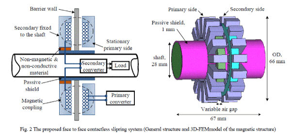 |
| The primary converter employed in the primary side produces a high frequency alternating current flows through an external coil (primary), generating an alternating electromagnetic field. In fact, high frequency power converter improves the power transfer characteristics by fast changing rate of magnetic field. For the proposed system, a currentfed push-pull converter with Zero Voltage Zwitching (ZVS) operation is used to drive the primary coil at a constant primary current. The presence of the time varying field within the secondary coil induces currents which can be converted to power and supplied to the load. Due to the mutual magnetic coupling between the primary and the secondary coils, an inductive electromotive force is induced in the secondary coil which forms a voltage source for the secondary power supply. Since the magnetic coupling between the two coils is low as compared to the tightly coupled transformer, the induced voltage in the secondary coil is usually inappropriate to be fed directly to the connected load. The secondary converter then realizes rectifying and power converting according to the load requirements. |
EQUIVALENT CIRCUIT AND POWER TRANSFER CAPABILITY ANALYSIS
|
| In this section an electrical model of a contactless slipring is presented to offer an improved analysis of the magnetic structure performance, simulation, derivation of mathematical equations to put a figure on each aspect of a magnetic component. In the case of IPT systems even though the power transfer occurs in a similar way as that of conventional transformer, there are various reasons that make it difficult to model the system using the conventional equivalent circuit[10]. Instead the interactions between the primary and the secondary coils are described using a mutual inductance model as shown in Fig. 3. As it can be seen a secondary coil of inductance L2 mutually coupled to a primary coil carrying current I1 through a mutual inductance M [11]. Note that winding losses are not considered in the presented model. Moreover, the air gap in the path of the magnetic flux leads to low flux density which tends to make the core loss very small, so the core loss component also may be neglected without significant loss of accuracy. |
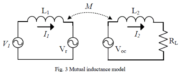 |
| The two fundamental parameters of a contactless slipring system as an IPT system are the open circuit voltage Voc (obtained when RL = ∞) and short circuit current Isc (obtained when RL = 0) are given as, |
 |
 |
| The mutual inductance M is a function of the geometry of the magnetic structure and it can be found by simulation, measurements or modeling the physical structure [12]. In the model of Fig. 3, the reflected voltage Vr represents the total effect of the secondary on the primary side and determined by the current flowing within the secondary coil and the mutual inductance M as given by, |
 |
| To achieve this requirement, the effect of the secondary can be represented by the equivalent reflected impedance as following, |
 |
| The short-circuit current on the other hand, is defined by the input impedance seen by the open circuit voltage Voc to be Z2 as, |
 |
| Combining (4) and (5), the equivalent reflected impedance of the secondary back onto the primary is expressed as, |
 |
| where Z2 is the secondary impedance given by, |
 |
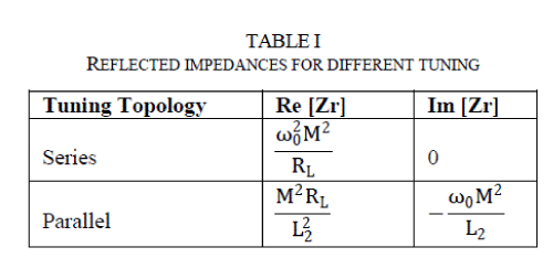
| Since the secondary power pickup circuit depends on the selected compensation topology, the reflected resistance and reactance at the resonant frequency onto the primary side is different for series and parallel-tuned secondary coil as given in Table I[13].It can be seen from Table I that the reflected impedance for the series-tuned secondary coil is pure resistive, while the parallel-tuned secondary coil reflects capacitive component too. This is one of the major differences between the series and parallel compensated secondary coils. The reflected impedance can then be compared and combined with the impedance of the primary coil. The power transferred from the primary to the secondary is simply the reflected resistance (real part of the reflected impedance) multiplied by the squared primary current as given by, |
 |
| Note that the power transferred to the secondary side can also be calculated based on the obtained un-compensated power (as a product of Voc and Isc) as following [3], |
 |
| where Qs is the secondary power pickup circuit quality factor and is different depending on the secondary tuning topology as given by, |
 |
| Although the higher the Qs, the higher the power transfer; however for some reasons maximum practical achievable Qs is about 10 [14]. |
 |
3D-FEM SIMULATION AND ANALYSIS
|
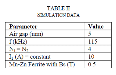
| A 3D finite element modelis developed to study the magnetic behavior of the proposed slipring system using JMAG package as shown in Fig. 2b. Table II demonstrates the assigned simulation data.Normally in contactless slipring systems an aluminium shield is used to protect the shaft from the stray flux lines. The stray flux lines which are passing through the shaft induce eddy currents and as a result generate heat in the shaft [15-17]. Aluminium shield however creates power losses and usually a trade-off design. Thus a good compromise between power losses and shaft protection has to be taken in consideration during design. In this paper a method of magnetic shield is proposed using a soft flexible ferrite material FFSX. Note that the flexible ferrite material proposed for shielding is available in the market and practically used for experimentations as presented later in section-V [15]. Therefore, to investigate the impact of the existing magnetic shielding method and the proposed method, the simulation study is performed for different conditions as shown in Table III. |
 |
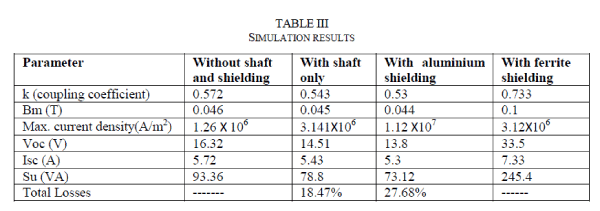 |
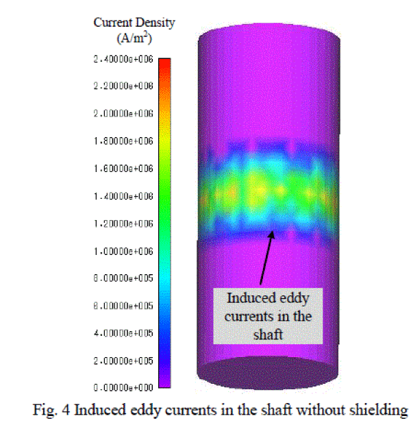
| At first the system is simulated without any shaft as well as any magnetic shielding used. The un-compensated power as a product of Voc and Isc is reached about 93.36 VA. When a steel shaft is added to the system, the power decreased to 78.8 VA. This is because about 18.47 % power lost within the shaft due to the induced eddy currents. Fig. 4 shows the simulated current density due to the induced eddy current in the shaft. Maximum current density is reached about 2.4X10⁶ within the shaft which is a considerable value as compared to the maximum system current density about 3.141X10⁶ and most likely creates substantial heat in the shaft.Next, an aluminium sleeve added to the system over the steel shaft. From Fig. 5a the current density of the induced eddy currents in the shaft is greatly reduced to 6.5X10⁴. However the maximum current density simulated for the system is about 1.12X10⁷and it is within the aluminium shield (see Fig. 5b). The power decreased even more about 9.21 % (27.68 - 18.47) by adding aluminium shield. |
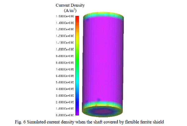
| When ferrite material used for magnetic shielding, the power increased about 3.11 times from 78.8 VA (with shaft only) to 245.4 VA. Using ferrite in fact provides a magnetic path with low reluctance for the flux lines and almost shorting one of the air gaps between the two sides. This would enhance the magnetic coupling structure and results in an increased mutual inductance and consequently greater transfer impedance (see Eqn.6). A system with high transfer impedance is able to transfer more power to the secondary side as stated in (8).As it can be seen from Fig. 6, using a ferrite shield totally covers the shaft from the fringing magnetic fields due to the air gap adjacent to the shaft. However there are some eddy currents with 1.5X10⁶ current density induced at the ends of the shaft which can be mitigated by extending the ferrite shield. In order to estimate the power losses within the shaft for this case, the shaft is removed and the simulation is repeated with only a ferrite shield. The power is reached about 248 VA (33.76 V * 7.35A) which means that only about 1.06 % power is lost in the shaft with ferrite shielding. This amount of power is negligible and less likely of causing damage to the system. Maximum flux density is simulated for the case with ferrite shielding about 0.1T which is still much lower than the saturation limit of the used ferrite with 0.5T. This indicates that the system can still be driven for higher power levels without saturation problem. |
 |
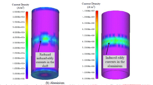 |
| Fig. 5 Simulated current density when the shaft covered by an aluminium |
 |
PRACTICAL RESULTS
|
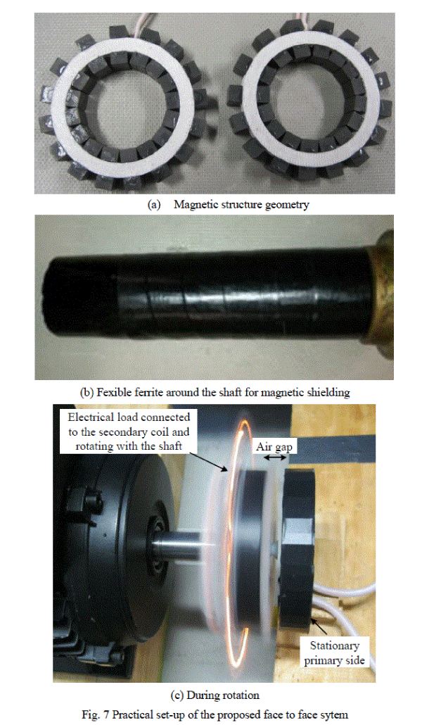
| Besides the theoretical and FEM analysis, a practical model of the proposed system is constructed for further system evaluation as shown in Fig. 7. The practical dimensions and operating conditions are similar to the developed FEM model to have a reasonable comparison between both results. As it can be seen, a set of U-shape of ferrite cores are used to create a complete ring of ferrite around the shaft. The primary and the secondary are identical and they are throughhole type which they can be designed for any shaft’s diameter. At first, the system is tested when the shaft is standstill, and then the shaft together with the electrical load mounted on it is driven by an electrical motor to a speed up to 1400 rpm in order to investigate the effect of the rotation on the system’s performance. It was observed that the system parameters at the primary side remain unchanged, meaning the rotation does not affect the performance of the system. This was also verified during the inductance measurements. It was found that the mutual inductance between the two sides is constant regardless of the positioning and rotation of the secondary side. |
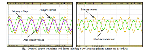
| Table IV shows the practical results of the open circuit voltage and short-circuit current for various cases similar to the simulation. The open-circuit voltage and short-circuit current waveforms taken from the experiment for the case with ferrite shielding are good sinusoidal as shown in Fig. 8 at 115 kHz. The open-circuit voltage measured for the case with ferrite shielding about 36.85 V and the 6.48 A short-circuit current. These values give about (36.85 * 6.48 = 236.83) VA un-compensated power. It has been shown in [14] that maximum power that can be transferred to the load is about half of the un-compensated power (≈ 0.5 Su). If the required power is greater than this value, then it is essential to tune the secondary inductance. In case of the practical model of the proposed system, the used Litz wire (AWG12) can handle maximum current about 10.8 A @40Ãâ¹ÃÅ¡C; thus for a fully series-tuning case, the short-circuit current of the system can be increased from 6.48A to 10A by Qs (≈ 1.55). Since the secondary inductance (Lp= Ls= 4.5 μH) and the frequency are known parameters for the system, the quality factor then is determined by the connected load as stated in (10). Thus, about 2.01Ω resistive load is connected to the series-tuned secondary side. According to (9), about (1.55*236.83 = 367 Watts) output power is measured at the load side. |
 |
 |
 |
| Referring to Table III and Table IV; it can be seen that there is a very good agreement between the FEM and the experimental results for the air gap (= 5 mm). This signifies the accuracy and feasibility of the proposed system. The power density of such a system with the dimensions mentioned in Fig. 2b is fairly superior in practice and it can be used in important power applications as detailed in the next section. |
SUITABLE APPLICATIONS
|
| A. Wind turbine pitch control system |
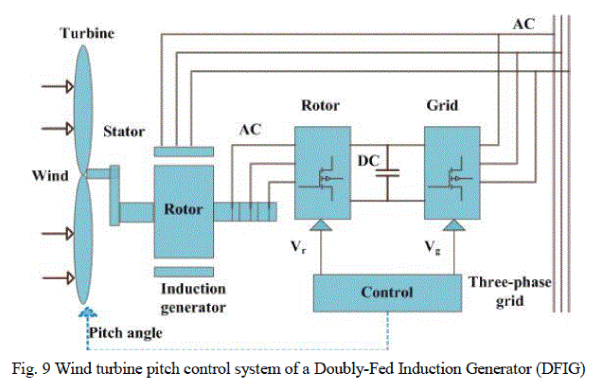
| An important application of the proposed system is in wind turbine pitch control applications. This control system is mounted on the rotating shaft of the turbine and is used to control the blade angle in accordance to the speed of wind. A wind turbine pitch control system is shown in Fig. 9. Generally, power is transferred to this system via conventional slipring systems. As discussed earlier, the operational cost would be very high in case of need for cleaning or brush replacement. Therefore, replacing the conventional slipring system with a contactless method would be very advantageous for wind turbine applications. |
 |
| B. Power generation excitation systems |
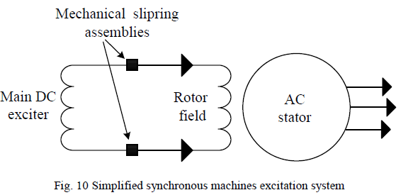
| An IPT-basedcontactless slipring can be used in other applications, such as synchronous machines excitation systems transferring power to the rotor winding (see Fig. 10). Using such a system for excitation systems has great advantages as compare to the currently used solutions. To begin with, it eliminates the direct contact and frequent maintenance of the brush-system. On the other hand, it is capable of transferring power to the standstill shaft with a faster response as compare to the rotating-diodes system[9]. |
 |
| C. Robotic joint applications |
| Transferring power across a robot joint by the means of mechanical sliprings and flexible cables is undesirable. Contactless slipringsoffer a very good solution to eliminatedirect mechanical contacts or cable twisting to achieve 360 degrees freedom of rotation [18, 19]. The proposed system is particularly good for robotic joints with fixture walls/barriers along the shaft for mechanical supports. |
| D. Radar applications |
| One of the other important applications of the proposed contactless slipring system is to transfer electrical power from the static frame to an airborne frame of radar. The same as other presented applications, usually power transfer is achieved by the use of slipring assemblies [20, 21]. If this can be achieved wirelessly using a contactless slipring system, it would have great benefits of removing physical contacts between the stationary and revolving parts and minimizing the maintenance. |
CONCLUSIONS
|
| This paper has presented a new face to face design of contactless slipring system for wireless power transfer in rotary applications. It has shown that as compared to the existing coaxial contactless slipring, the face to face type is much simpler to cope with air gap variations. Moreover, it can be potentially used in situations with barrier walls between the stationary and the rotating sides. A practical system has been build and tested with a series tuned power pickup with a quality factor (QS) of 1.55 and output power of 367 Watts to verify the proposed method. It has been found that using flexible ferrite material for shielding in addition to protecting the shaft from stray magnetic field increases the power transfer capability of the system to about 3 times. |
References
|
- M. P. Kazmierkowski and A. J. Moradewicz, "Unplugged But Connected: Review of Contactless Energy Transfer Systems", in Industrial Electronics Magazine, IEEE, vol. 6, pp. 47-55, 2012.
- A. P. Hu,Liu and Li, HL., "A Novel Contactless Battery Charging System for Soccer Playing Robot", in Mechatronics and Machine Vision in Practice, M2VIP, 15th International Conference on, pp. 646-650, 2008.
- S. Raabe and G. A. Covic, "Practical Design Considerations for Contactless Power Transfer Quadrature Pick-Ups", in Industrial Electronics, IEEE Transactions on, vol. 60, pp. 400-409, 2013.
- W. Yanzhen, Hu, A. P., Budgett D. ,Malpas, S. C. and Dissanayake, T.., "Efficient Power-Transfer Capability Analysis of the TET System Using the Equivalent Small Parameter Method", Biomedical Circuits and Systems, IEEE Transactions on, vol. 5, pp. 272-282, 2011.
- L. J. Chen, Tong, WengIp Simon, Meyer, Bernd, Abdolkhani, Ali and Hu, Aiguo Patrick "A contactless charging platform for swarm robots", in IECON 2011-37th Annual Conference on IEEE Industrial Electronics Society, pp. 4088-4093, 2011.
- C. Holzapfel, "Wear and electrical properties of slip rings", in Electrical Contacts (ICEC 2012), 26th International Conference on, pp. 86-90, 2012.
- G. Gao and W. Chen, "Design challenges of wind turbine generators", in Electrical Insulation Conference, EIC, IEEE, pp. 146-152, 2009.
- K. Bhargava,LeicasJr, Eugenio Sia, Mishriki, Fady, Ren, Saining Sunny, Robertson, Daniel and Walton, Robert, "A contactless power transfer system," ed: WO Patent App. PCT/NZ2011/000,199, 2011.
- D.-H. Kang, Koo, Dae-Hyun, Vadan, Ion and Curiac, Paul, "Contactless Excitation System for Synchronous Generators", in ICREPQ, International Conference on Renewable Energy andPower Quality, 2005.
- A. Abdolkhani and A. P. Hu, "A contactless slipring system by means of axially travelling magnetic field," in Energy Conversion Congress and Exposition (ECCE), IEEE, pp. 1796-1803, 2012.
- J. Acero, Carretero, C., Lope, I., Alonso, R., Lucia, O. and Burdio, J. M., "Analysis of the Mutual Inductance of Planar-Lumped Inductive Power Transfer Systems" in Industrial Electronics, IEEE Transactions on, vol. 60, pp. 410-420, 2013.
- A. Abdolkhani, A. P. Hu and N. C. K. Nair, "Modelling and Parameters Identification of Through-Hole Type Wind Turbine Contactless Sliprings," SCIRP/ Engineering, vol. 4, pp. 272-283, 2012.
- C. S. Wang, Stielau, O.H. and Covic, G.A., "Design considerations for a contactless electric vehicle battery charger" in Industrial Electronics, IEEE Transactions on, vol. 52, pp. 1308-1314, 2005.
- O. Stielau and G. Covic, "Design of loosely coupled inductive power transfer systems," IEEE, Power System Technology, pp. 85-90, 2002.
- Availble on: http://intermark-usa.com/.
- A. Abdolkhani and A. Hu, "A Sandwiched Magnetic Coupling Structure for Contactless Slipring Applications" in International Geoinformatics Research and Development, vol. 2, Issue 3, September 2011.
- A. Abdolkhani and A. P. Hu, "A Novel Detached Magnetic Coupling Structure for Contactless Power Transfer" in IECON 2011-37th Annual Conference on IEEE Industrial Electronics Society, pp. 1103 - 1108, Nov 2011.
- K. D. Papastergiou and D. E. Macpherson, "Air-gap effects in inductive energy transfer" in Power Electronics Specialists Conference, PESC, IEEE, pp. 4092-4097, 2008.
- Y. Hattori, Kuroki, Yoshihiro, Ishida, Tatsuzo and Yamaguchi, Junichi, "Robot and joint device for the same," ed: Google Patents, 2005.
- Y. Hattori, Kuroki, Yoshihiro, Ishida, Tatsuzo and Yamaguchi, Junichi, "Leg-movement-type robot and its hip joint device," ed: EP Patent 1,083,120, 2005.
- W. Xiao and L. Chao, "Reliability Design and Test of One Spaceborne Slip Ring" in Electro-Mechanical Engineering, vol. 5, p. 008, 2009.
- L. Chao, "Protection of Power Slip-ring in Radar System" in Electro-Mechanical Engineering, vol. 5, p. 012, 2007.
|