The continuation of an active call or service is one of the vital metrics for assessing the performance of a wireless communication system. The handover process is inevitable when the Mobile node is roaming across the networks. When a mobile node is moving from home access point to another access point, handover with low latency and minimum packet loss is required in order to get better Quality of Service (QoS) for IP applications such as Voice over IP (VoIP), video conferencing, live streaming in mobiles etc. In this paper, Modified Reactive Fast Handover for Mobile IPv6 is used to reduce handover latency and packet loss, which involves packet buffering at the Correspondent Node (CN). Network Simulator version 2 (NS-2) is used under ubuntu operating system as simulation tool for the proposed scheme.
Keywords |
| Packet Loss, Handover latency, Mobile IPv6, QoS, NS-2 |
INTRODUCTION |
| Mobility is an important attribute of a mobile communication system. With the advent of latest technologies in wireless
communication, the user is facilitated with the ubiquitous internet access when the user is roaming across the network.
Handover plays an anchor role in mobile communication for the fulfillment of communication between two parties.
For any communication system, the QoS is the deciding factor for the performance evaluation of the system. Packet
losses are the main threat to the QoS of a communication system. In the handover situation the packet losses and the
handover latency should be considered in order to get better results and uninterrupted access to the communication. So,
the QoS of the communication system depends on both handover latency and packet loss. |
| The handover latency is the amount of time taken by the Mobile node to switch its point of attachment from home
access point to another access point. It can be considered as the time required for movement detection, IP protocol
operations, for performing handover. |
| Next Generation Networks (NGN) are using in this modern era in which the data is transferred in packets or chunks.
The packets carry information. The packet loss is regarded as one or more packets fails to reach the destination. The
general reasons for packet loss are insufficient Bandwidth, hardware problems, routing failures etc. |
LITERATURE SURVEY |
| Yvette E. Gelogo et al. [1] proposed a Reducing packet loss for Mobile IPv6 Fast Handover (FMIPv6). In this, the
researchers are keen on reducing the packet losses and proposed their method to improve the packet loss by using proper
buffering at the routers in predictive and reactive FMIPv6 models. They also insisted that the buffer size should be used
based on the data transferred. If the data is like voice over IP, it needs small buffer size compared to high-resolution
streaming video as the latter has larger packet sizes and high arriving data rates. |
| Salim M. Zaki et al. [2] proposed a Mitigating packet loss in Mobile IPv6 using two-tier buffer scheme. In this the
authors proposed a way to reduce the packet loss for Mobile IPv6 handover. This process involves deploying a buffer at
the CN side to retrieve the forwarded traffic from CN. The buffered packets will be sent to the Mobile Node (MN) immediately after the receiving of the Binding Update (BU) message from MN and then handed over to other access
point. |
| Rajeev koodli proposed a fast handover for Mobile IPv6 in RFC et al. [3]. In this he listed two types of fast handovers
namely predictive and reactive fast handovers for MIPv6. In this he said that the handover latency is the outcome of the
link switching delay and IP protocol operations and also stated that the mobile node is incapable of receiving the traffic
intended for it from the correspondent node during this handover latency. |
BACKGROUND |
| At present, the used communication protocol is IP or IPv4, which suffers from triangular routing problem. IPv4 has less
address space (32-bit) and has high packet transmission delays compared to the next generation IP or IPv6. IPv6
comprises of 128-bit address space and it overcomes the problem of triangular routing by route optimisation technique
which results in less packet delays. Mobile IPv6 is to facilitate the uninterrupted internet services to the Mobile users
when they roam across the network. There are various mobility management protocols of Mobile IPv6 developed by
IETE. The IETE standardised protocols Mobile IPv6 (MIPv6), Fast Handovers for Mobile IPv6 (Predictive FMIPv6
and Reactive FMIPv6), Hierarchical Mobile IPv6 (HMIPv6), and Proxy Mobile IPv6 (PMIPv6), out of which some are
host based and some are network based. |
| Among the above mentioned protocols, the Reactive FMIPv6 produces best results in terms of handover latency. It
results approximately 5.5msec handover latency, which is the lowest of all the mobility management protocols. Now
take a glance about the operation of the reactive FMIPv6. |
Operation of reactive Fast Handover for Mobile IPv6: |
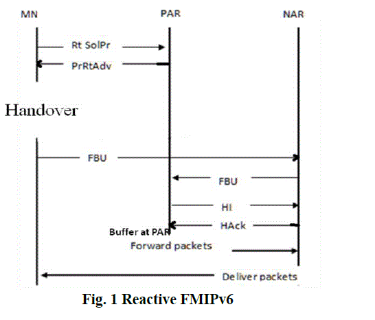
| The signal flow graph of reactive FMIPv6 is illustrated in fig 1. |
 |
| The messages illustrated in the above figure are described below. |
| Router Solicitation for Proxy (RtSolPr): The Router Solicitation for Proxy message is sent by the MN to the Previous
Access Router (PAR), when the handover of MN is imminent. It is the message asking the PAR to perform router
discovery process in order to find the available access routers information. |
| Proxy Router Advertisement (PrRtAdv): The Proxy Router Advertisement message is sent by the PAR to the MN in
response to RtSolPr. It provides the list of access routes available for the MN in the foreign network. |
| Fast Binding Update (FBU): The Fast Binding Update message is sent by the MN to the Next Access Router (NAR)
and in turn the NAR is forward this message to the PAR |
| Handover Initiate (HI): The Handover Initiate message is sent by the PAR to the NAR to authenticate the New Care of
Address (NCoA) quoted in FBU message. |
| Handover Acknowledgment (HAck): Handover Acknowledgment message is sent by the NAR to the PAR in response
to the HI message to validate NCoA. |
| For the above operations, PAR holds the incoming packets in order to reduce packet loss. After the confirmation of the
NCoA of MN in the foreign network, the buffered packets are forwarded to the MN through NAR. This process is called
Tunneling. Thus ends the handover process. Then the packets are transmitted to MN through NAR. |
| Handover latency, it is quite less for reactive FMIPv6 when compared to the classical MIPv6 protocol as the anticipation
of the MN towards the NAR before it is handed over to the other network. When comparing the handover latency
between predictive and reactive fast handovers, the reactive handover results slightly less to that of predictive one. |
| Packet loss, the deciding factor to evaluate the performance of handover, there are measures have taken to reduce the
packet loss in this Fast Handovers. The packet losses are reduced by taking the buffer at the routers. In the predictive
FMIPv6, a buffer is deployed at the NAR to withstand packet losses. In the reactive FMIPv6, buffer is placed at the PAR
to store the lost packets during the handover time as in that duration the MN is unable to receive or send packets. |
PROPOSED METHOD |
| Now let us look at the spaces of improvements in reactive FMIPv6. |
| The packets are stored in the buffer deployed at the PAR and are forwarded to the NAR during this handover. So,
forwarding buffered packets from PAR to NAR during handover results in some handover latency. |
| To minimize packet losses, Reactive FMIPv6 uses the buffer at PAR. The packet loss occurs in Reactive FMIPv6 as a
result of using limited buffer sizes. When the buffer at the PAR is exhausted with the incoming packets the buffer
leaves the forthcoming (next incoming) packets. As a result packet loss occurs in Reactive FMIPv6. |
| Modified reactive FMIPv6 This method involves the deployment of the buffer at the correspondent node (CN) which is
the source of data or packets. This buffer at CN is used in addition to the buffer at the PAR. This results in
compatibility between the two buffers which plays an important role in this modified reactive FMIPv6. |
| The signal flow graph of Modified reactive FMIPv6 is shown in fig 2. |
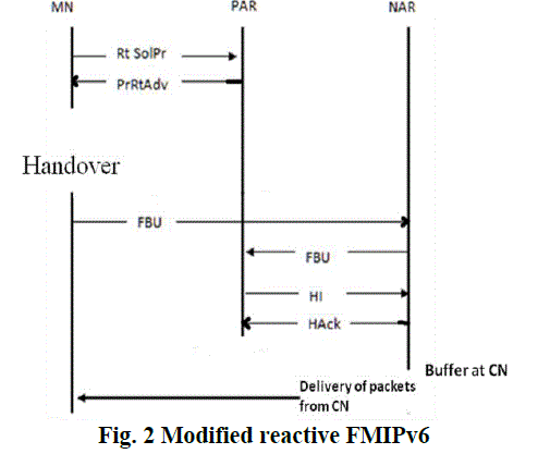 |
| Once the MN is moving to another network, the handover process starts and it originates buffering at the PAR. At the
same time buffer at the CN is also starts buffering of packets and also alerts the buffer at CN for the transmission of
packets with reduced data rare than the actual one. When the buffer at PAR is filled with its capacity it starts losing the
packets. So the number of packets lost reach the buffer at PAR is decreased as a consequence, the packet loss is
reduced in this mode of operation compared to the Reactive FMIPv6. |
| After MN is switched to new network, in response to the BU message, the buffered packets in buffer at CN are
forwarded first. Then the packets from CN are sent to MN through NAR with the actual data rate. As the packets stored
in buffer at CN are forwarded to MN and this process does not involves the tunneling of packets during handover, the
handover latency of modified reactiveFMIPv6 decreases compared to the reactive FMIPv6. |
RESULT AND DISCUSSION |
| Network Simulator version 2 (NS-2) is used as the simulation tool to validate the results as discussed in proposed
method. NS-2 provides two outputs such as network animator (NAM) and a trace file. In order to show the results of
proposed method, the NAM is sufficient as it provides the visual information about the desired network. So, the results
obtained are shown in NAM, which are given below with the analysis of the results followed. For better understanding
of results, first shown the simulation results for reactive FMIPv6 and then followed by modified reactive FMIPv6. |
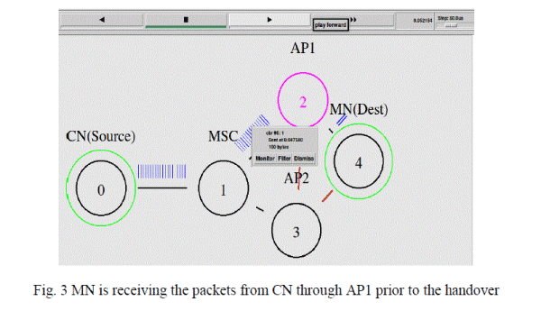
| Reactive FMIPv6: For implementing reactive FMIPv6, created a five node network in which the first node is the
correspondent node (CN) and the fifth node is the mobile node (MN), which are source and destination respectively. In
order to differentiate the source of traffic and destinations from other nodes, they are encircled. To show the handover
from one network to other, require two nodes, they are node 2 and node 3. These nodes are considered as the access
point 1 (AP1) and access point 2 (AP2). For highlighting the AP node from which the MN is receiving packets, that
particular AP node is encircled. |
| Before handover: The following figure depicts the scenario of five nodes. In this the MN is accessing the packets
through the AP1. In NS-2, it facilitates the user to monitor the packets at any point of time. In fig 3, packet 96 is passed
from node 1 to node 2 with the packet length of 100 bytes at 0.0475 sec. |
 |
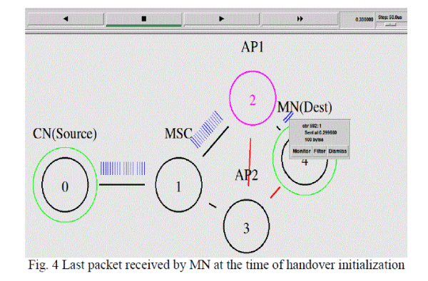
| Calculation of handover latency for reactive FMIPv6: Handover latency is the result of link switching delay and IP
protocol operations. It can be also defined the amount of time that the MN is incapable of receiving the packets from
source. So, the handover latency can be calculated by deducting the last packet received time (before handover) from
the first packet received time by MN (after handover). That is the time taken by MN to switch from AP1 to AP2. The
handover is considered at 0.3sec and at that time the MN receives the last packet before handover as shown in fig 4. |
 |
| The fig 5 shows at what time the mobile node receives the first packet after handover. |
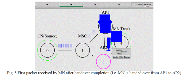 |
| From the above two figures, it is clear that the last packet is received at 0.3sec and the first packet is received at
0.3055sec after handover. So the handover latency for the reactive FMIPv6 is
Handover latency (reactive FMIPv6) = 0.3055-0.3 = 0.0055sec = 5.5msec. |
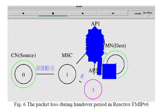
| Packet loss: Reactive FMIPv6 uses a buffer at PAR to reduce packet losses. But still there occurs packet loss due to the
exhaustion of the buffer at PAR. Fig. 6 shows the number of packets lost during handover. The numbers of packets lost
in reactive FMIPv6 are 14. |
 |
| After the handover: The MN receives packets from CN through AP2 after handover. |
| Modified reactive FMIPv6: In the modified reactive handover, in addition to the buffer at PAR another buffer is
deployed at the CN. As discussed in the previous chapter, the usage of buffer at CN improves the handover latency and
packet loss, which are going to see in the following. |
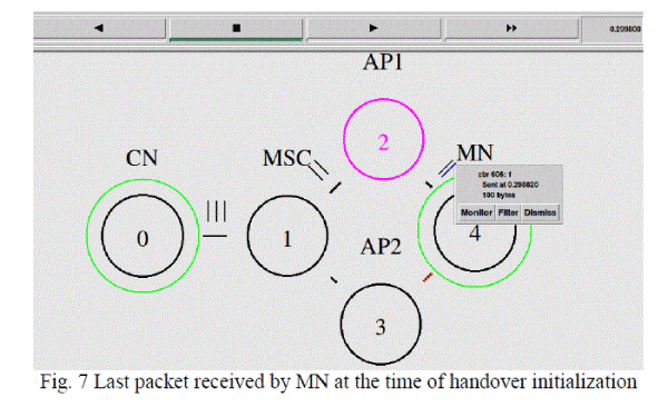
| Calculation of handover latency for modified reactive FMIPv6: Handover latency is the time taken by MN to
switch from AP1 to AP2. As in the earlier, the handover latency can be calculated by deducting the last packet received
time (before handover) from the first packet received time by MN (after handover). |
 |
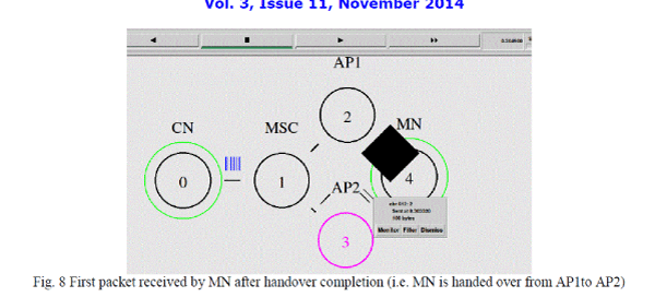 |
| From fig. 7 and fig. 8 it is clear that the last packet is received at 0.3sec and the first packet is received at 0.305sec after
handover. So the handover latency for the modified reactive FMIPv6 is
Handover latency (modified reactive FMIPv6) = 0.305-0.3 = 0.005sec = 5msec. |
| Packet loss: The modified reactive FMIPv6 uses additional buffer at CN along with the one at PAR. During the
handover process, the buffer at PAR informs the buffer at CN to slow down the packet rate from the actual rate. So the
packet losses are less in the modified reactive FMIPv6 as the number of packets reaching AP1 is reduced. |
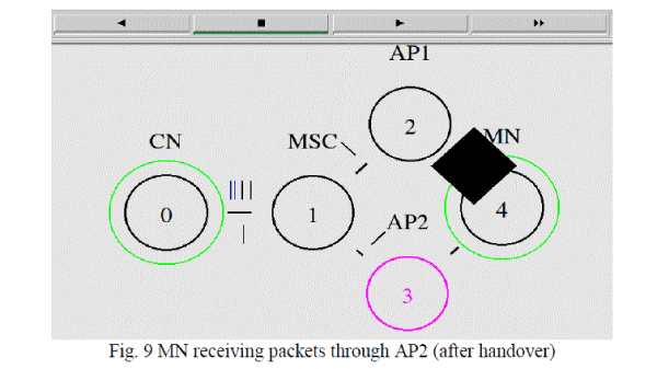
| The fig 7 shows that the decreased interval of packet generation. After the handover is accomplished, the buffer at CN
reset the data rate to the actual data rate. For simple understanding of changes in packet data rate, the actual traffic is
colored with blue and the slow data rate traffic is colored with black. The fig 9 shows the increased data rate (blue
lines) after the completion of handover (after MN is attached to AP2). |
 |
| Performance comparison: Fig 10 shows the handover latencies of reactive FMIPv6 and Modified reactive FMIPv6 in
a graph. |
| Table 1 describes the overall comparison between reactive FMIPv6 and the modified reactive FMIPv6 in terms of
handover latency and the number of packet lost. |
 |
| Hence, from the comparison of two methods, it is clear that the modified reactive FMIPv6 results better than the
reactive FMIPv6. |
CONCLUSION |
| In order to support better QoS for the real-time and non-real time applications like Voice over IP (VoIP), video
conferencing, video streaming in Internet etc., seamless handover is the solution when a Mobile node is roaming across
the network. For the seamless handover, one solution is Reactive FMIPv6.But still there is scope for enhancing the
performance of reactive FMIPv6 and it is proposed in this thesis work called modified reactive FMIPv6. |
| It provides seamless handover than the reactive FMIPv6 by making use of buffer at the CN. In this, buffer plays the key
role in enhancing the handover latency by suppressing tunneling process during handover and also in enhancing packet
losses by decreasing the data rate during handover period. Thus, the modified reactive FMIPv6 has an impact on fast
and reliable handover. |
References |
- Yvette E. Gelogo and Byungjoo Park, âÃâ¬ÃÅReducing Packet Loss for Mobile IPv6 Fast Handover (FMIPv6)âÃâ¬ÃÂ, International Journal of Software Engineering and Its Applications, Vol. 6, No. 1, Jan.2012.
- Salim M. Zaki 1c and ShukorAbdRazak, âÃâ¬ÃÅMitigating Packet Loss in Mobile IPv6 Using Two-Tier Buffer SchemeâÃâ¬ÃÂ, Computer Science Letters, Vol. 3(2) , Jun.2011.
- R.Koodli, âÃâ¬ÃÅFast Handovers for Mobile IPv6âÃâ¬ÃÂ, Internet Draft 2005, available online at:http://www.ietf.org/rfc/rfc4068.txt.
- Johnson, D., Perkins, C., Arkko, J., âÃâ¬ÃÅMobility Support in Ipv6,âÃâ¬Ã RFC3775, 2004, available online at: http://tools.ietf.org/html/rfc3775.
- Lu Hang, Wu Wenming, Fang Jun, âÃâ¬ÃÅProblems with Mobile IP and Their SolutionsâÃâ¬ÃÂ, ZTE Communications, No.2articles, 2004.
- Ruidong Li, Jie Li, Kui Wu, Yang Xiao and Jiang Xie, âÃâ¬ÃÅAn Enhanced Fast Handover with Low Latency for Mobile IPv6âÃâ¬ÃÂ, IEEE Transactions On Wireless Communications, Vol. 7, No. 1, January 2008.
- M. Omar Al-Najeh, K. Abu Bakar, Ali SafaSadiq, K. Z. Ghafoor, âÃâ¬ÃÅAdaptive Packet Buffuring Algorithm Based on Priority and Traffic Throughput for Reducing Packet Loss in Fast Handover for Mobile IPv6âÃâ¬ÃÂ, in IJSCI, Vol.9, No.1, July 2012.
|