Driven by economic, technical and environmental reasons, the energy sector is moving into an era where electrical demand will be met through wide spread installation of distributed resources or what’s known as Distributed Generation Systems. This paper deals with a distributed generation system (DGS) with fixed speed induction generator based wind turbines (FSWTs) which are sensitive and vulnerable to voltage disturbances and reactive power deficiency. Consequently, the control and protection strategies should be prompt and precise to avoid undesired wind generator shut down. In this paper, a distributed generation system with three combined heat and power generators (CHPs) and three fixed speed induction generator based wind turbines (FSWTs) is initially connected to the grid and feeding dynamic load groups. A fast control strategy is proposed to stabilize the system when the distributed generation system (DGS) is islanded from grid after the occurrence of a three phase fault. This includes governor and exciter control of CHPs, reactive power compensation, and load shedding. Simulation is done in PSCAD/EMTDC and results are analyzed.
Keywords |
| DGS, FSWTs, CHPs, governor control, reactive-power compensation, load shedding |
INTRODUCTION |
| The environmental regulations due to green house gas emissions, the electricity business restructuring , and the recent
development in small scale power generation are the main factors driving the energy sector in to a new era, where large
portions of increase in electrical energy demand are met through widespread installation of distributed resources or
what’s known as ‘Distributed Generation Systems’. DGS facilitate electric power generation in proximity of load
centres. As a result, DGS can give commercial consumers various options in a wider range of high reliability- low price
combinations.DGS can operate either in a grid-connected mode or in an islanded mode within a micro-grid. In the
islanded mode of operation, a cluster of DG units serviced by a distribution system is formed to maintain the reliability
of critical loads, mainly when the utility supply is not available. |
| The behaviour of power system is mainly determined by the behaviour and interaction of generators connected to it.
When the penetration of wind generation increases its effect on power system also increases. This leads to careful study
of stability of power system with wind generators. Not only the renewable generation units, but also the increasing
utilization of power electronics devices in a DGS has changed the power system characteristics. Some literatures reveal
that the recent large scale system blackouts are increasingly because of voltage collapses caused by reactive power
deficiency, rather than frequency drops [1]. In addition wind turbines (WTs)’ induction generators are more sensitive to
voltage than conventional synchronous generators, so an induction generator-based WT is more vulnerable to voltage
disturbances. |
| Conventional system protective schemes, such as under frequency load shedding (UFLS) or under voltage loadshedding
(UVLS), may not respond quickly enough after disturbances in the changing power systems [1, 2]. Some
adaptive strategies have been proposed in the literatures [3].However, such adaptive strategies may still have some
problems, for instance, in [3], a centralized UFLS control system encounters the problems of the control commands
transmission delay. Furthermore, such conventional load shedding schemes are not suitable for stabilizing fixed-speed
induction-generator (FSIG)-based WTs during disturbances. An ideal DGS should possess the characteristics of
compatibility and flexibility, which ensures that the system can operate in either grid connection or standalone. |
| Although variable speed doubly-fed induction-generator (DFIG) - based wind turbines are most popular now, many
fixed-speed induction-generator-based wind turbines (FSWTs) installed early are still in operation, therefore it is still
worth investigating fixed speed induction generator based wind turbines. |
| This study proposes a fast control and protective strategy, to enable the FSWTs involved DGSs respond in a timely
manner and avoid undesired disconnections of WTs, which may be caused by generator over-speed protection. |
FAST CONTROL STRATEGY FOR AN ISLANDED DGS |
| The fast control strategy intends to maintain the balance of the generation and the loading in an islanded DGS in a
prompt manner. The main generation units are FSWTs and CHPs. |
A. Fast Control Strategy |
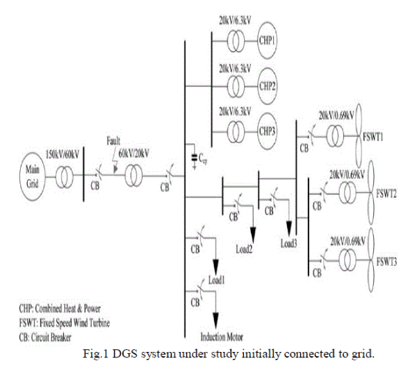
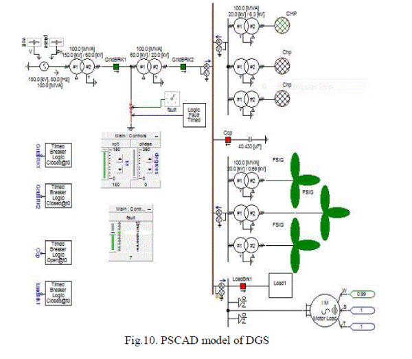
| In this study, initially DGS with three CHPs and three FSWTs is connected to the grid as shown in Fig.1.
After the occurrence of a fault on the grid side, the DGS is islanded permanently. To stabilize the DGS during
islanding, the DG units and loads need to be re-adjusted and re-balanced according to the system status. |
 |
| This Fast control strategy mainly consists of two aspects viz. are Generation control and Load shedding. Generation
control consists of control of active and reactive power of CHPs and FSWTs. If it is inevitable, we have to go for load
shedding. Even this should be based on an optimized priority table. Detailed description of these aspects is given in the
following sections. |
B. Generation Control |
| Generation control for an islanded DGS mainly deals with the control of CHPs generation. It contains three key
operations: |
i. Control mode shifts: |
| Since FSWTs have no further active power and reactive power control ability, CHPs are the major control
objects in generation control. Once an islanding of a DGS is detected, the CHPs’ control mode should shift from Control
Mode 1 to Control Mode 2, as indicated in Fig.2 |
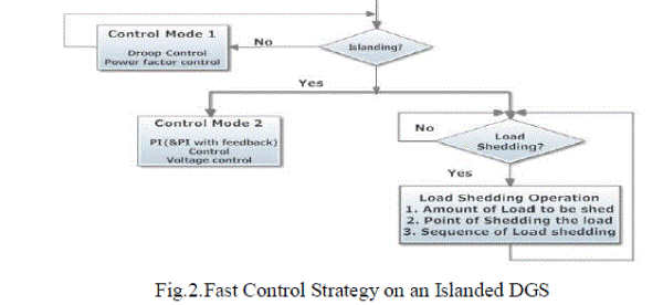 |
| Control Mode 1 is implemented when the DGS is integrated with the main grid. In Control Mode1, the
active power control is Power –frequency droop control; the reactive power control is power factor control. |
| Control Mode 2 is implemented when the DGS is islanded from the main grid. In Control Mode 2, the active power
control is PI (proportional integrator) control, reactive power control is voltage control, but if there is more than one
active power controllable generator, only one governor of these generators can utilize PI controller, the others may
choose PI with a feedback controller [4]. |
ii. CHPs’ releasing reserved generation: |
| After DGS islanding, because of the loss of active power and reactive power exchange from the main grid, the
DGS reserved generation capacity should be adjusted adaptively and promptly. To keep the voltage and frequency in the
required range, the generated active power and the reactive power should be balanced with consumptions. Accordingly,
the adjustable generation units are supposed to release reserved generation to satisfy the possible power deficiency in the
DGS. |
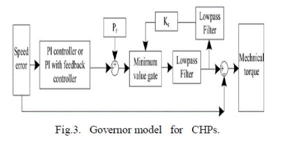
| The active power control is implemented by the CHPs’ governor control, as depicted in Fig. 3, in which the parameter Pr
is the reference power in per unit, Kc is the ambient temperature load limit and their maximum values are both 1.0. |
| If reserved generation is to be released, Pr and Kc need to increase, even into 1.0 to maximize releasing of generation
reservation. |
 |
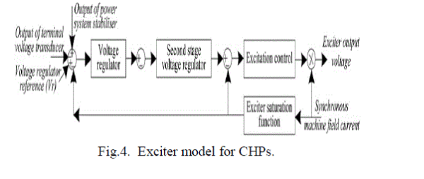
| Regarding the reactive power control for the CHPs, IEEE Alternator Supplied Rectifier Excitation System #2 (AC2A)
[5] as simplified in Fig. 4, is utilized. The voltage regulator reference (Vr) is adjusted from 1.0 under Control Mode 1 to
1.2 under Control Mode 2, in order to release the CHPs’ reserved reactive power. |
 |
iii. Reactive power compensation: |
| Although the CHPs’ adjusting generation is performed immediately after detection of DGS islanding, the
adjusting procedure still takes certain time, that is, several seconds. Assuming there are several FSWTs and a motor in a
DGS, they are all induction machine based, and they are all sensitive to reactive power deficiency. During this period of
time, the WTs’ and the motor’s terminal voltage may not be restored sufficiently to stabilize the FSWTs and the motor.
Therefore once insufficient voltage is detected, the reactive power compensation operation should be performed, that is,
a shunt capacitor Ccp should be switched on. The implementation location of the Ccp is located at the disconnecting point
between the grid and the DGS. The implementation time is decided at the moment when the FSWTs’ terminal voltage
restores to a peak value, which may be still lower than 1.0 pu. The amount of reactive power compensation, fulfilled by
Ccp , is decided by the reactive power deficiency, QDef, of the DGS because of islanding. |
C. Load Shedding |
| If Reserve power capacity Pres is less than the power deficiency Pdef, , then the load shedding command must
be issued. Total amount of load to be shed PLS is given by |
 |
| If more than one load has to be shed, the priority is decided by customer information from the Load Management System
(LMS), for example, the payment of customers, their social importance, their economic characteristics etc. For loads
with the same priority, the sequence of load shedding depends on the loads characteristics. Loads with smaller
dP/dV, dQ/dV, dP/df, |dQ/df| may be shed earlier, the loads with greater dP/dV , dQ/dV , dP/df, |dQ/df| may be shed
later. Such a load shedding sequence should be preset. |
PSCAD/EMTDC IMPLEMENTATION |
| To demonstrate the effectiveness of the fast control strategy, PSCAD/EMTDC [6] is used for power system simulation. |
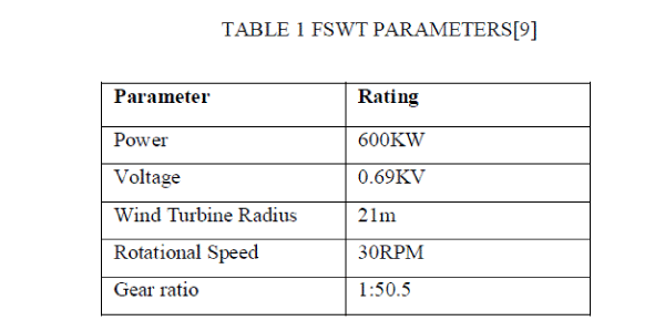
| FSWT Model: |
| Three FSWTs are all rated at 600 kW, 0.69 kV. The mechanical torque [7] is formulated as below |
 |
| where ρ is the air density in kg/m3, R is the wind turbine radius in m, A is the wind turbine rotor area in m2,
vwindis the wind speed in m/s and Cq is the torque coefficient [7]. |
 |
| where ,Cp is the power coefficient, may be expressed by (4), [8] λ is the tip-speed ratio |
 |
 |
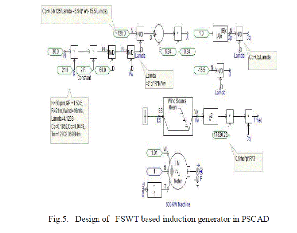 |
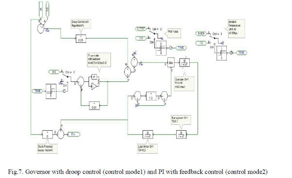
| CHP Model: |
| Three CHPs are all rated at 3.3 MW, 4.5 MVA, and 20KV.Governor control is done by combination of pf droop in
control mode1 and PI control (one CHP) or PI with feedback control (for all other CHPs) in control mode 2. |
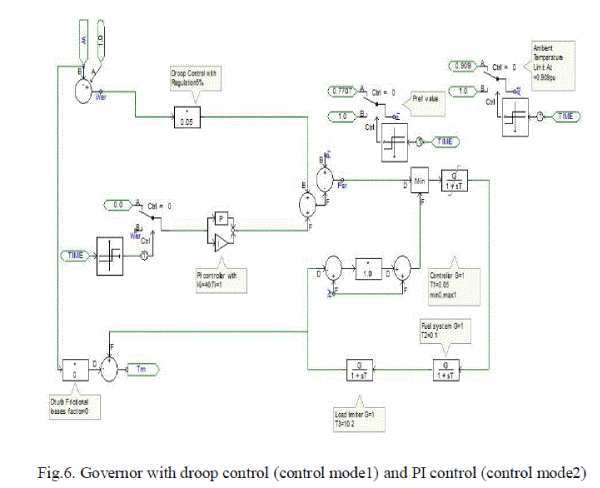 |
| Here, we can see that after islanding along with pf droop control additionally PI control comes into picture. Similarly, for
other CHPs we can see the PI with feedback in Fig7. |
 |
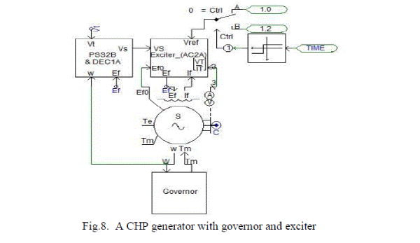
| For Exciter, we are using AC2A type model with available Power system stabilizer PSS2B. A CHP generator can be
shown in Fig.8. |
 |
| Load groups: |
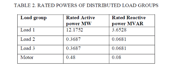 |
 |
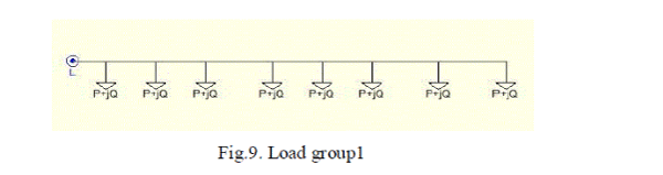 |
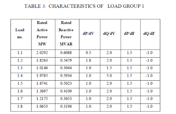
| Load group1 consists of eight loads as shown in Fig 9. They are named as 1.1 to 1.8 from left to right .They have
different dynamic characteristics which are given in Table 3. |
| Overall DGS in PSCAD/EMTDC: |
 |
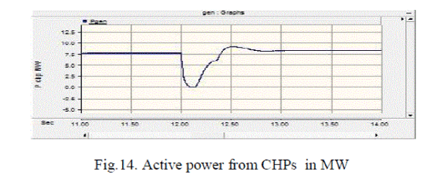
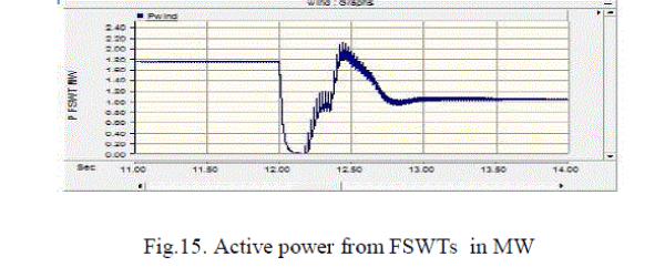
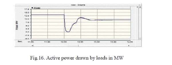
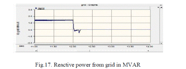
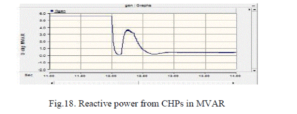
SIMULATION RESULTS AND DISCUSSIONS |
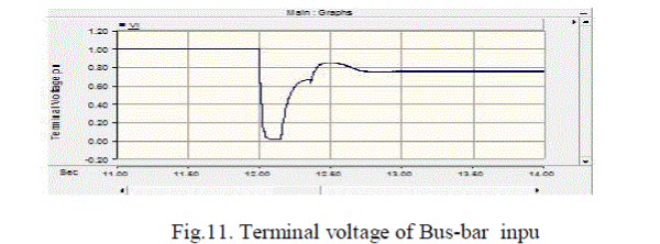
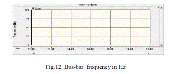
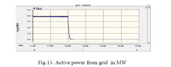
| In the studied scenario, the wind speed is assumed as the rated wind speed 16m/s, and a three-phase-ground fault
occurs at 12 s, on the main grid side. After the fault lasts 150 ms, the DGS is islanded at 12.15 s. Then, the DGS
would try to support its local loads with its own generations, that is, the three WTs and the three CHPs.
The fast control strategy is applied to stabilize the DGS. Simulation is run for about 30 sand voltages and powers at
various nodes are observed. |
 |
 |
 |
 |
 |
 |
 |
 |
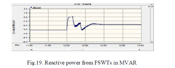 |
| From the results, it is evident that voltage of the system is stabilized very fastly ( <1sec).Here as the final stable
voltage is less than 1pu, the voltage dependent load has decreased and load shedding case is not considered. We have
considered only the simplest case only to verify the control strategy. |
CONCLUSION AND FUTURE SCOPE OF WORK |
| Fast control strategy is proposed, the various components of the DGS are modelled in PSCAD/EMTDC and the
system is simulated to demonstrate the fast control strategy. In this scenario, we haven’t taken up load shedding
operations. Future work can include detailed inclusion of load shedding operation and we can look for coordinated
control that automates the system stabilization. |
References |
- Shah, N., Abed, A., et al. (July 1999): âÃâ¬ÃËUndervoltage load shedding guidelinesâÃâ¬Ãâ¢. Western System Coordinating Council. Available at http://www.wecc.biz/committees/StandingCommittees/PCC/TSS/Shared%20Documents/Undervoltage%20Load%20Shedding%20Guidelines.pdf, access November 2011
- Chuvychin, V.N., Gurov, N.S., Venkata, S.S., Brown, R.E.: âÃâ¬ÃËAn adaptive approach to load shedding and spinning reserve control during underfrequency conditionsâÃâ¬Ãâ¢, IEEE Trans. Power Syst., 1996,11, pp. 1805âÃâ¬Ãâ1810 .
- Seyedi, H., Sanaye-Pasand, M.: âÃâ¬ÃËNew centralized adaptive load-shedding algorithms to mitigate power system blackoutsâÃâ¬Ãâ¢, IET Gener. Transm. Distrib., 2008, 3, pp. 99âÃâ¬Ãâ114.
- Mahat P.: âÃâ¬ÃËControl and operation of islanded distribution systemâÃâ¬Ã⢠PhD thesis, Aalborg University, 2010.
- IEEE PES Energy Development and Power Generation Committee:âÃâ¬ÃËIEEE Std 421.5™-2005, IEEE recommended practice for excitationsystem models for power system stability studiesâÃâ¬Ãâ¢, 2006
- Manitoba HVDC research center: âÃâ¬ÃËEMTDC/PSCAD ManualâÃâ¬Ãâ¢, 2009
- Chen, Z.: âÃâ¬ÃËWind turbine drive train systemsâÃâ¬Ãâ¢, in SÃÆørensen, J.D.,SÃÆørensen, J.N. (Eds.): âÃâ¬ÃËWind Energy Systems, Optimising design andconstruction for safe and reliable operationâÃâ¬Ã⢠(Woodhead PublishingLtd., 2011, 1st edn.), pp. 208âÃâ¬Ãâ246
- Deng, F., Chen, Z.:âÃâ¬ÃËPower control of permanent magnet generator basedvariable speed wind turbinesâÃâ¬Ãâ¢. Proc. Int. Electrical Machines andSystems Tokyo, Japan, November 2009
- Vestas Wind Systems A/S: âÃâ¬ÃËV42/600 Wind Turbine data sheetâÃâ¬Ãâ¢, 2010
|