Problems that arise with the working of an AC induction motor is common these days if left unmonitored. Here a protection system is implemented using which we monitor the working of an AC induction motor during normal conditions and trip conditions. If any problems become evident due to faults that normally happen in the motor like stator faults, rotor faults, bearing faults, eccentricity faults etc., we can either vary the input voltage and current to bring the motor back to normal condition or we can shut down the motor before damaging the stator and rotor components of the motor to point from which recovery is not possible, thus avoiding unexpected failure of the motor and preventing an entire industrial process from shutting down all of a sudden which can be dangerous to the people working in the vicinity and helps save unforeseen expenditure that may result from the above mentioned problems.
Keywords |
| AC induction motor, trip conditions, stator faults, rotor faults |
INTRODUCTION |
| Induction motors are perplexing electro-mechanical devices used in most industrial applications for the transformation
of power from electrical to mechanical form. Induction Motors are utilized worldwide as the workhorse as a part of
mechanical provisions. Such motors are robust machines utilized for general purposes, as well as in risky areas and
serious situations. Broadly useful provisions of induction motors incorporate pumps, transports, machine instruments,
diffusive machines, presses, lifts, and bundling supplies. Then again, requisitions in unsafe areas incorporate
petrochemical and common gas plants, while serious environment provisions for induction motors incorporate grain
lifts, shredders, and gear for coal plants. Moreover, actuation engines are very dependable, oblige low support, and
have moderately high proficiency. In addition, the extensive range of power of induction motors, which is from many
watts to megawatts, fulfils the creation needs of most mechanical methodologies. |
| Be that as it may, induction motors are vulnerable to numerous sorts of issue in industrial requisitions. A motor failure
that is not distinguished in an introductory stage may get cataclysmic and the induction motor may endure serious
harm. Accordingly, undetected motor faults may course into motor failure, which may cause production shutdowns.
Such shutdowns are excessive as far as lost processing time, support takes, and squandered crude materials. |
| The motor faults are because of mechanical and electrical hassles. Mechanical stresses are brought on by overload and
sudden load changes, which can generate bearing faults and rotor bar breakage. Then again, electrical faults are
typically connected with the power supply. Induction motors could be energized from consistent frequency sinusoidal
power supplies or from adjustable speed AC drives. Be that as it may, induction motors are more susceptible to fault
when supplied by AC drives. This is because of the extra voltage stress on the stator windings, the high frequency
stator current components, and the induced bearing currents, initiated by AC drives. Furthermore, motor over voltages
can happen in light of the length of cable connections between a motor and an AC drive. This last effect is initiated by
reflected wave transient voltages. Such electrical hassles may produce stator winding short-circuits and bring about a
complete motor failure. |
| As stated by overviews led, induction motor failures incorporate bearing failures, inter-turn short-circuits in stator
windings, and broken rotor bars and end ring faults. Bearing failures are answerable for roughly two-fifths of all faults. Inter-turn short-circuits in stator windings speak to give or take one-third of the reported faults. Broken rotor bars and
end ring flaws speak to around ten percent of the induction motor faults. |
LITERATURE SURVEY |
| All the faults that occur in an AC induction motor have been analysed. The faults that are likely to happen are rotor
faults, stator faults, eccentricity faults, bearing faults, load faults. Advanced Signal Processing techniques have been
used to detect the faults [12]. Stator current spectral signature analysis is mostly used to identify the faults, this method
used power spectrum of the stator current [2]. Physical parameters like vibration, noise, torque and temperature are
measured using sensors, all these parameters are vital in checking the proper working of the motor [3]. PLC is used for
protection of induction motor as it can monitor more than one parameter simultaneously [6]. |
PROPOSED METHODOLOGY |
| So here a system is designed with an alternative method to prevent the failures that happen in induction motors using a
Programmable Logic Controller (PLC) and sensors to measure the different parameters related to induction motors
such as current, voltage, temperature, speed, and vibration. All these parameters are constantly monitored with the help
of SCADA during the operation of the motor and if any faults were to occur, there will be change in one or more
parameters by which we can take the necessary precautions thus preventing damage to the induction motor. |
COMMON MOTOR FAULTS AND THEIR DIAGNOSIS |
| Numerous faults can occur in an induction motor during its course of operation. These faults if left undetected can lead
to catastrophic failures. The common internal faults can be categorized into two group’s namely electrical faults and
mechanical faults. |
A. Electrical Faults: |
| The following are common electrical faults which can be found in induction motors. |
| 1) Rotor faults: The several reasons for rotor faults are |
| a) During the brazing process in production, non-uniform metallurgical stresses might be incorporated with cage
assembly and these can likewise prompt to failure during operation. |
| b) A rotor bar may be unable to move longitudinally in the slot it occupies, when thermal stresses are forced upon it at
the starting of the motor. |
| c) Heavy end ring can bring about expansive centrifugal forces, which can result in hazardous stresses on the bars. |
| In view of the above reasons, rotor bar may be harmed and all the while unbalance rotor circumstance may happen.
Rotor cage asymmetry brings about asymmetrical distribution of the rotor currents. Because of this, harm to one rotor
bar can result in the harm of encompassing bar and in this manner damage can spread, prompting various bar cracks. If
there should arise an occurrence of a break, which happens in a bar, the broke bar will overheat, and this can result in
the bar to break. Thus, the encompassing bar will carry higher current and therefore they are subjected to considerably
larger thermal and mechanical stresses which might likewise begin to crack. The greater part of the current which might
have flown in the broken bar now will flow in the two bars nearby it. Thus, the huge thermal stresses might additionally
harm the rotor laminations. |
| 2) Stator faults: As stated by many reviews, 35-40 % of induction motor failures are related to stator winding
insulation. A stator turn fault in a motor causes a substantial flow of current to stream and consequently produces
unreasonable heat in the shorted turns. The natural materials utilized for insulation in electric machines are subjected to
disintegration from thermal overloading and cycling, transient voltage stresses on the insulation material, mechanical
stresses, and contaminations. Indeed the best insulation may fall flat rapidly if motor is worked above its temperature limit. As a dependable guideline, the life of insulation is lessened by 50 % for each 10 degrees Celsius increase in the
stator winding temperature above the limit. |
| A couple of mechanical issues that quicken insulation failures are vibration of rotor due to unbalance, detached or worn
bearings, air gap eccentricity, and broken rotor bars. |
B. Mechanical faults: |
| The following are the most common mechanical faults which can be found in induction motors. |
| 1) Air gap eccentricity: Air gap eccentricity is a basic rotor fault of induction machines. This flaw produces the issues
of vibration and commotion. In a healthy machine, the rotor is center-aligned to the stator bore, and the rotor's center
point of revolution is the same as the geometric center of the stator bore. The point when the rotor is not center aligned,
the unbalanced radial forces (unbalanced magnetic pull or UMP) can result in a stator-to-rotor rub, which can bring
about harm to the stator and the rotor. |
| 2) Bearing faults: Bearings are regular components of electrical machine. They are utilized to allow rotary movement
of the shafts. Indeed, bearings are single biggest reason for machine failures. Bearing comprises of two rings called the
internal and the external rings. A set of balls or moving components put in raceways rotate inside these rings. A
continued stress on the bearings reasons weariness failures, usually at the inward or external races of the bearings.
Little pieces break loose from the bearing, called flaking or spalling. These failures bring about harsh running of the
bearings that creates discernible vibrations and increased noise levels. The shaft voltages and currents are also
additional sources for bearing faults. These shaft voltages and currents result from flux disturbances such as rotor
eccentricities. High bearing temperature is another explanation behind bearing failure. The bearing temperature ascent
might be brought on by degradation of the grease or the bearing. The variables that can result in the bearing
temperature ascent include winding temperature ascent, motor operating speed, and temperature distribution within
motor and so on. Continued stress causes parts of the material to break loose, producing confined weariness phenomena
known as flaking or spalling. Once began, the influenced area extends quickly contaminating the grease and bringing
about localized overloading over the whole circumference of the raceway. Contamination and corrosion are the key
factors of bearing failure in light of the harsh environments present in most industrial settings. Bearing corrosion is
produced by the vicinity of water, acids, and deteriorated lubrication. Under and over-lubrication are additionally some
different reason for bearing failure. The unnecessary heating causes the grease to break down, which lessens its
capability to lubricate the bearing components and quickens the failure process. |
| 3) Load faults: In a few requisitions, for example, airplanes, the unwavering quality of gears may be critical in
protecting human lives. Therefore, the detection of load faults (particularly related with gears) has been a critical
research region in mechanical engineering for quite a while. Motors are frequently coupled to mechanical loads and
gears. A few faults can happen in this mechanical arrangement. Examples of such faults are coupling misalignments
and defective gear systems that couple a load to the motor. |
PROGRAMMABLE LOGIC CONTROLLER |
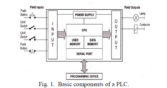
| Programmable Logic Controllers (PLCs), also referred to as programmable controllers, are in the computer family.
They are used in commercial and industrial applications. It was called “Sequence Controller” before it was named
“Programmable Logic Controller (PLC)” by NEMA (National Electrical Manufacture Association) in 1978 and defined
as electronic equipment. The operation of PLC is in the following: |
| Step 1. Read the external input signal, such as the status of keypad, sensor, switch and pulse. |
| Step 2. Using a microprocessor, execute the calculations of logic, sequence, timer, counter and formula according to
the status and the value of the input signal read in the step 1 and pre-write programs saved to get the Corresponding
output signal, such as open or close of relay operation of controlled machine or procedure to control automatic machine
or procedure of manufacture. formula according to the status and the value of the input signal read in the step 1 and
pre-write programs saved to get the Corresponding output signal, such as open or close of relay operation of controlled
machine or procedure to control automatic machine or procedure of manufacture. |
 |
| PLC also can be used to maintain and adjust the production program by editing or modifying the peripheral
equipment’s (personal Computer/handheld programming panel). The common program language of PLC is ladder
diagram. There are stronger functions in PLC with the development and application requirements of electronic
technology, such as position control, network and etc. Output/Input signals are DI (Digital Input), AI (Analog Input), PI
(Pulse Input), DO (Digital Output), AO (Analog Output) and PO (Pulse Output). Thus PLC plays an important role in
the feature industry.In this study, the PLC measures the current, the voltage, the temperature, the vibrations and the
speed of an induction motor through analog inputs. Moreover, it persistently screens the inputs and initiates the initiates
the output as stated by the ladder logic program which is designed to alert the user if any faults occur during the
operation of the induction motor. |
| The PLC used here is a DELTA DVP-EX series manufactured by DELTA electronics. The EX series is the analog
MPU with the lowest cost. It has got a total of 20 MPU points (8DI/6DO, 4AI/2AO). Apart from supporting digital
input and output, the EX series has built-in multiple analog I/O channels and integrates a variety of communication
protocols for constructing a complete control network. EX series is suitable for all kinds of small PLC applications.
PLC is being used because of its many advantages when compared to a microcontroller. The response time of a PLC is
much faster than a microcontroller. The PLC can handle multiple inputs simultaneously. The ladder logic program of a
PLC is simpler and less time consuming than a program developed for a microcontroller. |
PROTECTION SYSTEM OF INDUCTION MOTOR |
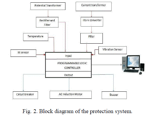
| In Fig.2, a block diagram of the proposed protection system is illustrated. It comprises of voltage and current
measurement, the winding temperature, the vibrations and speed of the rotor. The proposed protection system can be
sub-categorized into 3 groups as the hardware, the measurement and the software. The task of each of the groups are
mentioned in the following sections. |
 |
A. Hardware |
| Here a 0.5 HP 1500 RPM single phase induction motor is connected to the protection system. Single pole double throw
relays are used in this system to stop the motor if it faces any damage warnings and to sound the alarm if the
temperature and vibrations exceed a certain set-point. It also consist of a 5 volt DC power supply circuit which consists
of a step down transformer, a bridge rectifier and a voltage regulator to get a 5 volt DC supply which is the input
voltage of the temperature sensor, the vibration sensor and the IR sensor. |
B. Measurement |
| The voltage and current measurement is done using a voltage transformer and a current transformer respectively.
Bridge rectifiers are connected with both the voltage and current transformers so as to convert the AC values to DC.
These analog values are now sent to the analog inputs of the PLC. For temperature measurement, a LM35 sensor is
used with transformation
ratio of 10 mV for each 1◦C increasing temperature and the analog value of the temperature is sent to the
analog input of the PLC, for vibration measurement a piezoelectric sensor is used where the voltage produced is
proportional to the stress or vibration from the motor and this voltage is given to the analog input of the PLC, for rotor
speed measurement an IR sensor is used where the digital value of the speed is sent to the digital input of the PLC. |
C. Software |
| 1) DELTA WPL SOFT For PLC |
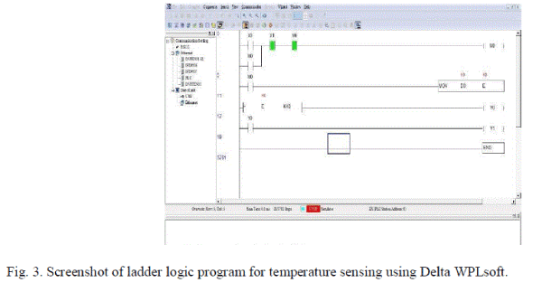
| Delta WPL Soft V2.30 or V.2.33 software is used for design the ladder logic for PLC. Once the ladder logic program is
prepared on the computer, it is loaded into the PLC using a RS-232 cable. Generally, separate software’s are needed for
various types of PLCs. But the principle of ladder logic is same for all. |
 |
| PLC Software. The main difference of PLC software is addressing of element such as normally open, normally close
etc. WPL Soft is a program editor of Delta DVP series PLC for WINDOWS computers. In addition to general PLC
programming and WINDOWS editing functions (e.g. Cut, paste, copy, multi-window display, etc.), WPL Soft also
provides various comment editing as well as other special functions (e.g. register editing and settings, file accessing and
saving, contacts monitoring and setting, etc.). |
| 2) Kepserver EX |
| Kepserver EX programming is a result of Kepware Technologies. This is one of the best programming for interfacing
the ladder logic with the SCADA. With the assistance of this product we can interface various types of PLC. Kepserver
EX is a 32-bit windows application that gives a method for bringing information and data from an extensive variety of industrial devices and systems into customer applications on your windows PC. Kepserver EX falls under the
classification of a "Server" application. It is extremely normal to hear the expression "client/server application" being
used crosswise over numerous software disciplines and business sections. In the streamlined business, it has normally
come to mean the sharing of manufacturing or production data between a mixed bag of applications running from
human machine interface programming and information antiquarians, to vast MES and ERP applications. |
| 3) SCADA |
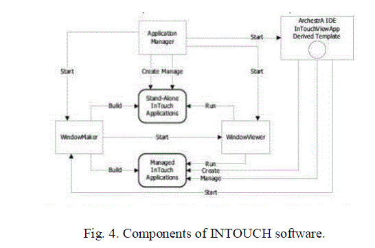
| SCADA is acronym for Supervisory control and Data Acquisitions. Wonderware Intouch programming item from the
Invensys Company gives simplicity of operation of making graphical representation of procedure. A Human Machine
Interface (HMI) programming requisition indicates a graphical representation of a manufacturing environment. The
devices, materials, and methods used to make a product show up as visual components in a HMI provision's windows.
Plant administrators collaborate with an application’s graphical interface to screen and oversee the assembling
methods. |
 |
| A human–machine interface or HMI is the apparatus which shows process information to a human operator, and
through which the human operator controls the methodology. HMI is normally joined to the SCADA framework's
databases and programming projects, to give inclining, symptomatic information, and administration data, for example,
planned upkeep strategies, logistic data, and itemized schematics for a specific sensor or machine, and master system
troubleshooting aides. The HMI system normally shows the data to the operating personnel graphically, as a copy
graph. This implies that the operator can see a schematic representation of the plant being regulated. The HMI package
for the SCADA system ordinarily incorporates a drawing program that the operators or system support staff utilize to
change the way these points are represented in the interface. These representations could be as straightforward as an onscreen
traffic light, which represents the state of a real traffic light in the field, or as mind boggling as a multi-projector
display presentation of the position of all the lifts in a high rise building or all the trains on a route. A vital part of most
SCADA usage is alarm handling. The system screens whether certain alert conditions are fulfilled, when a caution
occasion has happened. When a caution occasion has been identified, one or more actions are taken, (for example, the
initiation of one or more alarm indicators, and maybe the launching of email or quick messages so administration or
remote SCADA administrators are informed). |
CONCLUSION |
| In this project, a protection system has been designed for safeguarding induction motors against all possible faults.
Sensors are used to keep tabs on temperature, vibrations and speed. A current and voltage transformer is used in the
system to check the current and voltage respectively. Assuming that any error is seen throughout online operation of
the motor, a cautioning message shows up on computer and afterward the motor is halted. The point when an unclear flaw happens, the motor stops without giving any warnings. Hence, the flaw might be portrayed and found by the
human operator. The test has been successful in locating the shortcomings and in recouping them. PLC based
protection system is far better that the other protection systems which use timers, contactors, current and voltage relays.
Microcontroller based protection system uses analog to digital conversion card. Therefore by using a PLC all the above
mentioned components can be eliminated and the operator will be able to visualise the operation of the motor and its
electrical parameters. |
References |
- M. E. H. Benbouzid, "A review of induction motors signature analysis as a medium for faults detection," IEEE Transactions on Industrial Electronics, vol. 47, pp. 984-993, 2000.
- Fault detection and protection of induction motors using sensors, 2008, Ramazan Bayindir, Ibrahim Sefa, Ilhami Colak, and Askin Bektas.
- A. Siddique, G. S. Yadava, and B. Singh, âÃâ¬ÃÅA review of stator fault monitoring techniques of induction motors,âÃâ¬Ã IEEE Trans. Energy Convers.,vol. 20, no. 1, pp. 106-114, Mar. 2005.
- M. E. H. Benbouzid, âÃâ¬ÃÅBibliography on induction motors faults detection and diagnosis,âÃâ¬Ã IEEE Trans. Energy Convers., vol. 14, no. 4, pp. 1065-1074, Dec. 1999.
- R. Bayindir and I. Sefa, âÃâ¬ÃÅNovel approach based on microcontroller to online protection of induction motors,âÃâ¬Ã Energy Convers. Manage, vol. 48, no. 3, pp. 850-856, 2007.
- M. G. Ioannides, âÃâ¬ÃÅDesign and implementation of PLC-based monitoring control system for induction motor,âÃâ¬Ã IEEE Trans. Energy Convers.,vol. 19, no. 3, pp. 469-476, Sep. 2004.
- W. T. Thomson, D. Rankin, and D. G. Dorrell, âÃâ¬ÃÅOn-line current monitoring to diagnose airgap eccentricity in large three-phase induction motorsâÃâ¬Ãâ Industrial case histories verify the predictions,âÃâ¬Ã IEEE Trans. Energy Convers., vol. 14, no. 4, pp. 1372-1378, Dec. 1999.
- Precision Centigrade Temperature Sensor (LM 35) Data Sheet National Semiconductor. (2000, Nov.). Available: http://www.national.com
- M. Arkan, D. Kostic-Perovic, and P. J. Unsworth, âÃâ¬ÃÅModelling and simulation of induction motors with inter-turn faults for diagnostics,âÃâ¬Ã Electr. Power Syst. Res., vol. 75, no. 1, pp. 57-66, Jul. 2005.
- M. M. Hodowanec, W. R. Finley, and S. W. Kreitzer, âÃâ¬ÃÅMotor field protection and recommended settings and monitoring,âÃâ¬Ã in Proc. Ind. Appl. Soc.49th Annu. Petroleum Chem. Ind. Conf., New Orleans, LA, pp. 271-284, 23-25 Sep. 2002.
- Neelam Mehala, âÃâ¬ÃÅCondition Monitoring and Fault Diagnosis of Induction Motor Using Motor Current Signature AnalysisâÃâ¬ÃÂ, National Institute of Technology, Kurukshetra, India, 2010.
- B. Mirafzal and A. O. Demerdash, "On Innovative Methods of Induction Motor Interturn and Broken-Bar Fault Diagnostics," IEEE Transactions of Industry Applications, pp. 405-414, 2005.
- A. M. da Silva, R. J. Povinelli, and N. A. O. Demerdash, "Induction Machine Broken Bar and Stator Short-Circuit Fault Diagnostics Based on Three Phase Stator Current Envelopes," IEEE Transactions on Industrial Electronics, 2006.
- M. Benbouzid, M. Vieira, and C. Theys, âÃâ¬ÃÅInduction motorâÃâ¬Ãâ¢s fault detection and localization using stator current advanced signal processing techniques,âÃâ¬Ã IEEE Trans. Power Electron., vol. 14, no. 1, pp. 14-22, Jan. 1999.
- N. Tandon, G. S. Yadava, and K. M. Ramakrishna, âÃâ¬ÃÅA comparison of some condition monitoring techniques for the detection of defect in induction motor ball bearings,âÃâ¬Ã Mech. Syst. Signal Process., vol. 21, no. 1, pp. 244-256, Jan. 2007.
- M. A. Cash, âÃâ¬ÃÅDetection of turn faults arising from insulation failure in the stator windings of AC machines,âÃâ¬Ã Doctoral Dissertation, Dept. of Electrical and Computer Engineering, Georgia Institute of Technology, USA, 1998.
- S. B. Lee and T. G. Habetler, âÃâ¬ÃÅAn online stator winding resistance estimation technique for temperature monitoring of line-connected induction machines,âÃâ¬Ã IEEE Transactions on Industry Applications, Vol. 39, No. 3, pp. 685-694, May/June, 2003.
- K. D. Hurst and T. G. Habetler, âÃâ¬ÃÅA thermal monitoring and parameter tuning scheme for induction machines,âÃâ¬Ã in Conf. Rec. IEEE IASâÃâ¬Ãâ¢97, pp. 136-142, New Orleans, LA, USA,October, 1997.
|