Networked embedded systems have become quite important nowadays, especially for monitoring and controlling the devices. Advances in embedded system technologies have led to the development of residential gateway and automation systems. Apart from frequent power cuts, residential areas suffer from a serious problem that people are not aware about the power cuts due to power disconnections in the transformers, also power theft issues and power wastage in the street lamps during day time exists. So this paper presents a lifestyle system using GSM which transmits the status of the transformer.
Keywords |
| Networked embedded system, Power theft, Power wastage in street lamps, Status of transformer |
INTRODUCTION |
| Generally Automation in Embedded Systems plays major role in various applications. The main function is to make the
system compatible with all devices that can be connected to digital communication networks. Automation reduces
human effort and saves lot of time. This paper is based on Automation in Transformers which mainly uses GSM to
transmit the status of the transformer via message. |
PROPOSED MODEL AND ITS MERITS |
| Most of the residential areas are not aware about the power cuts that are caused due to disconnections in the
transformers. The problem can be solved only if a person had noticed and make a call to the EB station and explain
where the problem exists also, power theft issues and power wastage in street lamps during day time exists. Mainly the
people in the rural areas are affected due to these existing problems. |
| Frequent power disconnections, power theft, power wastage are the main defects in the existing system. In order to
overcome the problems mentioned in the existing system, this system is proposed with GSM based detection and
automation. With this system, we are going to detect the power disconnections in the transformer, automatic ON/OFF
street lights, detection of power theft. All the limitations are overcome and better service is provided. |
METHODOLOGY |
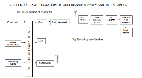
| The power cut issue due to disconnections in the transformer, power theft and a power wastage issue exists in
residential areas. In real time these issues can be rectified by the concept we had proposed. Firstly, the disconnection
problems for example short circuits can be detected by setting up a breaker circuit in the nearby transformer which is
then connected to the PIC microcontroller which senses the status of the transformer i.e., when there is a disconnection
in the transformer the breaker will be tripped so this will be sensed by the controller and the information is send to the
receiver. Secondly, the power wastage problem due to the glow of street lamps in the area can be rectified as follows.
An LDR (Light Dependent Resistor) which is placed on the street lamps which works depending upon the intensity of
the surrounding and is compared with the use of comparator and the street lights are automatically ON/OFF and also if
any problem exists in the LDR circuit, if the lights are glowing even in the day time, this will be sensed by the
controller and the message is sent to the receiver. Thirdly, power theft issues that can be detected by comparing the
voltage value of the current transformer with the reference voltage and the comparator output is given to the controller. If the controller senses the status of the transformer this message will be transmitted to the receiver side through GSM.
The status of the transformer can be displayed either directly in the mobile phone, PC or laptop in EB Station as well as
corresponding In-charge person (lineman). |
BLOCK DIAGRAM OF TRANSFORMER FAULT DIAGNOSIS SYSTEM AND ITS DESCRIPTION |
 |
| A.MICROCONTROLLER: They are destined to play an increasingly important role in revolutionizing various
industries and influencing our day to day life more strongly than one can imagine. The microcontroller has been
recognized as a general purpose building block for intelligent digital systems. A microcontroller is a complete
microprocessor system built on a single IC. Microcontrollers were developed to meet a need for microprocessors to be
put into low cost products. Building a complete microprocessor system on a single chip substantially reduces the cost
of building simple products, which use the microprocessor's power to implement their function, because the
microprocessor is a natural way to implement many products. |
| B.MAJOR FEATURES OF MICROCONTROLLER PIC 16F877A: 16 Bit CPU optimized for control applications,
Extensive Boolean processing (Single - bit Logic) Capabilities, On - Chip Flash Program Memory, On - Chip Data
RAM, Bi-directional and Individually Addressable I/O Lines, Multiple 16-Bit Timer/Counters, Full Duplex UART,
Multiple Source / Vector / Priority Interrupt Structure, On - Chip Oscillator and Clock circuitry, On - Chip EEPROM,
SPI Serial Bus Interface, Watch Dog Timer. |
| C.SHORT CIRCUIT BREAKERS: A circuit breaker [3][10] is an automatically operated electrical switch designed to
protect an electrical circuit from damage caused by overload or short circuit. Its basic function is to detect a fault
condition and, by interrupting continuity, to immediately discontinue electrical flow. Unlike a fuse, which operates
once and then must be replaced, a circuit breaker can be reset (either manually or automatically) to resume normal
operation. Circuit breakers are made in varying sizes, from small devices that protect an individual household appliance
up to large switchgear designed to protect high voltage circuits feeding an entire city. |
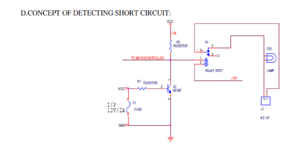 |
| In the above circuit, when there is no short between wires there is a normal flow of power. At this condition
the load (40W bulb) will be glowing. When the two wires are shorted the then the load will be off indicating that the
two wires are shorted. The collector output of the transistor is given to the controller as input. |
| E.AUTOTRANSFORMER: An autotransformer [10] (sometimes called auto step down transformer) is an electrical
transformer with only one winding. The "auto" (Greek for "self") prefix refers to the single coil acting on itself and not
to any kind of automatic mechanism. In an autotransformer portions of the same winding act as both the primary and
secondary. The winding has at least three taps where electrical connections are made. Autotransformers have the
advantages of often being smaller, lighter, and cheaper than typical dual-winding transformers, but autotransformers
have the disadvantage of not providing electrical isolation. |
| Autotransformers are often used to step up or step down voltages in the 110-117-120 volt range and voltages in the
220-230-240 volt range—for example. Providing 110 or 120V (with taps) from 230V input, allowing equipment
designed for 100 or 120 volts to be used with a 230 volt supply (as in using US electrical equipment in with higher
European voltages). |
| F.CONCEPT OF THEFT POWER DETECTION: |
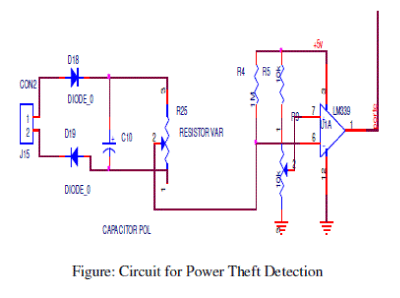 |
| In the above circuit current transformer is used because the input from auto transformer is maximum that the circuit
can’t bear the high voltage. The current transformer will measure the current from the auto transformer and the high
voltage will be converted to a voltage below 5V which is the operating voltage of the controller. When the auto
transformer is varied the load (40W bulb) is made on which indicates there is a power theft. This is done by using a
comparator with reference voltage as 3.5V. When the input voltage is more than the reference voltage there will be
theft. |
 |
| G.CURRENT TRANSFORMER: Instrument transformers means current transformer &voltage transformer are used in
electrical power system for stepping down currents and voltages of the system for metering and protection purpose.
Actually relays and meters used for protection and metering, are not designed for high currents and voltages. |
| High currents or voltages [10] of electrical power system cannot be directly fed to relays and meters. CT steps down
rated system current to 1 Amp or 5 Amp similarly voltage transformer steps down system voltages to 110V. The relays
and meters are generally designed for 1 Amp, 5 Amp and 110V |
| H.LDR [Light Dependent Resistor]: |
 |
| A photo resistor is an electronic component whose resistance decreases with increasing incident light intensity. It can
also be referred to as a light-dependent resistor (LDR), or photoconductor.A photo resistor [4] is made of a highresistance
semiconductor. If light falling on the device is of high enough frequency, photons absorbed by the
semiconductor give bound electrons enough energy to jump into the conduction band. The resulting free electron (and
its hole partner) conduct electricity, thereby lowering resistance. |
| A photoelectric device can be either intrinsic or extrinsic. In intrinsic devices, the only available electrons are in the
valence band, and hence the photon must have enough energy to excite the electron across the entire band gap.
Extrinsic devices have impurities added, which have a ground state energy closer to the conduction band since the
electrons don't have as far to jump, lower energy photons (i.e. longer wavelengths and lower frequencies) are sufficient
to trigger the device. |
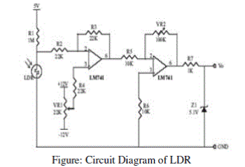
| I.AUTOMATION OF STREET LAMPS: For automation in the street lamps LDR is used. Using the LDR (Light
Dependent Resistor) sensor whose resistance is varied manually the street lights are glow automatically. |
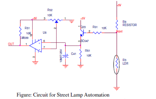 |
| The intensity of surrounding is measured and set to a value say reference voltage is 2.5V and if the intensity is below
2.5V the lights are made ON automatically and if the LDR senses the voltage above 2.5V the lights are made OFF
automatically. And also if there is any problem in LDR say like if street lamps are kept glowing even in the day time
the status will be send to the receiver side so that they can view in which location the fault occurred and clear the
problem. And this status will also be seen by the public on the transmitter side. |
 |
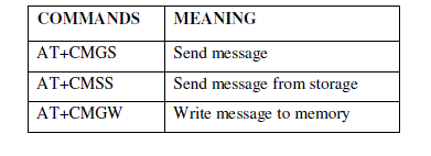
| J.GSM MODULE: GSM is global system [3] for mobile communication which is a wireless technology it uses SIM
card which is the key feature of GSM. |
 |
RESULT AND DISCUSSION |
| This SIM card [9] allows GSM network to quickly move information from one GSM to another. With this GSM
technology the speed of communication is improved. The Global System for Mobile (GSM) communication is the
Second Generation of mobile technology. Although the world is moving towards Third and Fourth generation but GSM
has been the most successful and widespread technology in the communication sector. GSM technology paved a new
way for mobile communication. |
 |
 |
| This project is based on microcontroller programming. The program is written in Embedded C language and is
converted into Hex file which is loaded into the microcontroller through Win PIC flash programmer. After compiling
program in μcontroller flash compiler, it is loaded into PIC 16F877A microcontroller with the help of universal
program burner kit FP8903 programmer which is connected to computer. After successful program burning,
microcontroller becomes ready for use. In testing, after successful program loading, microcontroller is mounted on its
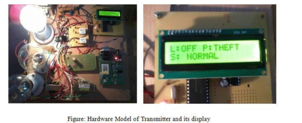
base and hardware becomes ready for testing. If there is any short circuit in the transformers, if any theft occurred, if
lights are kept glowing in day time all these faults are displayed in the LCD as shown above. The above snapshot of
transmitter shows the message in the LCD as L: OFF P: THEFT S: NORMAL. |
| The purpose of displaying this message is that the public can also view the status of the transformer. |
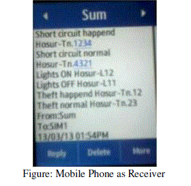 |
| The receiver side snapshot is shown in the mobile phone. The received information will contain the location and ID
number of the transformer in which the fault is happened. |
CONCLUSION |
| In rural areas people suffer due to existing problem because they are not aware of power cut problems and also power
thefts are in practice which the government does not know. By implementing our system these problems are
automatically detected using GSM. Power wastage is more when street lights are kept on glowing even in the morning.
So this can be minimized by our system by automatic ON/OFF of street lights using LDR concept. With our proposed
system we can provide better service and customer satisfaction to the public. |
| In our proposed system we had used GSM technology to transmit the status of the transformer. The status of the
transformer can be transmitted using 3G and 4G technology as a future enhancement along with the detection of
additional parameters like temperature and oil level of the transformer. |
References |
- Jong-Wook Kim, Byung Koo Park, SeungCheolJeong, SW.Kim, Poo Gyeon Park, "Fault Diagnosis of a Power Transformer Using an Improved Frequency-Response Analysis," IEEE Trans. Power Del., vol. 20, no. 1, Jan. 2005.
- W. J. McNutt, W. M. Johnson, R. A. Nelson, R. E. Ayers, "Power Transformer Short-Circuit Strength-Requirements, Design, and Demonstration," Power Apparatus and Systems, IEEE Transactions on, vol. PAS-89, pp. 1955-1969, 1970.
- Vadirajacharya.K, AshishKharche, Harish Kulakarni, VivekLandage, âÃâ¬ÃËâÃâ¬ÃËTransformer Health Condition Monitoring Through GSM TechnologyâÃâ¬Ã International Journal of Scientific & Engineering Research Volume 3, Issue 12, December-2012.
- Denardin, Gustavo.W âÃâ¬ÃËâÃâ¬ÃËAn intelligent system for street lighting monitoring and controlâÃâ¬Ã Power Electronics Conference, 2009. COBEP '09. Brazilian.
- M. Florkowski, J. Furgal, "Identification of winding faults in electric machines using a high frequency method," 2007 IEEE International Coneference on Electric Machines & Drives, IEMDC '07, pp. 590-595.
- M. Wang, A. J. Vandermaar,K. D. Srivastava, "Improved detection of power transformer winding movement by extending the FRA high frequency range," IEEE Trans. Power Del., vol. 20, pp. 1930-1938, 2005.
- M. Wang, A. J. Vandermaar. K.D.Srivastava, "Transformer winding movement monitoring in service-key factors affecting FRA measurements," IEEE Electrical Insulation Magazine, vol. 20, pp. 5-12. 2004.
- AT Commands GSM Reference Guide, Revision A. 2003.
- BajjuriPraneeth Kumar &BodaVamsee Krishna Babu, âÃâ¬ÃÅSMS Remote ControllerâÃâ¬Ã paper presented in Embedded System âÃâ¬ÃâFall 2005.
- Ali Kazemi&Casper Labuschagne ,âÃâ¬ÃÅProtecting Power Transformers from Common Adverse ConditionsâÃâ¬ÃÂ, paper presented at the Ga-Tech and the Western Protective Relay Conferences, New BerlinâÃâ¬Ã in 2005.
|