Keywords
|
| DTMF technology, Home Security System, Wireless communication, Digital telephony. |
INTRODUCTION
|
| The main objective of this system is to unlock a door by a mobile phone using a unique code entered through the keypad of the phone. Opening and closing of doors involves human to be physically involved in to the task. In this cell phone controlled, password protected door locking system, the opening and closing of a door is achieved by using a mobile phone. The owner can call to a mobile phone stacked to the system which in turn is connected to the door motor that can open/close the door by entering the password. This method is very convenient as one doesn?t have to get down of his car to open/close the door physically [6]. The cell phone in the system is kept in auto answer mode. So, after a ring the cell phone accepts the call and starts voice transmission. Now for the button pressed, the DTMF tones are fed to the circuit and the corresponding actions are performed [1]. As interest in wireless communication continues to grow, the remote controlled systems are increasingly being integrated into everyday life. The results of this integration are end-users possessing less and less technical knowledge of the technology. For example, consider the application of mobile robots in the health care industry, where the intended end users are patients themselves. In this case, the need for simplified, reliable, and user-friendly robot designs is of almost importance. |
| Mobile phones today became very popular an essential entity for one and all and so, for any mobile based application there is great reception. Wireless controlled systems utilize RF circuits. However, the use of RF contributes to enhancing the already mysterious nature of communication strategies, which had limitations like limited range, limited frequency ranges and controls. But a mobile phone controlled systems can hold up these limitations. It has a robust control, unlimited range (coverage area of the service provider), and we can have as much as 12 controls. |
LITERATURE SURVEY
|
| The DTMF technology is associated with digital telephony and provides two selected o/p frequencies (One high band and one low band). The DTMF technique consist of 16 common alphanumeric characters (0-9, A-D, *, #) on the telephone. Each characters is uniquely referenced by selecting one of the four low band frequencies associated with the matrix rows, coupled with selecting one of the four high band frequencies associated with the matrix columns [1]. |
| Corresponds to each character, there is unique tone frequency given by, |
 |
| Where ωl and ωh are the low and high frequencies of the sine waves being used, A & B are the amplitude of the signals and φ is the initial phase shifts. |
| [2] Presented an idea to water irrigation in the smart farm using DTMF communication and live video transmission of process parameter. This paper summarizes the controlled irrigation system in the Indian agriculture segment. The idea suggested here is based on cell phone controlled water management system in which a user can make a video call to the cell phone placed at farm site called as a receiver. Receiver mobile is kept in auto answer mode; it will accept the call and starts the video transmission. During the course of call if user pushes any button, corresponding Dual Tone Multi Frequency (DTMF) will be send to receiver mobile. That DTMF received at receiver is fed to microcontroller via DTMF decoder IC. Microcontroller is pre programmed to take any decision for corresponding key such as turn ON/OFF the pump, rotate the camera to see the status of soil etc. So this is the simple farm water management system which can be controlled by farmer from any place and avoid lot of efforts. |
| This work can be extended to control the home appliances such as A.C, Fan, Refrigerator, T.V, Heater, Washing machine and even a door also. So motivated from this background this system have been implemented and the results are verified with small model to open and close the door with password protection. |
THE CELL PHONE CONTROLLED, PASSWORD PROTECTED DOOR LOCKING SYSTEM
|
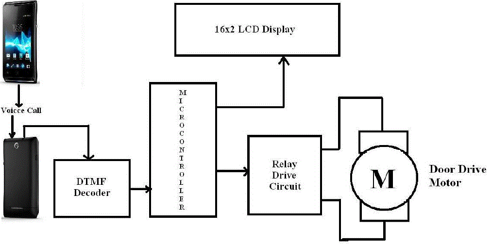
| This work is based on the concept of DTMF (dual tone multi – frequency) technology. All numeric button on the keypad of a mobile phone generates a unique frequency when pressed. These frequencies are decoded by the DTMF decoder IC at the receiving end which is fed to the microcontroller. If this decoded values i.e. code pressed by user matches with the password stored in the microcontroller, then the microcontroller initiates a mechanism to open the door through a motor driver interface as shown in fig.1. |
| The user in order to open the door should make a voice call to the phone which is stacked with the controller unit acting as receiver mobile. This receiver mobile is kept in auto answer mode. So after a ring it will automatically accept the call. Now if user press any button on keypad of phone, the tone corresponds to that button is sent to other end. This tone is fed to DTMF Decoder, where the DTMF frequency is converted in to the equivalent digital form. For example, if 2 is pressed on the keypad, the output of the decoder will be 0010. This digital information is given to the microcontroller. The Microcontroller is pre-programmed to take decision corresponds to input button pressed. A 16x2 LCD display is interfaced with the control unit to display instructions to user. Depending upon the user password, controller will decide to open/close the door if the user get authenticate, by using relay drive circuit and motor. |
CIRCUIT DIAGRAM
|
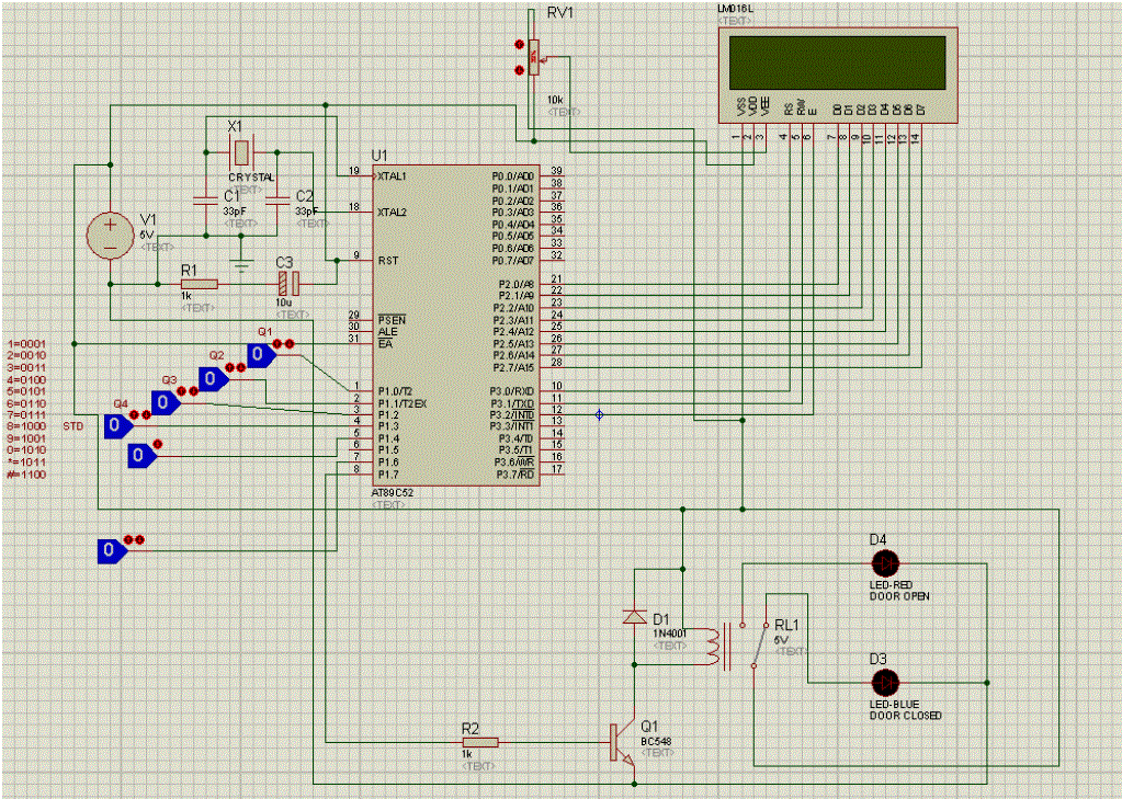
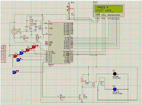
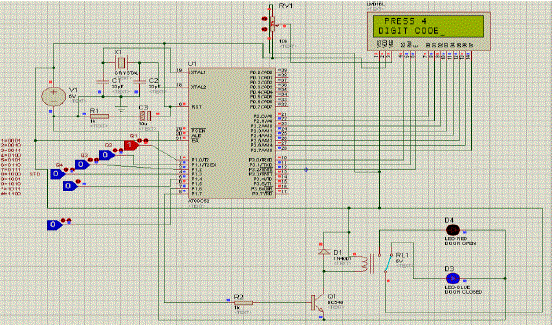
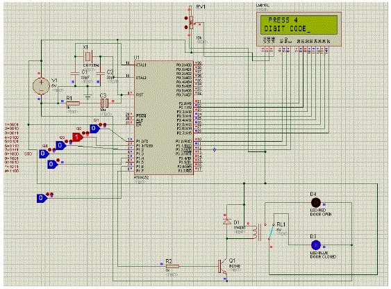
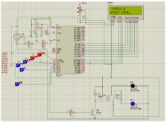
| Fig. 2 illustrates the actual circuit that has been used to obtain the working model of cell phone controlled, password protected door locking system. It consists of Microcontroller, Inverter, motor driver ckt and the DTMF Decoder. Initially microcontroller accepts binary input from DTMF decoder MT8870 (Not shown in circuit diagram). Corresponding to the received tone, microcontroller takes decision to turn motor clockwise or anticlockwise to OPEN/CLOSE the door respectively. |
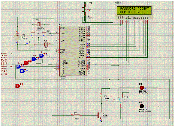
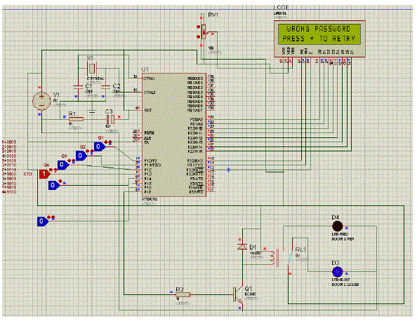
| Digital information coming from DTMF decoder (Not shown in Circuit diagram) is fed to the microcontroller. Microcontroller first of all checks whether the STD bit high or low. This STD bit indicates the detection of valid tone pair on DTMF decoder (MT8870). Then the algorithm start for checking the next button pressed. EA pin of Microcontroller made high to execute the program. Relay drive circuit consist of relay, NPN transistor BC 548, resistor of 1k and a diode 1N4001 shunted with relay. When control unit accepts the password, pin P1.7 of port P1 goes high this will turn on the transistor and relay which actually isolates the motor supply from circuit power supply will make transaction from NC position to NO position. In this way the door will be opened by rotating the motor in clockwise direction. Similarly when P1.7 is low, relay will be at NC position and the motor will rotate till it closes the door. Two LEDs in above circuit indicates opening and closing of the door. |
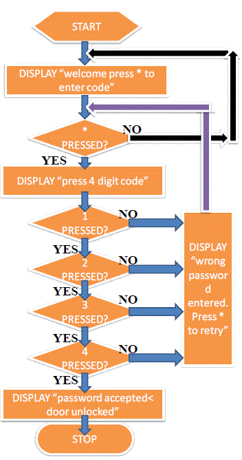
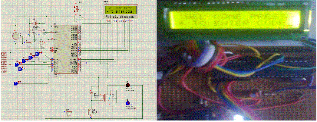
| Algorithm starts with checking the STD bit of DTMF decoder which indicates the detection of valid tone pair on DTMF decoder (MT8870). The 16x2 LCD display will show “WEL-COME PRESS * TO ENTER CODE”. The user may press * to enter 4 digit passwords, this is the starting point where user gets space to enter the password. After pressing * the display will show the message “PRESS 4 DIGIT CODE”. Here user may star to press his high security password. If password entered is wrong then message will be display “WRONG PASSWORD ENTERED. PRESS * TO RETRY”. If password entered is correct then message will be display “PASSWORD ACCEPTED DOOR UNLOCKED”. |
CONCLUSION
|
| From this experimentation we conclude that it is feasible to implement the Cell Phone Controlled, Password Protected Door Locking System which is in turn illustrate the use of DTMF technology for control of remote applications. It is possible to provide high security protection to home, banks and the places where the confidentiality, privacy and security is to be preserved |
Tables at a glance
|
 |
| Table 1 |
|
Figures at a glance
|
 |
 |
 |
 |
 |
| Figure 1 |
Figure 2 |
Figure 3 |
Figure 4 |
Figure 5 |
|
 |
 |
 |
 |
 |
| Figure 6 |
Figure 7 |
Figure 8 |
Figure 9 |
Figure 10 |
|
References
|
- AshishJadhav, Mahesh Kumbhar and MeenakshiPawar, „Cell phone Controlled ground Combat Vehicle?, International Journal ofComputer and communication engineering Vol. 1, No. 2, ISSN: 2010-3743, pp 114-116, July 2012.
- AshishJadhav, MinakshiPawar, Mahesh Kumbhar and Mahesh Walunjkar, “Smart farm water management system using DTMFcommunication and live video transmission of process parameter”, International conference on Electronics and Electrical Engineering pp74-79, ISBN 978-93-81693-67-4 July 2012.
- AshishJadhav, MinakshiPawar, Mahesh Kumbhar, Mahesh Walunjkar And TejasJadhav, “Advanced design for implementing Dual-Tone Multi-Frequency (DTMF) as an alternative mean of communication to RF communication”, International Journal Of ElectronicsAnd Communication Engineering & Technology (IJECET), ISSN 0976 – 6464(Print), ISSN 0976 – 6472(Online) Volume 3, Issue 2, pppp 263-270, July-September 2012.
- AshishJadhav, Mahesh Kumbhar and Mahesh Walunjkar, “Use of 4G in the age of Robotic Communication and Wireless ControlledVehicles ”, International Journal of Innovative Research in Computer and Communication Engineering Vol. 1, Issue 5, ISSN (Print) : 2320 – 9798, ISSN (Online): 2320 – 9801, (pp 1118-1124) July 2013
- AshishJadhav, “Cell phone Controlled ground Combat Vehicle”, LAP LAMBERT Academic Publishing is a trademark of AVAkademikerverlag GmbH & Co. KG Heinrich-Böcking-Str. 6-866121, Saarbrücken, Germany. ISBN Number: (978-3-659-27804-4), (pp1-97), Oct. 2012
- AshishJadhav, Mahesh Kumbhar and Mahesh Walunjkar, “Cell Phone Controlled Applications and systems based on DTMF signalingtechnology” LAP LAMBERT Academic Publishing is a trademark of AV Akademikerverlag GmbH & Co. KG Heinrich-Böcking-Str. 6-866121, Saarbrücken, Germany. ISBN Number: (978-3-659-44474-6), (pp 1-231), July 2013
|