The space vector modulation (SVPWM) of Brushless DC motor (BLDC) is different from that of permanent magnet synchronous motor for its turn-off phase and trapezoidal back electromotive force. To overcome these problems, a SVPWM method is presented in this paper. The application of SVPWM to Brushless AC drives has been investigated extensively. This paper describes its application to BLDC drives and highlights the essential differences in its implementation, as regards torque estimation and the representation of the inverter voltage space vectors. In order to control the torque effectively and directly, the torque is calculated according to the back electromotive force and three phase current. According to the torque error between the given torque and actual torque, the best voltage vector is selected and the dynamic performance of BLDC motor direct torque control system is guaranteed. MATLAB/Simulink is used analyse the simulated results and is shown that SVPWM results in a faster dynamic response.
Keywords |
| Brushless DC (BLDC) drives, Space Vector Modulation (SVPWM), SIMULINK, PI control. |
INTRODUCTION |
| Since 1980‟s new design concept of permanent magnet brushless motors has been developed. The Permanent magnet Brushless
motors are categorized into two types based upon the back EMF waveform, brushless AC (BLAC) and brushless DC (BLDC)
motors [2]. BLDC motor has trapezoidal back EMF and quasi-rectangular current waveform. BLDC motors are rapidly becoming
popular in industries such as Appliances, HVAC industry, medical, electric traction, automotive, aircrafts, military equipment,
hard disk drive, industrial automation equipment and instrumentation because of their high efficiency, high power factor, silent
operation, compact, reliability and low maintenance [1]. |
| To replace the function of commutators and brushes, the BLDC motor requires an inverter and a position sensor that detects rotor
position for proper commutation of current. The rotation of the BLDC motor is based on the feedback of rotor position which i s
obtained from the hall sensors. BLDC motor usually uses three hall sensors for determining the commutation sequence. In BLDC
motor the power losses are in the stator where heat can be easily transferred through the frame or cooling systems are used in
large machines. BLDC motors have many advantages over DC motors and induction motors. Some of the advantages are better
speed versus torque characteristics, high dynamic response, high efficiency, long operating life, noiseless operation and higher
speed ranges [2]. |
| Up to now, over 80% of the controllers are PI (Proportional and integral) controllers because they are facile and easy to
understand [3]. The PI control method is a linear control method and do not work well in some discrete-time system. This is
because controlled planes become nonlinear in variable sampling systems. Variable sampling systems describe a class of
systems whose sensor outputs are obtainable only at some situations not specified by the sampling mechanism. The BLDC
motor usually uses three or more Hall sensors to obtain rotor position and speed measurements. There are only a few sensors
available to the motor. The measurement would be available only at discrete instances. Depending on the number of poles, there
may be six or twelve sensor pulses per rotation. The sampling time thus becomes a variable according to the motor speed. Fuzzy
logic can be considered as a mathematical theory combining multi-valued logic, probability theory, and artificial intelligence to
simulate the human approach in the solution of various problems by using an approximate reasoning to relate different data sets
and to make decisions. It has been reported that fuzzy controllers are more robust to plant parameter changes than classical PI
controllers and have better noise rejection capabilities. The computer simulation plays very important roles in research and
development of power electronic devices because of its high maneuverability, low cost and ability to speed up system implementation. The SIMULINK is a model operation programmer and the simulation model can be easily developed by
addition of new sub-models to cater for various control functions. |
| In this paper, we propose the Field oriented control with Space vector modulation (SVPWM) for BLDC motor drive. SVPWM
was originally developed for induction machine drives and directly controls the flux linkage and electromagnetic torque,
considering the electrical machine, the power electronic inverter and the control strategy at the system level. A relationship is
established between the torque, the flux and the optimal inverter switching so as to achieve a fast torque response. It exhibits
better dynamic performance than conventional control methods, such as vector control, is less sensitive to parameter variations,
and is simpler to implement. DTC has been successfully applied to induction machines [10], [11], and, more recently, to BLAC
machines [12], [13]. This paper considers the application of direct torque control to a three-phase BLDC drive operating in the
120 conduction mode to achieve instantaneous torque control and reduced torque ripple.
The paper is organized as follows: Section 2 explains about construction and operating principle of BLDC motor, Section 3
introduces the field oriented control for SVPWM, Section 4 discusses about current and voltage transformations. The simulation
results are presented in detail in Section 5 and Section 6 concludes the paper. |
CONSTRUCTION AND OPERATING PRINCIPLE |
| BLDC motors are a type of synchronous motor. This means the magnetic field generated by the stator and the magnetic
field generated by the rotor rotates at the same frequency. BLDC motors do not experience the “slip” that is normally seen in
induction motors. BLDC motor is constructed with a permanent magnet rotor and wire wound stator poles. |
| A. Stator |
| The stator of a BLDC motor consists of stacked steel laminations with windings placed in the slots that are axially cut along
the inner periphery. Most BLDC motors have three stator windings connected in star fashion. Each of these windings is
constructed with numerous coils interconnected to form a winding. One or more coils are placed in the slots and they are
interconnected to make a winding. Each of these windings is distributed over the stator periphery to form an even numbers of
poles. |
| B. Rotor |
| The rotor is made of permanent magnet and can vary from two to eight pole pairs with alternate North (N) and South (S) poles.
Based on the required magnetic field density in the rotor, the proper magnetic material is chosen to make the rotor. Ferrite
magnets are used to make permanent magnets. Nowadays, rare earth alloy magnets are gaining popularity. |
| C. Hall Sensors |
| The commutation of a BLDC motor is controlled electronically. To rotate the BLDC motor, the stator windings should be
energized in a sequence. It is important to know the rotor position in order to understand which winding will be energized
following the energizing sequence. Rotor position is sensed using Hall effect sensors embedded into the stator. Most BLDC
motors have three Hall sensors embedded into the stator on the non-driving end of the motor. Whenever the rotor magnetic
poles pass near the Hall sensors, they give a high or low signal, indicating the N or S pole is passing near the sensors. Based on
the combination of these three Hall sensor signals, the exact sequence of commutation can be determined. |
| D. Theory of operation |
| Each commutation sequence has one of the windings energized to positive power the second winding is negative and the third
is in a non-energized condition. Torque is produced because of the interaction between the magnetic field generated by the
stator coils and the permanent magnets. Ideally, the peak torque occurs when these two fields are at 90° to each other and falls
off as the fields move together. In order to keep the motor running, the magnetic field produced by the windings should shift
position, as the rotor moves to catch up with the stator field [2]. |
| E. Commutation Sequence |
| Every 60 electrical degrees of rotation, one of the Hall sensors changes the state. It takes six steps to complete an electrical
cycle. In Synchronous, with every 60 electrical degrees, the phase current switching should be updated as shown in Table 1.
However, one electrical cycle may not correspond to a complete mechanical revolution of the rotor. The number of electrical
cycles to be repeated to complete a mechanical rotation is determined by the rotor pole pairs. For each rotor pole pairs, one
electrical cycle is completed. So, the number of electrical cycles/rotations equals the rotor pole pairs. A 3-phase bridge inverter
is used to control the BLDC motor. There are six switches and these switches should be switched based on the Hall sensor inputs. The Pulse width modulation techniques are used to switch ON or OFF the switches. To vary the speed, these signals
should be Pulse Width Modulated (PWM) at a much higher frequency than the motor frequency. The PWM frequency should
be at least 10 times that of the maximum frequency of the motor. When the duty cycle of PWM is varied within the sequences,
the average voltage supplied to the stator reduces, thus reducing the speed. Another advantage of having PWM is that, if the DC
bus voltage is much higher than the motor rated voltage, the motor can be controlled by limiting the percentage of PWM duty
cycle corresponding to that of the motor rated voltage. This adds flexibility to the controller to hook up motors with different
rated voltages and match the average voltage output by the controller, to the motor rated voltage, by controlling the PWM duty
cycle. The speed and torque of the motor depend on the strength of the magnetic field generated by the energized windings of
the motor, which depend on the current through them. Therefore adjusting the rotor voltage (and current) will change the motor
speed. |
 |
FIELD ORIENTED CONTROL FOR SVPWM |
| In Field Oriented Control, motor currents and voltages are manipulated in the d-q reference frame of the rotor. This means that
measured motor currents must be mathematically transformed from the three-phase static reference frame of the stator windings
to the two axis rotating d-q reference frame, prior to processing by the PI controllers. Similarly, the voltages to be applied to the
motor are transformed from the d-q frame of the rotor to the three phase reference frame of the stator before they can be used
for PWM output. |
| Although the reference frame transformations can be performed in a single step, they are best described as a two step process.
The motor currents are first translated from the 120 degree physical frame of the motor stator windings to a fixed orthogonal
reference frame. They are then translated from the stator fixed frame to the rotating frame of the rotor. Two P-I controllers are
used; one for the direct current component, and one for quadrature current. The input to the controller for the direct current and
has zero input. This drives the direct current component to zero and therefore forces the current space vector to be exclusively in
the quadrature direction. Since only the quadrature current produces useful torque, this maximizes the torque efficiency of the
system. |
TRANSFORMATIONS |
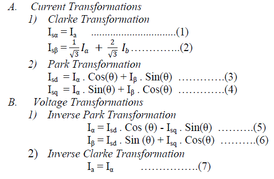 |
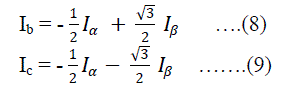 |
| One can generate any voltage vector laying inside the hexagon whose corners on the six active switching state vectors (V1-V6)
in space vector modulation strategy, the inverter out net reference vector Vref can be approximated during a sampling time Δt =
1/(2fs) by a sequence of 3 space voltage vectors Va, Vb and VN, where Va and Vb are 2 of the adjacent six active vector V1....V6
VN is a zero vector Vo and V7 chosen in such a way to minimize the commutations in the inverter fs is the switching frequency. |
| Vref is defined as, |
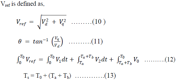 |
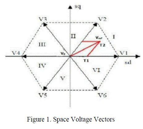 |
SIMULATION RESULTS |
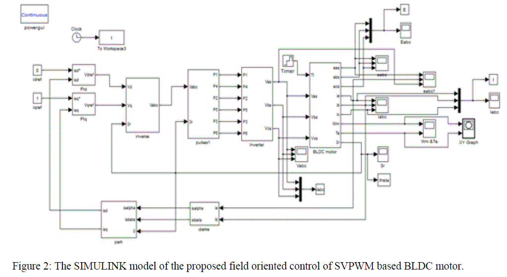
| The proposed technique was developed and simulated in MATLAB/SIMULINK software. The Simulink model is shown in
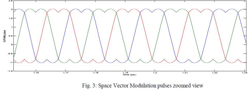
Figure 2. The results of various parameters were taken as different load torques. The zoomed view of the SVPWM pulses were
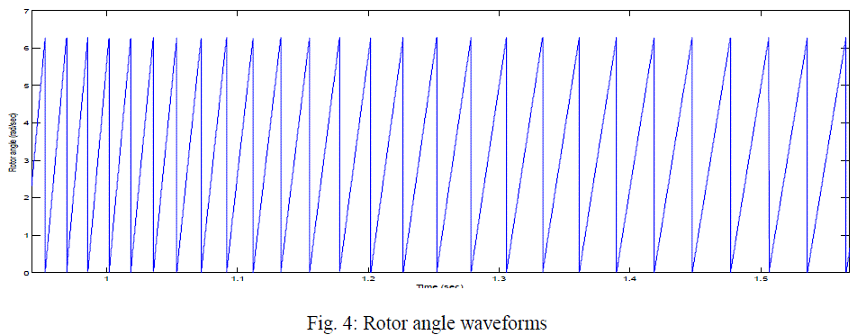
is shown in Figure 3. The inverter input voltage is set at 24V. The waveform of rotor angle is shown in Figure 4. |
 |
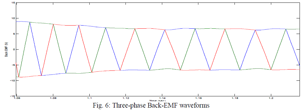
| The obtained waveforms of three phase Back EMF waveforms of BLDC motor are shown in Figure 6. The maximum Back –
EMF at no-load is 20V and as the load increases the Back-EMF decreases. The three phase waveforms of the BLDC motor
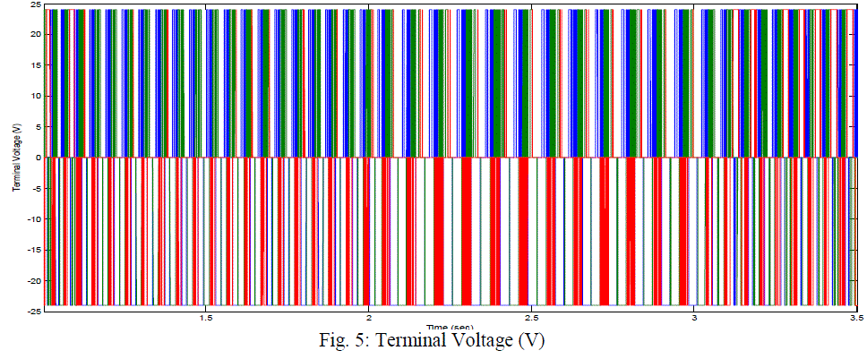
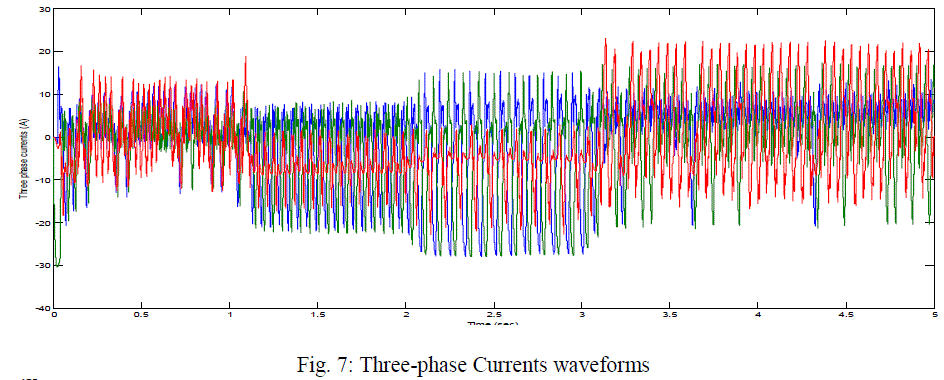
currents are shown in Figure 7. The maximum current at 2 N-m load torque is 18A. The terminal voltage waveform of BLDC
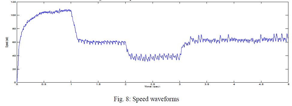
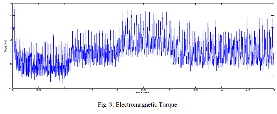
motor was also shown in Figure 5. The speed waveform of the motor is shown in Figure 8 and the torque waveform is shown in
Figure 9. We can observe that the torque ripple is reduced in the case of closed loop control of BLDC motor using SVPWM.
The parameters of the BLDC motor are given in Table 2. |
 |
 |
 |
 |
 |
 |
 |
 |
CONCLUSIONS |
| In this paper, fuzzy PI controller for BLDC motor considering variable sampling time was proposed. Three
fuzzy logic controllers to scale speed error for the three PI controllers were used in this paper. Three subsystems for
various sampling simulation have been presented. First is the continuous time model of BLDC motor, the second is
the variable sampling time and the third is the discrete time speed and variable sampling time constant estimator.
The results have been presented and analyzed for different speed conditions. |
References |
- K.NagaSujatha, Dr. K.Vaisakh and Anand. G „Artificial Intelligence based speed control of brushless DC motor‟ IEEE 978-1-4244-6551-4/10 2010.
- „AN885 - Brushless DC (BLDC) Motor Fundamentals‟ 2003 Microchip Technology Inc.
- Cheng-Tsung Lin, Chung-Wen Hung and Chih-Wen Liu „Fuzzy PI controller for BLDC motors considering Variable Sampling Effect‟ IEEE Industrial Electronics Society (IECON) Nov. 5-8, 2007, Taipei, Taiwan.
- P.Pillay and R.krishnan. „Modelling, simulation and analysis of a Permanent magnet brushless Dc motor drive‟ IEEE trans. Ind Applicant., Vol26, pp124- 129, 2002.
- „Clarke & Park Transforms on TMS320C2XX‟ An Applicatio Report by Texas Instruments.
- „Sensorless Field Oriented Control of PMSM Motors‟ AN1078 by Microchip.
- Joseph P John, Dr. S. Suresh kumar and Jaya. B „Space Vector Modulation based Oriented Control Scheme for Brushless DC Motors‟ Proceedings of ICETECT 2011.
- „Field Orientated Control of 3-Phase AC-Motors‟ Literature Number: BPRA073, Texas Instruments Europe, February 1998.
- Ji Hun, Li Zhiyong „Simulation of Sensorless Permanent magnetic brushless DC motor control System‟ Proceedings of IEEE International conference on automation and logistics Quigdao, China September 2008.
|