This paper deals with the vector control of a Permanent Magnet Synchronous motor (PMSM) employing Sinusoidal Pulse Width Modulation. These motors are becoming increasingly popular in industrial applications due to their high-efficiency, fast dynamic response and compact size. Until recently, programming and implementation costs of high-performance control algorithms for these motors have been prohibitive. However, great strides have been made by hardware manufacturers such as Microchip, Freescale, IRetc to facilitate these algorithms in the architecture of their processors. This has brought down the development costs significantly and opened up whole new avenues for PMSM. The paper details a drive system which utilizes a DSP to implement Field Oriented Control (FOC) of the motor. The mathematical model of a PMSM is discussed and a Simulink model of the entire drive system is illustrated. Simulation runs are conducted for different working conditions and compared with the practical results.
Keywords |
| PMSM, Permanent Magnet Synnhronous Motor, Pulse Width Modulation (PWM), Field Oriented
Control (FoC), PI Controller, Simulink, Digital Signal Processor (DSP) |
INTRODUCTION |
| Electric Drives play a pivotal role in every Industry. Each industry has its own specific requirements and operating
conditions. The designer of a drive system must choose the motor and control strategy appropriately so that all the
requirements are satisfied while at the same time keeping the expenditure as low as possible. Drive systems can either
be classified as constant-speed or variable-speed drives. Traditionally, A.C machines which operate on a fixed
frequency sinusoidal supply are employed in Constant-speed drives, while D.C machines are preferred for variablespeed
drives. However, the presence of commutators and brushes in D.C motors leads to maintenance issues, increased
losses due to sparking, higher motor inertia and generally higher costs. A Permanent Magnet Synchnronous Motor
(PMSM) can be used to overcome many of the drawbacks of conventional D.C motors due to the innate nature of its
construction. |
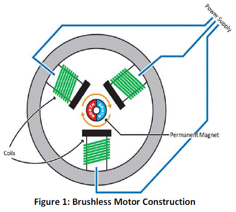 |
| In its simplest form, a PMSM consists of a Permanent Magnet which acts as the rotor as opposed to conventional
rotor windings. The rotor is surrounded by three equally spaced fixed stator windings as shown in Figure 1. The current
flow in each winding produces a magnetic field vector which sums up to form a resultant magnetic field. Torque is
produced in the motor by the attraction or repulsion between this net stator magnetic field and the magnetic field
produced by the permanent magnet, i.e. rotor. By controlling the current flow in the three windings, a magnetic field of
arbitrary direction and magnitude can be produced by the stator and thereby, the torque produced can be controlled. |
| Conventional Brushed motors are commutated mechanically by means of brushes in contact with the commutator
which switch the current when the motor moves. Brushless motors however, lack any form of brushes and commutator.
They are instead commutated by using power electronic switching circuits. Due to this, these types of motors are able
to offer numerous advantages over conventional brushed motors [2]. They are: |
| • Brushless construction does not produce any sparking and eliminates the need for brush maintenance. |
| • Since there are no field windings, there are no field copper losses resulting in improved efficiency. |
| • They are able to maintain a constant speed throughout the operation. |
| • A Permanent Magnet Motor is smaller in size than an induction motor of the same capacity. |
| • Has lower rotor inertia when compared to Induction Motors because of the absence of a rotor cage. This allows
for faster response. |
| The only drawback of these Permanent magnet motors is that the algorithms and electronics required to control
the current in the motor are somewhat complex. |
COMPARISON OF PMSM AND BLDC MOTORS |
| There are primarily two main types of Brushless motors, namely- The Brushless DC Motor (BLDC), and the
Permanent Magnet Synchronous motor (PMSM). They both share the same basic construction, consisting of permanent
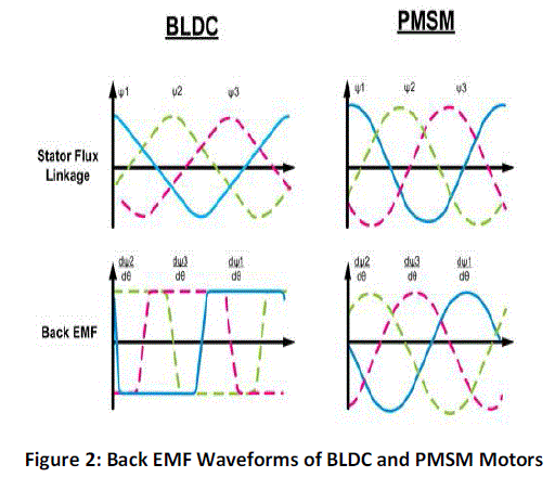
magnets on the rotor and windings on the stator. However, one principal difference is that the coils in the stator are
evenly wound in a BLDC motor, and in the case of PMSM they are wound in a symmetrical fashion. As a result, the
Back-EMF generated in a BLDC motor is trapezoidal in nature as shown in Figure 2, and Sinusoidal in nature in
PMSM motors. Consequently, the PMSM motors are more efficient and produce less noise and torque ripple. However,
the inherent advantages of a PMSM motors does necessitate more complex control algorithms. |
 |
OBJECTIVES OF A CONTROL STRATEGY |
| For any position of the rotor, there is an optimal direction for the net stator field which maximizes the torque
produced [1]. If the net stator field and the rotor field are in the same direction then no torque will be produced. This is
because the forces produced by the interaction of the fields act in line with the axis of rotation of the rotor and only
leads to compression of the motor bearings, rather than rotation. If the stator field is perpendicular to the rotor field,
then maximum torque is produced. |
| Any stator field can be represented as a resultant of two vector components, the orthogonal (quadrature) component
which is responsible for producing torque, and the parallel (direct) component which produces undesired heat and
compression forces. Hence, an ideal drive should aim to minimize the parallel component while maximizing the
quadrature component. |
| The stator field is produced by current flow in three equally spaced windings that are mechanically located 120o
apart. Hence, they each produce a field vector component that is oriented 120o from each other. The mathematical
models for Permanent Magnet Motors are in terms of winding currents rather than stator magnetic field since they are
easier to measure. Current Space Vectors are used to model the stator fields in terms of winding currents. The current
space vector for a given winding has a magnitude proportional to the current flowing through the winding and a
direction of the field produced by that winding. This allows us to represent the total stator field as a current space
vector that is the vector sum of three current space vector components of the windings. To put this simply, the resultant
current space vector is the current that would need to flow in a single fictitious winding in order to produce the same
stator field direction and magnitude as the combination of three real currents through real stator windings. |
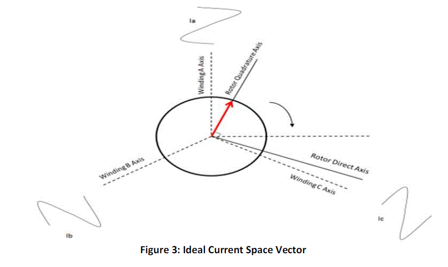
| Just like the stator field, the current space vector too can be broken down into quadrature and direct axis
components. The orthogonal (quadrature) current component produces a field at right angles to the rotor magnet and
therefore results in torque, while the parallel (direct) current component produces a field that is aligned with the rotor
magnet and produces no torque. Hence, the aim of a control algorithm is to reduce the direct current components so as
to minimize losses. The Current Space Vector is illustrated in Figure 3, where the three windings are named A,B& C. |
| To produce constant smooth torque, the stator current space vector should ideally be constant in magnitude and
should turn with the rotor so as to always be in the quadrature direction, irrespective of rotor angle and speed. To
achieve this, various control algorithms have been experimented and developed with varying degrees of success. |
 |
FIELD ORIENTED CONTROL |
| The most prevalent control strategies for Brushless motors are Trapezoidal Control, Sinusoidal Control and
Field Oriented Control, each with their own share of advantages and drawbacks. Trapezoidal Control is relatively
simple and offers smooth operation at high speed but causes torque ripple at low speeds. Sinusoidal Control eliminates
torque ripple and provides efficient operation at low speeds but the limitations of a PI controller make it unsuitable for
high speed applications. Field Oriented Control (FOC) combines the best aspects of the previous two methods, offering
smooth and efficient operation with fast dynamic response at both low and high speeds. Due to this reason, we have
opted to implement FOC in our drive system. |
| The Field Oriented Control algorithm shares lot of common ground with Sinusoidal Control. However, some
fundamental differences allow it to achieve better efficiency at high speeds. The main drawback of Sinusoidal Control
arises due to the fact that this control scheme tries to control the motor currents whose magnitude and direction varies
with time. As the speed and frequency increase, the PI controllers are incapable of handling the operation due to their
limited bandwidth. This problem can be overcome by representing and controlling the current space vector in the two
axis d-q frame of reference. |
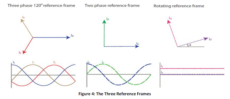
| This control scheme revolves around Clarke and Park Transformations, and their inverse. By applying these
transformations, we can transform the 3Φ currents of the stator into the rotating frame of the rotor. |
| By using Clarke Transformation, three-phase quantities are translated from the three-phase reference frame to the
two-axis orthogonal stationary reference. However, the quantities are still in a stationary reference frame while the
rotor reference frame is constantly rotating. Park’s Transformation converts these quantities into an orthogonal
reference frame consisting of the direct and quadrature axis. The three reference frames are illustrated in Figure 4. |
 |
| The combined Clarke and Park Transformations can be written in Matrix form as: |
 |
 |
 |
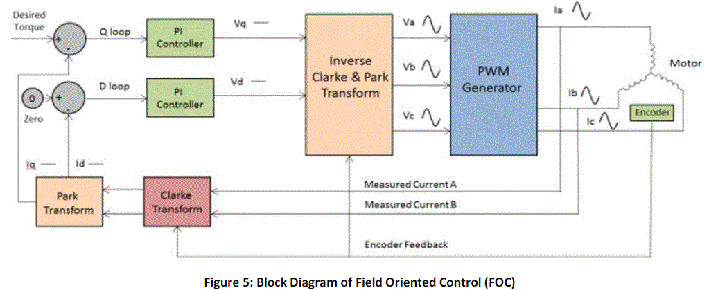
| As mentioned earlier in section III, the direct axis component produces useless torque while the quadrature
axis component produces the torque responsible for rotation. In an ideal case, the current space vector in the d-q frame
is fixed in magnitude and direction (quadrature) with respect to the rotor, irrespective of rotation. Since the current
space vector in the d-q frame of reference is static, the PI controllers now have to operate on DC quantities rather than
sinusoidal signals, thus greatly simplifying the control structure. This isolates the controllers from the time variant
winding currents and voltages, therefore eliminating the limitation of controller frequency response and phase shift on
motor torque and speed. The block diagram for a standard FOC drive is shown in Figure 5. |
| By isolating the PI controllers from the time varying currents and voltages, the FOC algorithm is able to offer
numerous advantages, such as: |
| • High Efficiency |
| • Smooth operation at low and high speeds resulting in a wide range of speed |
| • Transformation of a complex and coupled AC model into a simple linear system |
| • Fast dynamic response and good transient and steady state performance |
| The only limitation which held back the adoption of FOC was that the transformations that needed to be processed
requires a lot of computation power and was difficult to implement. These days, microprocessors and DSPs with
Vector Control features implemented into the architecture itself are readily available in the market. This has led to a
surge in the utilization of Brushless motors thanks to effective control strategies delivering high efficiency and meeting
numerous requirements. |
| There are several techniques that can be used to generate the gating pulses (i.e pulse width modulated pulses) for
the inverter circuit in FOC, the most notable ones being Sinusoidal PWM, Space Vector PWM and Third Harmonic
Injection PWM. Soft Computing Techniques such as Fuzzy Logic, Genetic Algorithms, Neural Networks etc can also
be used to implemented in applications which require the utmost accuracy [8]. |
OVERVIEW OF DRIVE SYSTEM |
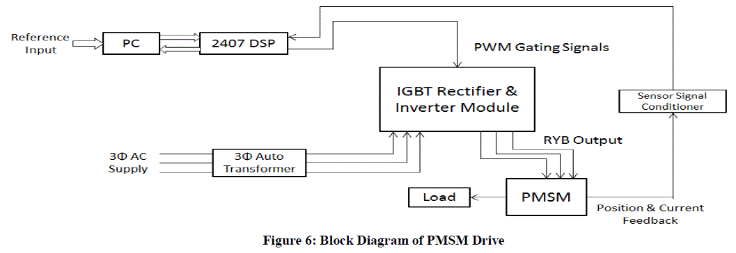
| With the aim of delivering good dynamic response for a wide range of speed, a drive system was developed which
utilizes a 16-bit Digital Signal Processor (DSP) and an IGBT module to implement Field Oriented Control using
Sinusoidal PWM (sPWM) [5]. The schematic diagram of the system is as shown in Figure 6. |
| The various functional units of the system are as follows: |
| • Permanent Magnet Synchronous Motor (PMSM): The motor chosen for the drive system is a 800W, 2.55 Nm
Permanent Magnet Synchronous Motor (PMSM) manufactured by the company Motor Power. |
 |
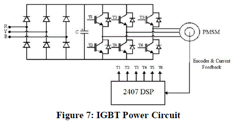
| • IGBT Power Module: The IGBT module controls the power flow to the motor. The 3Φ input to the module is first
rectified into the DC link voltage through a bridge rectifier circuit, which is in turn converted to a variable AC supply
by the IGBT bridge which behaves as an inverter. The IGBTs are triggered by PWM pulses which are generated by the
DSP after processing the signals received from the speed sensor. Hence, the voltage supply to the machine can be
controlled by varying the duty cycle of the triggering pulse. This regulated AC supply acts as the power input to the
motor. The IGBT power circuit is illustrated in Figure 7. |
 |
| • 16-Bit Digital Signal Processor (DSP): A digital signal processor (DSP) is a specialized microprocessor whose
architecture is specifically designed for digital signal processing. Although most general-purpose microprocessors can
execute DSP algorithms, they are not suitable for most applications due to power and space constraints. A specialized
DSP can provide a lower-cost solution, with better performance and lower latency. |
| •
In our case, we have opted for a TMS320LF2407A DSP from Texas Instruments. The DSP Core is interfaced
with external peripherals and memory. However, the DSP core itself is able to generate up to 12 PWM Pulses without
the aid of any external peripherals thanks to the integrated Event Manager (EV) module. |
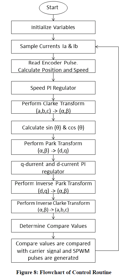
| The role of the DSP in this system is to act as a PI controller and generate the gating pulses for the IGBT
circuit to ensure that the motor operates as desired. The speed and current values of the motor are fed back to the DSP
for the purpose of Closed Loop Control. The DSP is to be programmed such that it performs Clarke and Park transform
on the 3Φ quantities and determines the required duty cycle of the PWM signals taken in order to align the current
vector in the quadrature direction. The flowchart of the control algorithm is shown in Figure 8. |
| • Sensors: A Quadrature Encoder Pulse (QEP) sensor feedback is used to deduce speed and position information from
the motor. The PMSM motor encoder section generates 2000 pulses per revolution. By monitoring these pulses, the speed and position can be computed. Two motor phase currents are measured using a current sensor. The third phase is
the negative sum of the first two. This information is used by the DSP to transform the signals into the d,q rotating
reference frame generate the appropriate control signals. |
 |
| • PC: The PC’s function is to provide a simple interface between the user and the system. It forms the basis of
interaction between different components of the system. The Reference input (i.e required speed) is inputted via the PC
and then transmitted to the DSP. It is also used to monitor the motor’s speed by plotting the actual speed along with
reference speed during motor operation. The interface and the interaction between the PC and the DSP were designed
using Visual basic. |
| • 3Φ auto transformer: An auto transformer is used to regulate the 3Φ AC supply input to the IGBT module. |
MATHEMETICAL MODEL OF PMSM |
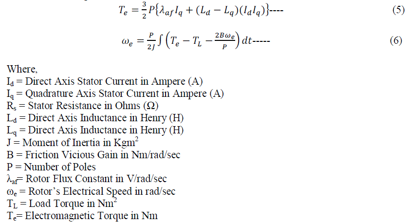
| The electrical and mechanical equations of the PMSM in the rotor (dq) reference frame are as follows: |
 |
| By rearranging the terms in Equation (1) & (2), and then integrating them, we can obtain the equations for direct axis
and quadrature axis currents. |
 |
| The mechanical equations can be written as |
 |
SIMULINK IMPLEMENTATION |
| The drive system described is modelled in Simulink and is shown in figure 9. |
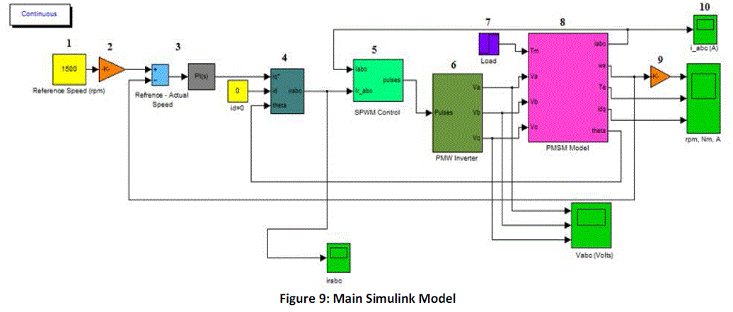 |
| The functions of each of the labelled blocks are as follows: |
| 1) Reference Speed: The required speed is set in rpm using a Constant block. |
| 2) The electrical and mechanical equations of a PMSM requires speed to be represented in the form of radians/sec. The
Speed set by the user is in rpm and can be converted to radians/sec by multiplying it with 2×π
/16 (i.e gain block) |
| 3) PI Control Block: The Error Signal is obtained by subtracting the Reference Speed with the Actual Speed. For the
PI control, Matlab’s default control is used. The values of P and I parameters are obtained as follows: |
 |
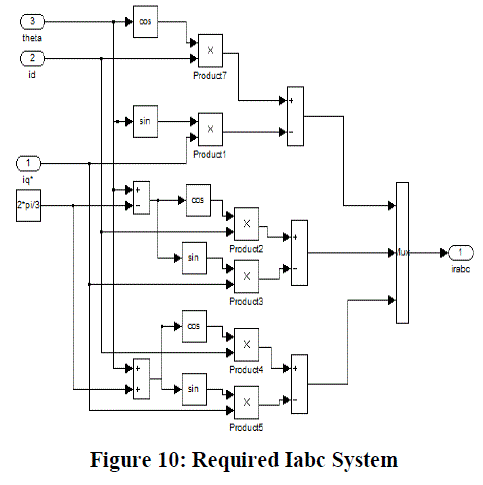
| 4) Required Ia,b,c Subsystem: The inputs to this subsystem are the required values of Direct Axis (Id), Quadrature Axis
(Iq) Current, and the real time value of theta (θ) which is fed back . As mentioned in Section III, the direct axis
component of Stator Current produces useless compression forces. Ideally, we would prefer if the direct axis
component is 0. Hence, we have set the required value of Id to a constant 0. |
| This subsystem essentially computes the required values of the three phase currents, by performing inverse Clarke and
Park Transformation (as described in Section IV ) on the direct axis and quadrature axis currents. Underneath the mask,
are the blocks as shown below: |
 |
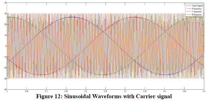
| 5) Sinusoidal PWM Block: This subsystem generates the six PWM waveforms for the IGBT bridge circuit. The blocks
underneath the mask are shown below: |
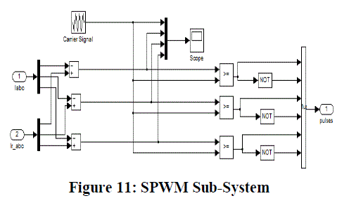 |
| The Carrier Signal is basically a triangular waveform generated by a repeating sequence which is configured as
follows: |
| Time Values: [0 1/(4*fs) 3/(4*fs) 1/fs] |
| Output Values:[0 –V +V 0] |
| Where fs = Switching frequency of the Inverter; |
| V= DC Link Voltage the IGBT bridge |
 |
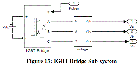
| 6) IGBT Bridge Circuit: The three arm, 6-IGBT Inverter Circuit is implemented by using the Universal Bridge
provided by SimPowerSystems. The Gating Pulses (PWM) is provided by the Sinusoidal PWM Control Subsystem. |
 |
| 7) Load: In this model, the load is modelled as a step signal whose value is in Torque (Nm). This Load Torque is used
in the main motor subsystem to compute other quantities. |
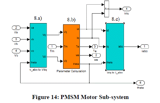
| 8) PMSM Subsystem: This subsystem implements the mathematical model of a PMSM as detailed in Section VI. In
addition to the Va, Vband Vc waveforms from the inverter model and the load torque, several other parameters are
defined in the mask of the subsystem. These parameters are constants which pertain to the specification of the motor.
The parameters defined in this way are: |
| R = Stator Resistance in Ohm (Ω) |
| Ld = Direct Axis Inductance in Henry (H) |
| Lh = Quadrature Axis Inductance in Henry (H) |
| Yaf = Rotor Flux Constant (V/rad/s) |
| J = Moment of Inertia (Kgm2) |
| B = Friction Vicious Gain (Nm/rad/sec) |
| P = Number of Poles |
 |
| The block is further classified into different sub systems as detailed below: |
| 8.a) Vabc to VdqSubsytem: This subsystem transforms the 3Φ voltage quantities from a three-axis stationary frame to a
direct-quadrature axis rotating frame by using Clarke and Park Transformation. |
| 8.b) PMSM Parameter Calculations: This subsystem carries out all the calculations to obtain the real time parameters of
the motor, such as: Direct Axis Current, Quadrature Axis Current, Electromagnetic Torque, Speed and rotor position
(θ). It’s further grouped into three other subsystems as shown in Figure 15. |
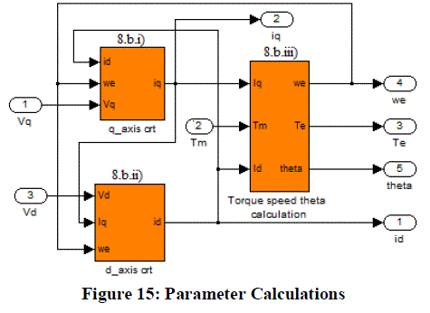 |
| Each subsystem essentially implements the electrical and mechanical equations detailed in Section VI using standard
Simulink blocks. |
| 8.c)Idq to IabcSubsytem: The Current values obtained from the PMSM subsystem are in the direct-quadrature axis
reference frame. In order to feedback these values, we need to transform it back to the 3Φ reference frame. This
subsystem is essentially the same as the one detailed in the Required Ia,b,c Subsystem in Part 4). |
| 9) The speed computed by the PMSM model block is in radians/sec. However, for the sake of user convenience, it is
converted to Rotations Per Minute(rpm). The conversion is performed by setting the gain block to 60/
2*π |
| 10) Scope Blocks are used to observe the various waveforms in real time. |
RESULTS |
| Simulation Runs have been carried out for various load cases. Here, we present two cases, one where the motor is
started on load which remains constant throughout the operation, and another where the load applied is increased after
some time has elapsed. |
| Case 1: The reference speed is set to 1500 RPM and a load of 3 Nm is applied from the start. The observed phase
current waveforms are shown in Figure 16. |
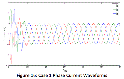 |
| The initial current overshoots due to the high starting torque, but soon settles to uniform sinusoidal waveforms
within 0.06 seconds. We can also observe that each waveform is displaced 120o from each other. |
| The Speed, Torque, Direct Axis and Quadrature Axis current waveforms are shown in Figure 17. |
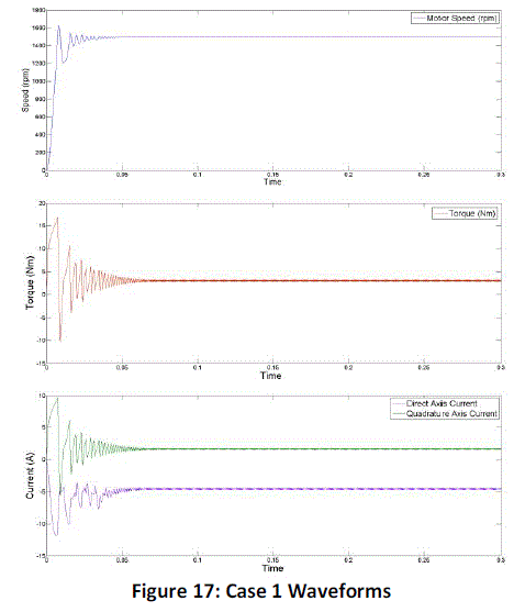 |
| The speed overshoots to around 1610 rpm at start and oscillates slightly, but soon settles to 1494 rpm and remains
stable. Naturally, the starting torque is high but settles to its rated value within 0.13 seconds. |
| Case 2: The reference speed is set to 1500 rpm and a load torque of 3 Nm is applied at start. The load is then increased
to 5 Nm at t=0.1secs. The phase currents are as shown in Figure 18. |
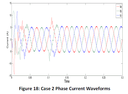 |
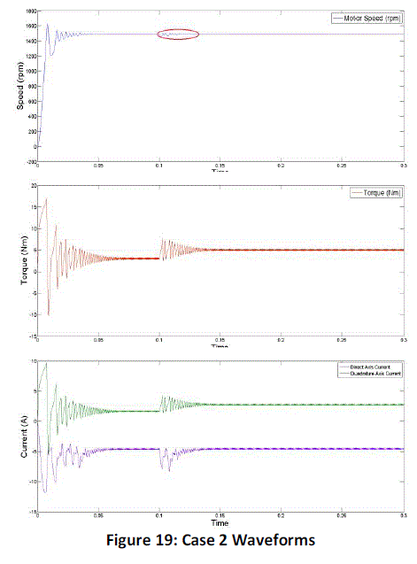
| When the load is increased at t=0.1 secs, the speed drops to a value of 1460 rpm, and hovers between 1460
and 1510 rpm (highlighted by the red circle in the Figure 19) and the phase current amplitude also increases after a
small transition period. But within t=0.13 secs, the controller action brings the speed back to the reference speed of
1500 rpm. The torque produced by the motor also increases to counterbalance the load torque applied to it, which
causes a corresponding increase in direct axis and quadrature axis currents as well. |
 |
Practical Results |
| The practical implementation was tested with various load cases and the results obtained for a few scenarios
are presented here: |
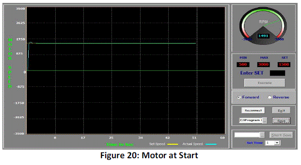 |
| With a set speed of 1500 rpm and a load of 3 Nm, the motor reaches its set speed with only a slight overshoot as
shown in Figure 20. |
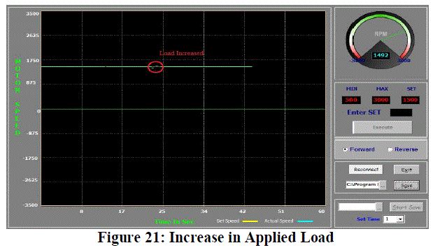 |
| When the load is increased to about 5 Nm, the motor undergoes a minor transient period which lasts for about a
second, as highlighted by the red circle in Figure 21, after which it settles at a steady state. |
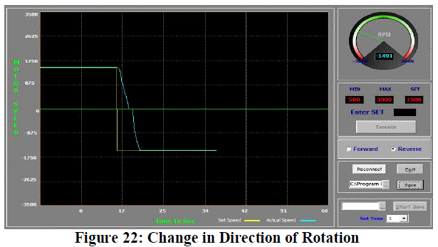 |
| The system is designed such that the direction of rotation can be changed conveniently in the interface. In Figure
22, the motor direction is reversed. As a result of the inertia due to rotation in the forward direction, the direction
cannot change immediately and some time is required for the motor to first come to rest and then reverse the direction. |
CONCLUSION |
| PMSM motors are garnering more and more attention over time and the development of new and efficient control
algorithms will further enforce them as a superior and financially viable substitute to traditional Induction motors.
The PMSM drive system utilizing Field Oriented Control (FOC) has yielded satisfactory performance in both
simulation and practical implementation, with minor variation in Speed and Torque as evident in the results. The DSP’s
Instruction Set Architecture (ISA) and its integrated peripherals have simplified the development of software and
hardware. The real time processing capability of the DSP allows for a highly reliable drive which is able to operate
efficiently under a wide range of speeds, and also offers the potentiality of implementing more advanced or complex
control schemes high-performance variable speed drives. Further improvements can be realized by incorporating Space
Vector PWM (SVPWM) instead of the conventional Sinusoidal PWM (SPWM) [11]. It is also possible to implement
soft computing techniques for the control algorithm although this would require sufficient knowledge to develop the
hardware. It is up to the designer to choose the most optimal and viable control strategy to meet all his requirements. |
References |
- R. Krishnan, Electric Motor Drives Modeling, Analysis and Control, Prentice Hall 2001.
- Pragasen P, Ramu Krishnan, âÃâ¬ÃÅ Application Characteristics of Permanent Magnet Synchronous and Brushless DC Motors for Servo DrivesâÃâ¬ÃÂ, IEEE Transactions on Industry applications. Volume 27, No. 5, 1991: 986-996.Magn. 2007; 43(1): 438-442.
- PingHua Zhang, GuiJie Yang, TieCai Li: âÃâ¬ÃÅStudy on the Vector Control Method ofIMfor Variable Speed Drive Based on DSPâÃâ¬ÃÂ, Proceedings of the 2006 IEEE/RSJ International Conference on Intelligent Robots and Systems October 9 - 15, 2006, Beijing, China
- Fodor, D.; Katona, Z.; Szesztay, E.; "Digitized vector control of induction motor with DSP", Industrial Electronics, Control and Instrumentation 1994. IECON '94., 20th International Conference on Volume 3, 5-9 Sept.1994 Page(s):2057 âÃâ¬Ãâ 2062 vol.3.
- âÃâ¬ÃÅVector Control of 3-Phase AC-MotorsâÃâ¬Ã Texas Instruments
- Bimal K. Bose, Modern Power Electronics and AC Drivers, Prentice Hall, 2002.
- Pragasen P, Ramu K, âÃâ¬ÃÅControl Characteristics and Speed Controller Design for a High-Performance Permanent Magnet Synchronous Motor DriveâÃâ¬ÃÂ, IEEE Transactions on Power Electronics. Volume 5, No .2,1991: 151-158.
- A.Accetta, M.Cirrincione, M.Pucci,âÃâ¬ÃÂTLS EXIN based neural sensorless control of a high dynamic PMSMâÃâ¬ÃÂ, Control Engineering Practice, vol.20, issue.7, pp.725-732, July 2012.
- Son, Y.-C, Bon-HoBae, Seung-Ki Sul, âÃâ¬ÃÅSensorless operation of permanent magnet motor using direct voltage sensing circuitâÃâ¬ÃÂ, 37th IAS Annual Meeting.Conference on Industry Applications, 2002.
- P. Pillay and R. Krishnan.,âÃâ¬ÃÂModeling of permanent magnet motor drivesâÃâ¬ÃÂ, Industrial Electronics, IEEE Transactions on, Vol. 35, 537-541, 1988.
- DrazenDujic, , Gabriele Grandi, Martin Jones, and Emil Levi, âÃâ¬ÃÅA Space Vector PWM Scheme for Multi frequency Output Voltage Generation With Multiphase Voltage-Source InvertersâÃâ¬Ã IEEE transactions on induction motor, VOL. 55, NO. 5, MAY 2008
|