This paper presents control methods for controlling two independent loads simultaneously by using five-leg ZSource Inverter and High-Performance Z-Source Inverter. In recent years, five-leg inverter has been proposed. This inverter can control two three-phase loads independently at a time, this inverter has five legs,each leg consists of two switching devices and total ten switching devices. AandB phases of both loads are connected in each leg respectively whereas C phase of both loads is connected in common leg. In five-leg inverter, C phase of the loads are connected in the common leg, it causes difference from a switching pattern of C phase in two loads. For this reason, the modulation methods of a three leg inverter can’t be used for the fiveleg inverter. Many modulation methods for the five-leg inverter have been proposed, but Voltage Utility Factor is 50% in these methods. This paper proposes a novel structure for Z-source five-leg inverter. First, the construction of five-leg inverter, Z-source five-leg inverter is introduced and then PWM modulation methods for the Z-source five-leg inverter are elaborated. Consequently, it is shown with Z-source one can improve Voltage Utility Factor in five-leg inverter. In the end, the validity of the method is verified by simulations
Keywords |
| Five-Leg Inverter (FLI); Z-source FLI; High Performance Z-source FLI;PWM techniques |
INTRODUCTION |
| In electric trains, electric vehicles and some other industry applications, multiple drivesystem is needed, inwhich two or
more loadsoperate in parallel. Generallyin multiple drive system, one voltage source inverter (VSI)is needed to feed
one three phase load. Therefore, a largenumber of power electronic devices are required, whichmeans a complex
structure and high cost. In recent years, alot of researches have beenconducted to reduce the numberof switches. Due
to wide spread uses of three-phase loads in industrial applications, control of these loads are a very important thing. In
many cases two or many loads need to be controlled independently. Traditionally, often two methods are employed for
controlling two three-phase loads. The first method is the use of two inverters separately for each of the loads. This
method needs twelve semiconductor Switches to control the loadsresulting in higher cost and more complexity for the
control systems. The second method is the use ofonly one inverter for two loads.In this manner, two loads are
connected in parallel with a single inverter andthereis no independent control over each of the loads. The above two
methods have some disadvantages i.e.,in firstmethod the space requirement is more, high switchinglosses etc., In
second method if fault occurred on any one load total system is completely shut down. The human beings are always
looking for ways to control the loadswith minimum cost, maximum efficiency and minimum dimensions of the control
system. To improve and simplify the control system, five-leg inverter (FLI) has been proposed [1, 5]. FLI is a single
inverter that can drive two loads independently. For FLI the PWM techniques used for three-phase or three-leg inverter
should not be applied since in FLI inverter one leg is common for both loads. In FLI, since the DC voltage source is
shared between the two loads, the voltage across each load is less in the case of a three-leg inverter. In the previous
papers different PWM methods Dual voltage modulation, Inverse table method, Modulation block method, two arm
modulation method, Double zero sequence injection method etc., are proposed in these methods the voltage utility
factor is less than 50% and also control two loads independently at a time is not possible. Therefore, a larger DC
voltage source is needed in this method which increases systemcost and size. In this paper this is improved by using Zsourcestructure.
In this paper in first section, structure of proposed Z-sourceInverter is expressed. In second section, the
PWMmethods for Z-source FLI are illustrated. In third section,structure of the high performance Z-source in FLI
forimproving the Voltage stability is described. In fourth section,simulations are performed to verify the validity of the
statements. |
ARRANGEMENT OF THE FIVE-LEG INVERTER |
| Fig. 1 shows the structure of the FLI. This inverter consists of five legs; each leg consists of two series switches and in
the total of 10 semiconductor switches.As can be seen in Fig. 1, C-phase of two loads is connected in a common leg
while the other two phases are connected in separate legs. Pulses for this inverter are generated with PWM method;
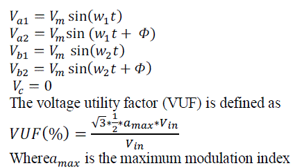
reference signal for each leg is given by (1).In (1) a reference signal to C-phase is zero. This implies that the signal can
be considered zero for the common leg in this inverter. In this manner, the Voltage Utility Factor (VUF) for each load
can be calculated to be 86.6% which means that the maximum voltage for each load is 86.6% of the DC voltage link.
This requires a larger source. |
 |
 |
| In the functioning of switches, value 1 for switch is in ON state and value 0 for switch is in OFF state are considered. |
| If S refers to switches: |
 |
| The switching restriction in (3) prevents short-circuiting in DC voltage source. |
ARRANGEMENT OF THE Z-SOURCE FIVE- LEG INVERTER |
| To improve output voltage for each load, Z-source FLI is proposed. In this inverter Z-network is placed between the
FLI and a DC voltage source. By controlling the shoot-through duty ratio of the short circuit mode, this inverter is able
to produce any AC voltage in its output. When a rectifier is used as the input, Z-source FLI can reduce current
harmonics, improve reliability and increase output voltage range. In this paper, two different structures, normal Zsource
and high performance Z-source in FLI are studied. Structure of the normal Z-source is shown in Figure2. |
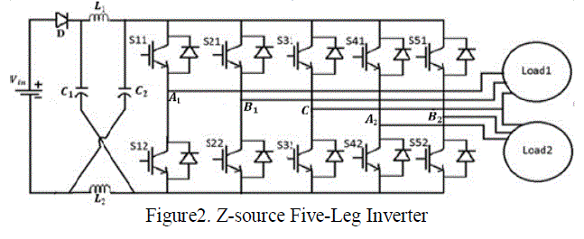 |
| In this architecture, the Z-network is used to connect the DC source and the FLI. The DC source can be a battery, a
diode rectifier or a Thyristor converter. For the traditional VSI, both switches of any phase leg cannot be gated on
simultaneously otherwise a short circuit (shoot through) would occur and destroy the circuit. But in Z-source inverter,
by switching ON the two switches in one leg, the DC voltage can be boosted while the shoot-through state can no
longer destroy the inverter. In this method, the switching frequency viewed from the Z-source network is ten times the
switching frequency of the main inverter, which greatly reduces the required inductance of the Z-source network. The
Z-source network is assumed to be symmetrical network by assuming that the inductors and capacitors have same
value.This will reduce the complexity of calculations.With assuming that the T0 is shoot-through time and T is duty
cycle,thepeak dc-link voltage across the five leg inverter bridgecan be written as: |
 |
 |
| Equation (7) shows that by changing the boost factor the output voltage of each load can be changed. Boost factor (B)
can be controlled by controlling the duty cycle of short circuit mode. The shoot through state does not affect the PWM
control of the five leg inverter, because this state produces the same zero voltage to the load terminal. The available
shoot through period is controlled by adjusting the modulation index(M). |
MODULATION OF THE Z-SOURCE FIVE-LEG INVERTER |
| In the before section as we discussed, Z-source FLI utilizes short circuit state or shoot-through state to boost DC link
voltage, whereas the conventional five leg inverters do not allow the use of shoot-through state. Therefore, the
traditional control methods used for regular five leg inverters should be changed. In this section, three PWM methods
for controlling Z-source five leg inverters are explained. These methods include simple-boost PWM, maximum-boost
PWM and constant-boost PWM. |
| 1. Simple-Boost PWM of the Z-source Five-Leg Inverter: |
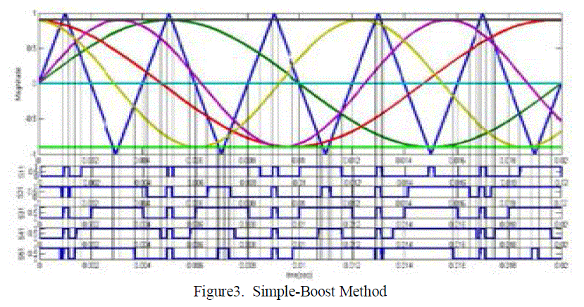
| In conventional PWM method, four line signals and one zero signal are produced as the reference signals. In Simpleboost
PWM methods, like the conventional PWM, the switching signals are generated by comparing five reference
waves with the carrier wave. The only difference is that for Z-source inverter modulation this method utilizes two dc
signals V1 and V2for providing short circuit states. These dc signals are equal to or greater than the maximum value of
the sinusoidal reference signals. Whena triangular high frequency carrier signal is greater than V1 oris smaller thanV2,
all switches are turned off and the circuitturns into shoot-through state as illustrated in Fig. 3. In this method, boost
factor can be written as: |
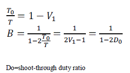 |
| From this equation it is observed that by decreasing V1 , the value of B can be increased. However, it should be noted
that V1 cannot be smaller than M otherwise it would interfere with a reference wave and convert an active vector to a
zero vector. |
 |
| 2. Maximum-Boost PWM of the Z-source Five-Leg Inverter: |
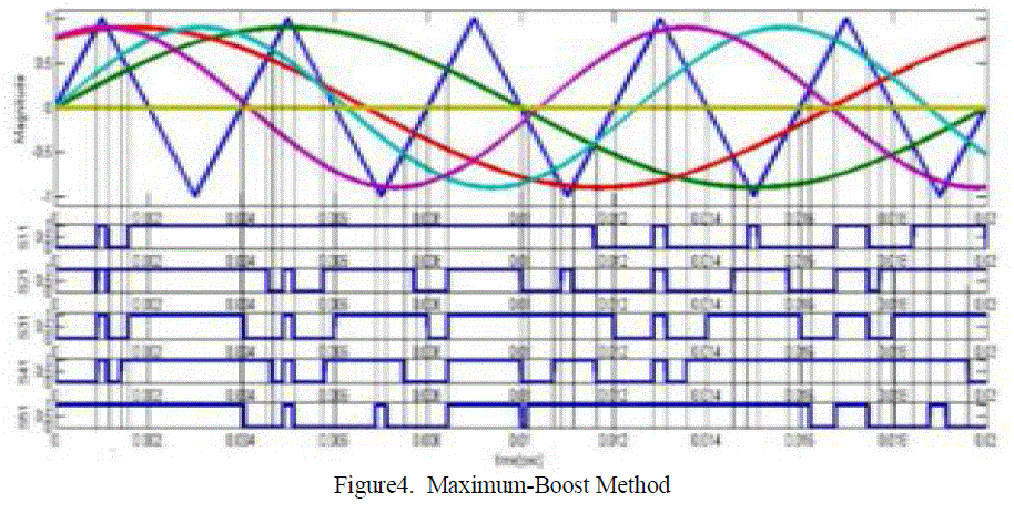
| To use the maximum possible short circuit states, another modulation method can be used which is called maximumboost
PWM method [7]. Like in normal PWM method when the triangular carrier wave is greater than the maximum
value of the sinusoidal references or smaller than the minimum value of the sinusoidal references, all switches are
turned into active state. There arefive references among these with only four sinusoidal reference signals, short
circuittime is determined. As can be seen in Fig. 4,therefore, the shoot through duty cycle varies in each cycle. This
increases voltage ripple and in some cases may result in voltageinstability. In this method, except for the zero
reference in common leg all zero vectors are converted to short circuit state. However, this method produces current
ripple of a low frequency that is associated with the output frequency in the inductor current and the capacitor voltage.
This will cause a higher requirement of the passive dc components when the output frequency becomes very low.
Therefore, the maximum boost control is suitable for applications that have a fixed or relatively high output frequency. |
 |
| 3. Constant-Boost PWM of the Z-source Five-Leg Inverter: |
| In order to reduce the size and cost of the Z-source network, we need to eliminate the low-frequency current ripple by
using a constant shoot-through duty ratio.At the same time, a greatervoltage boost for any given modulation index is
desired to reduce the voltage stress across the switches. |
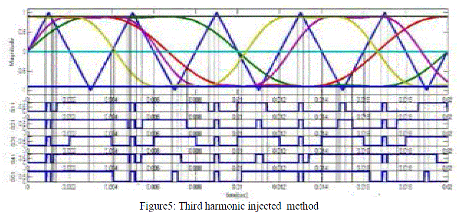 |
| Third harmonic injection method [8] is commonly used to increase the range of modulation index (M)so as to increase
system voltage gain range. There are seven modulation curves in this control method:five reference signals, and two
shoot-through dcsignals, Vpand Vn.A third harmonic component with 1/6th of the fundamental component is injected to
the voltage references. When the carrier triangle waves is greater than the upper shoot-through dc signal, Vp, or lower
than the lowershoot-through dc signal, Vn, the inverter is turned to a shoot-through zero state.In between, the inverter
switches in the same wayas in traditional carrier-based PWM control.The sketch map of maximum constant boost
control is shown in Figure(5).Thismethod achieves maximum boost whilekeeping the shoot-through duty ratio always
constant; thus it results in low line frequencycurrent ripple through the inductors. With this method, the inverter can
buck and boost the voltage from zero to any desiredvaluesmoothly within the limit of the device voltage.This method is
especially suitable for low-frequency applications, since it minimizes the Z-source network.
Table I shows the summary of all relations for different PWM control methods. |
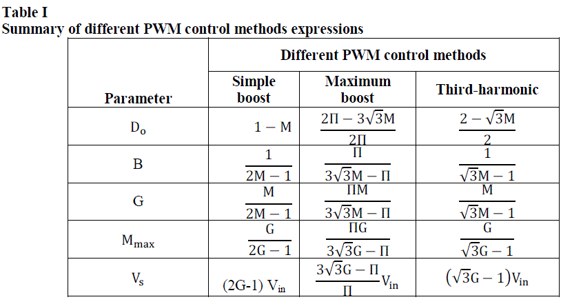 |
| The above table shows that the comparisons of differentPWM methods of various parameters. Among these methods
Maximum-boost method produces more voltage but it has some limitations discussed above and more significantly
third-Harmonic or constant-boost PWM method is used. |
HIGH PERFORMANCE Z-SOURCE FIVE-LEG INVERTER |
| The Z-source inverter operating with small inductance has some limitations as following: |
| 1. When the inductance of the z-network is small, the inductor current can become highripple or even
discontinuous. |
| 2. The Z-source network inductor has the limited value to guarantee the input current Iin > 0 . In some
applications, the inductance should be minimized in order to reduce cost, size, and weight. The design of Z-source
network inductor and systemcontrol become very complex, and the output voltagebecomes incontrollable withsmall
inductor evenoperate in full load. |
| 3. Light-load operation is the problem in Z-source inverter. The dc-link voltage isincreasing infinitelywhen the
system operated with light-load, which causes voltage-drops at the dc-link. The voltage will be uncontrollableand the
system is unstable. |
| To overcome these limitations, high-performance Z-source structure is employed [9, 10]. Whilemaintaining all the
benefits of conventional Z-source inverters,this structure can be used for a wide range of load changes(even no-load
mode), operates with smaller inductors in Z-sourcenetwork, eliminate the possibility of the dc-link voltagedrops, and
simplify the inductor design and system control. The structure of ahigh-performance Z-sourceinverter is shown in
figure 6. |
 |
| The high-performance Z-source inverter has two modes of operations and is explained below. In this method the peak
value of ac output phase voltage for each load can be written as: |
 |
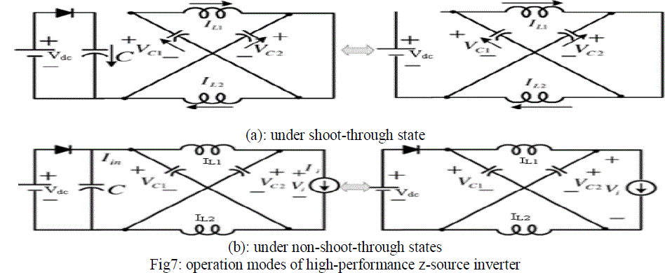 |
| The switch‘s’ is controlled in such a way that it is inOFF state when inverter is in shoot-through state andswitchis in
ON state when inverter is in non-shoot through state. In this structure, the gate signal for switch‘s’ can be generated
withboth modulation methods of simple-boost and maximum-boost.The pulses for switch‘s’ is generated by using
simple boost method shown in Fig.8. |
 |
 |
SIMULATION RESULTS |
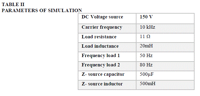
| To verify the validity of these methods as explained above various simulations areperformed. The simulation
parameters are given in Table II. Inorder to show that the Z-source Five-Leg inverter is able to control eachload
independently, the load frequencies are assumed to bedifferent. |
 |
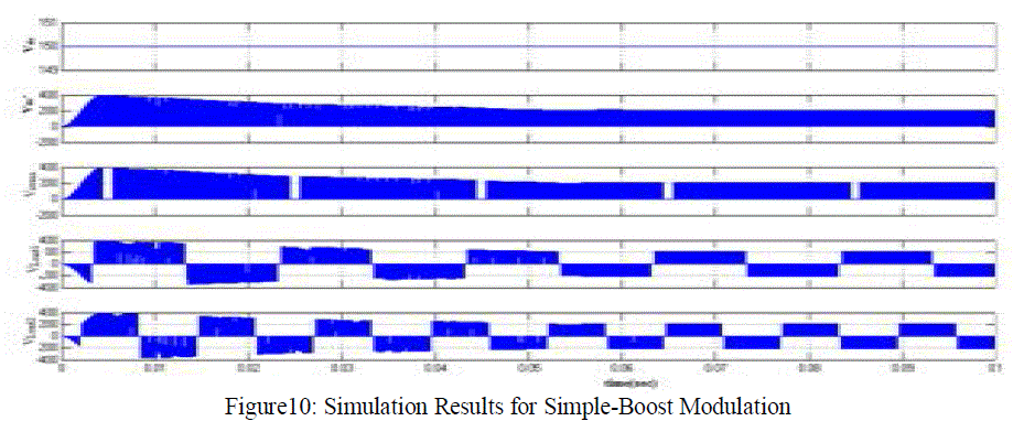
| The simulation results of five-leg z-source inverter with simple-boostmodulation method are shown in figure10. The
impedance or Z- network boost this DC voltage to 215V (peak) forModulation index of 0.85. It can be seen that the
voltage stress on theswitches is increased. For example, when switch S11 is OFF,the voltage across this switch
increases to about 215 volts.According to these results, the Z-source five leg-Inverter withthe simple boost modulation
method can independentlycontrol the frequency for each of two loads. But inthis method all the shoot-through states are
not fully utilized and boosted voltage is also relatively low. |
 |
| At the same condition, to increase the inverter DC linkvoltage, maximum boost method is employed. With the same
parameters used for the simple-boost method, DC link voltage is unstable. The reason is thatinstead of three reference
waves, two waves areproducing short circuit signals for each load and zeroreference does not have any effect on short
circuit signals.This causes the increase in the short circuit time.To compensate this and stabilize the system, a limit for
short-circuit time is considered. In this simulation, a maximum short-circuit time of 20% was assumedin each halfperiod.
Simulationresults are shown in Figure11. |
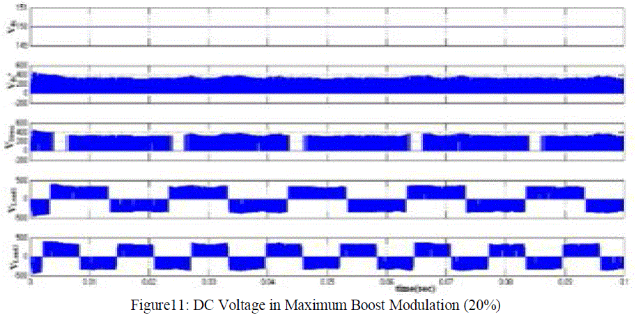 |
| In Figure11, with DC input Voltage equal 150V, DC voltage ofZ-source network is boosted to a value ofaround 340V
whichis more than twice that of the input voltage. Also, like in the previousmethod, the voltage stress on the switches is
increased. Forexample, when switch Sll is OFF, voltage Sll increases to about 340V. In thisfigure, turn-on time of the
switches isincreased which results in more conduction loss in theswitches. According to these results, the Z-source FLI
utilizingthe maximum boost modulation method can independentlycontrol the frequency for each of two loads. |
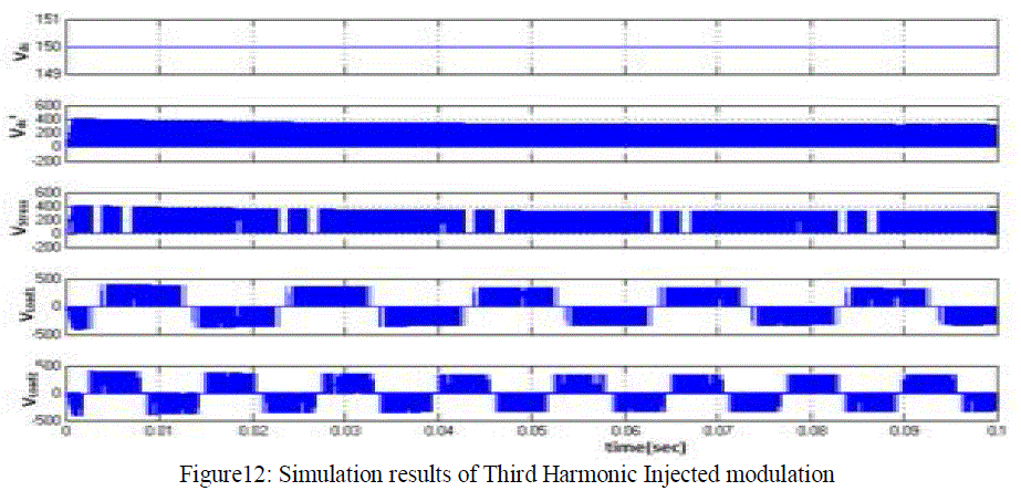
| In the above two methods the voltage across the switch is more this results in high cost because we require high rating
switches. So to decrease voltage stress and to increase the modulation index range another method is used i.e., Third
Harmonic injected PWM method. The simulation results are shown in figure12. With DC input voltage of 150V is
boosted to around 315V. |
 |
 |
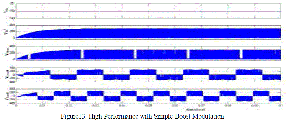
| At the same condition, to increase the stability, high-performance method is used. Simulations for high-performance Zsource
FLI are performed with simple boost and maximum-boost modulation methods. Simulation resultsfor simpleboost
are shown in Figure13.Again, with DC inputVoltage equal to 150V, DC voltage ofZ-source network is increased
to about 280V, but as it is clearin Fig. 13, the voltage ripple is decreased in this case.According to these results, the
high performance Z-source five-leg Inverter with the simple boost modulation method canindependently control the
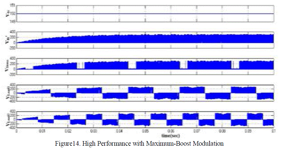
frequency for each of two loads.At the same condition, to increase the inverter DC linkvoltage, maximum boost
modulation method inhigh-performance Z-source five leg inverter is used. Simulationresults are shown in Figure14.In
this figure, with DC input Voltage equal to 150V, DCvoltage Z-source network is boosted to 300V and systembecomes
stable. |
 |
 |
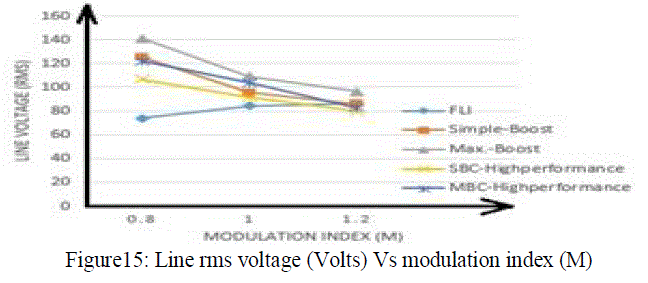
| The following figure15 shows that the comparison of rms line voltage versus modulation index (M) for different
methods of Five-Leg inverter. Among these methods Maximum-Boost PWM method produces the highest output
voltage because in this method all zero states are utilized fully. |
 |
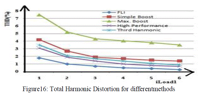
| Total Harmonic Distortion is an important parameter to determine the quality of a wave form. In thissection, the
valueofTHD is calculated for output load current. Figure16 shows thevalue of THD for different methods.As can be
seen in this figure, the FLI has the lowest THDwhile maximum-boost modulation in Z-source FLI results inthe highest
THD. |
 |
CONCLUSION |
| This paper presents control methods for controlling two independent loads simultaneously by using Five-leg Z-Source
inverter and High-Performance Z-Source Inverter. The Z-Source Five-Leg inverter to overcome the limitations of the
traditional five-leg inverter, however it has some limitations when operating at light-loads or with small Z-source
network inductor. To overcome these limitations High-Performance Z-source inverter is proposed. Moreover it also
has lower harmonics, less stress across theswitches,removesDC link voltage drops,simplifies the design of inductor and
stability can be improved. Finally, simulation results verified for the validity of various control methods. |
References |
- Ryuji Omata, Kazuo Oka, Atsushi Furuya, ShujiMatsumoto, Yusuke Nozawa, KoukiMastsuse, âÃâ¬ÃÅ An Improved Performance of Five-Leg Inverter in Two Induction Motor DrivesâÃâ¬ÃÂ, Dept. of Electrical and Electronics Engineering, Kawasaki, JAPAN, IEEE Power Electronics and Motion Control Conference, pp.4244-0448,(2006)
- Yusuke Ohama, Kazuo Oka, and KoukiMastsuse, âÃâ¬ÃÅ Characteristics of Independent Two Induction Motor Drives Fed by a Five-Leg InverterâÃâ¬ÃÂ, Department of Electrical and Electronics Engineering, Meiji University, Higashimita, Tama-ku, Kawasaki, JAPAN, IEEE Electrical Machines and Systems Conference, pp-4244-5177, (2009)
- Kazuo Oka, Yusuke Nozawa, KoukiMastsuse, âÃâ¬ÃÅ Improved Method Voltage Utility Factor for PWM Control Method of Five-Leg Inverter âÃâ¬ÃÅ, Meiji University Dept. of Electrical and Electronics Engineering, Meiji University, Higashimita, Tama-ku, Kawasaki, JAPAN, IEEE Electrical Machines and Systems Conference, pp-4244-5177, (2006)
- Tsutomu Kominami, Yasutaka Fujimoto, âÃâ¬ÃÅ Inverter With Reduced Switching-Device Count for Independent AC Motor Control âÃâ¬ÃÅ, Department of Electrical and Computer Engineering Graduate School of Engineering Yokohama National University, The 33rd Annual Conference of the IEEE Industrial Electronics Society (IECON), pp-4244-0783, (2007)
- Martin Jones, DrazenDujic, Emil Levi, âÃâ¬ÃÅ A Performance comparison of PWM Techniques for Five-Leg VSIs Supplying Two-Motor DrivesâÃâ¬ÃÂ, School of Engineering Liverpool, The 34rd Annual Conference of the IEEE Industrial Electronics Society (2008)
- F.Z. Peng, âÃâ¬ÃÅ Z-Source InverterâÃâ¬ÃÂ, IEEE Trans. Ind Appl., Vol. 39, No.2, pp. 504-510, (2003)
- F.Z. Peng, âÃâ¬ÃÅ Maximum Boost Control of the Z-Source InverterâÃâ¬ÃÂ, IEEE Trans. Power Elec., Vol. 20, No.4, pp.833-838, (2005)
- M. Shen, J. Wang, A. Joseph, F. Z. Peng, M. L. Tolbert and D. J. Adams, âÃâ¬ÃÅMaximum Constant Boost Control of the Z-Source InverterâÃâ¬ÃÂ, In Proc. Of IEEE Ind. Appl. Conf., Vol. 1, pp. 142-147, (2004)
- X. Ding, Z. Qian, S. Yang, B. Cui and F. Z. Peng, âÃâ¬ÃÅA High-Performance Z- Source Inverter Operating with Small Inductor at Wide-Range LoadâÃâ¬ÃÂ, In Proc. Of IEEE Power Elec., conf., pp. 615-620, (2007)
- X. Ding, Z. Qian, S. Yang, B.Cui and F. Peng, âÃâ¬ÃÅA New Adjustable- Speed Drives (ASD) System Based on High- Performance Z- Source Inverter, In Proc. Of IEEE Ind. Appl. Confr., pp. 2327-2332, (2007)
- P. C. Loh, D. M. Vilathgamuwa, Y. S. Lai, G. T. Chua, and Y. W. Li,âÃâ¬ÃÅPulse-width modulation of Z-source inverters,âÃâ¬Ã IEEE Trans. Power Electron.,vol. 20, no. 6, pp. 1346âÃâ¬Ãâ1355, Nov. 2005.
- M. Hanif, M. Basu, and K. Gaughan, âÃâ¬ÃÅUnderstanding the operation of a Z-source inverter for photovoltaic application with a design example,âÃâ¬ÃÂIETPower Electron., vol. 4, no. 3, pp. 278âÃâ¬Ãâ287, Mar. 2011.
|