A single-phase grid-connected converter is usually adopted in low-power renewable systems. This paper deals with a novel five-level converter topology that follows this development.. The proposed converter architecture is based on a full-bridge topology with two additional power switches and two diodes connected to the midpoint of the dc link. Since the two added levels are attained by the discharge of the two capacitors of the dc link, the midpoint voltage is balanced and obtained with a specific pulse width modulation (PWM) strategy. This solution is designed for renewable energy systems, where unity power factor operations are generally required. Never the less, a variation of the proposed topology which allows four-quadrant operations
Keywords |
| Distributed power Generation, DC–AC power conversion, grid-connected converters, Single-phase
systems, multilevel converters. |
INTRODUCTION |
| With regard to harmonic distortion content, power factors, and dc components, the output current of grid connected
power converters must comply with the requirements of electricity supply companies. Recently, converter topologies
employing a high-frequency transformer instead of a line frequency one have been investigated in order to reduce size
and weight. The trade-off between high efficiency and low cost is a hard task for these architectures because they
require several power stages. |
| On the other hand, in low-power applications, international standards permit the use of grid-connected power
converters without any galvanic isolation, thus allowing the so called transformer less architectures. |
| This paper concerns the use of multilevel topologies for single-phase converters, but in order to remain linked to a
practical implementation, the unipolar PWM applied to a full bridge topology is taken as reference. It is important to
note that, in this paper, the term unipolar PWM refers to a three-level output voltage, whose first switching harmonic
resides at twice the switching frequency. The unipolar PWM is always applied to a full-bridge structure. |
| Multilevel converter allow to reduces the harmonic content of the converter output voltage, allowing the use of smaller
and cheaper output filters. Moreover, these converters are usually characterized by a strong reduction of the switching
voltages across the power switches, permitting the reduction of switching power losses and electromagnetic
interference.The cascaded full-bridge allows multiple PWM strategies, i.e., carrier-based modulations or space-vector
approaches. In the field of carrier-based PWM, unipolar and hybrid modulations can be applied. |
LITERATURE SURVEY |
| Title : Transformer less single-phase multilevel-based photovoltaic inverter |
| Author : R. Gonzalez, E. Gubia, J. Lopez, and L. Marroyo |
| Publish : IEEE Trans. Ind.Electron., vol. 55, no. 7, pp. 2694–2702, Jul. 2008 |
| The elimination of the output transformer from grid connected photovoltaic (PV) systems not only decreases the cost,
size, and weight of the conversion stage but also increases the system overall efficiency. But, if the transformer is
detached, the galvanic isolation between the PV generator and the grid is lost. This may cause protection hazards in the
event of ground faults. Furthermore, the circulation of leakage currents (common-mode currents) through the stray
capacitance between the PV array and the ground would be enabled. Also, when no transformer is used, the inverter
could insert direct current (dc) to the grid, producing the saturation of the transformers along the distribution network.
Whereas safety requirements in transformer less systems can be met by means of exterior elements, leakage currents
and the injection of dc into the grid must be guaranteed topologically or by the inverter’s control system. |
| Title :Eliminating ground current in a transformer less photovoltaic application |
| Author :O. Lopez, F. D. Freijedo, A. G. Yepes, P. Fernandez-Comesaa, J. Malvar, R. Teodorescu, and J. Doval-
Gandoy |
| Publish :IEEE Trans. Energy Convers., vol. 25, no. 1, pp. 140–147, Mar. 2010 |
| For low-power grid-connected applications, a single phase converter can be used. In photovoltaic (PV) applications, it
is possible to get rid of the transformer in the inverter to reduce losses, costs, and size. Galvanic linking of the grid and
the dc sources in transformer less systems can introduce additional ground currents due to the ground parasitic
capacitance. These currents rise conducted and radiated electromagnetic emissions, harmonics inserted in the utility
grid, and losses. Spectrum and amplitude of the ground current depend on the converter topology, the switching plan,
and the resonant circuit formed by theac filter, ground capacitance,the grid andthe converter. In this paper, the ground
current in a 1.5-kW PV installation is noted under different conditions and used to build a simulation model. The
installation contains a string of a full-bridge inverter,LCL filter and an16 PV panel. This model allows the study of the
influence of the harmonics injected by the inverter on the ground current. |
| Title : Recent advances and industrial applications of multilevel converters |
| Author : S. Kouro, M. Malinowski, K. Gopakumar, J. Pou, L. Franquelo, B. Wu, J. Rodriguez, M. Pandrez,
and J. Leon |
| Publish : IEEE Trans. Ind. Electron., vol. 57, no. 8, pp. 2553–2580, Aug. 2010 |
| Multilevel converters have been under research and development for more than three decades and have found
successful industrial application. Nevertheless, this is still a technology under development, and many new assistances
and new commercial topologies have been reported in the last few years. The goal of this paper is to group and review
these recent assistances, in order to establish the current state of the art and trends of the technology, to offer readers
with a comprehensive and insightful review of where multilevel converter technology stands and is heading. This paper
first presents a brief summary of well-established multilevel converters strongly oriented to their current state in
industrial applications to then centre the discussion on the new converters that have made their way into the industry. |
CIRCUIT TOPOLOGY |
| Block Diagram of Proposed Topology |
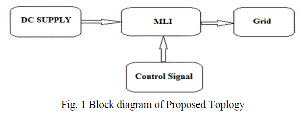 |
| Block diagram consist of multi-level inverter which is triggered by the control signals and the result is fed to the Grid. |
| Proposed Five-Level Single –Phase Solution |
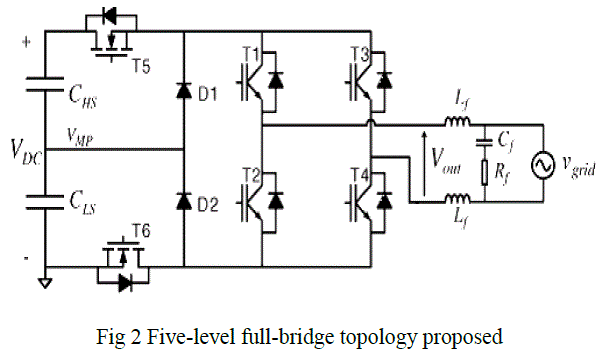 |
| The proposed converter is shown in Fig. 2. This converter architecture, known as the H6 Bridge, was originally
developed, in combination with a suitable PWM strategy, in order to keep constant the output common-mode voltage in
case of a transformer less inverter for photovoltaic applications. With the same purpose, another PWM strategy for the
H6 Bridge was developed. In this paper, this converter structure is used to obtain a five-level grid-connected converter
for single-phase applications. In steady-state conditions, due to the low voltage drop across the inductance Lf of the
output filter, the output voltage of the converter has a fundamental component very close to the grid voltage. The
frequencies of these two voltages are identical, whereas the amplitude and their phase displacement are only slightly
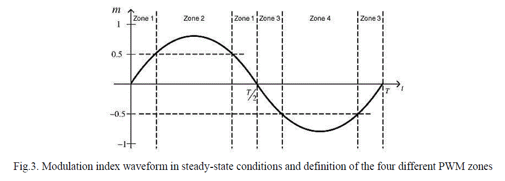
different. As a consequence, the shape of the modulation index m of the power converter is very similar to the grid
voltage waveform. |
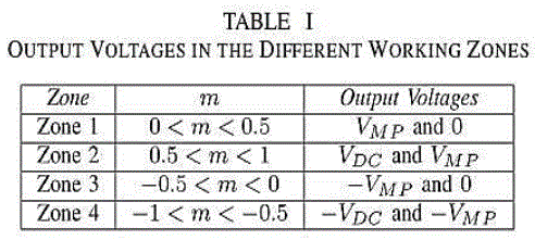
| The output voltage of the converter can be written as Vout = mVdc Depending on the modulation index value, the
power converter will be driven by dissimilar PWM strategies. As a matter of fact, it is possible to identify four
operating zones, and for each zone, the output voltage levels of the power converter will be different, as shown in Table
I. |
 |
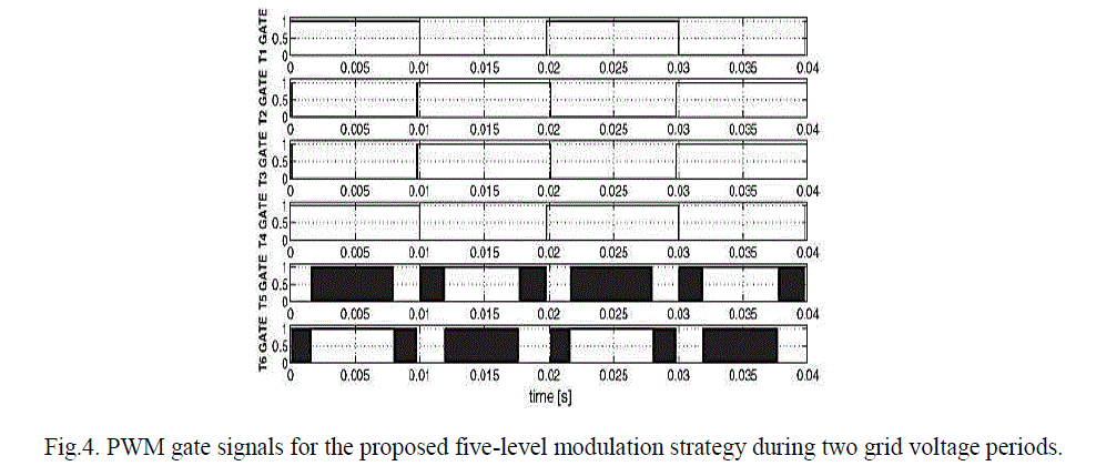
| With reference to the schematic, the behavior of the proposed solution is shown for a whole period of the grid voltage,
i.e., of the modulation index. During the positive semi period the transistors T1 and T4 are ON and T2 and T3 are OFF.
In Zone 1, T5 is OFF and T6 commutates at the switching frequency, whereas in Zone 2 T5 commutates at the
switching frequency and T6 is ON. During the negative semi period the full-bridge changes configuration, with T1 and
T4 OFF and T2 and T3 ON. With similarity to Zone 1 and 2, Zone 3 at T5 |
OPERATION MODES IN PROPOSED FIVE-LEVEL SOLUTION |
| In Zone 1 the switching of the transistor T6 changes the output value between +Vmp [that is provided by the low-side
capacitor] and 0 V. It must be noted that only a transistor is switching for every zone. |
 |
| Furthermore, the antiparallel diode of every power switch is not used allowing the use of MOSFETs for all the
transistors. The gate signals for the proposed five level modulation strategies. |
 |
 |
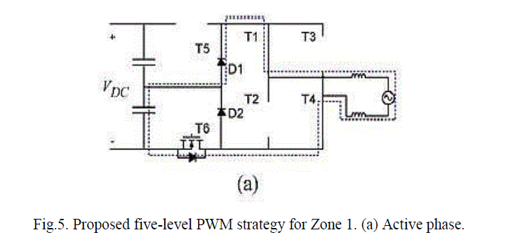 |
| This choice allows obtaining the minimum number of commutations but causes a voltage ripple in VMP at the same
frequency of the grid voltage. |
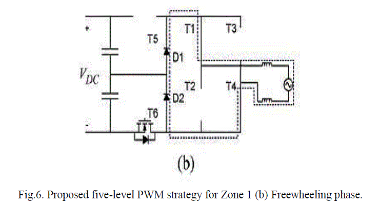 |
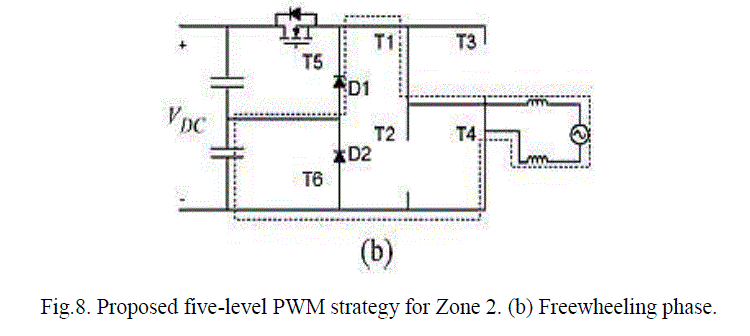
| During the freewheeling phase both diodes D1 and D2 are ON, imposing an almost null voltage at the full-bridge
output. |
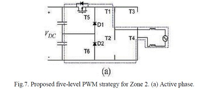 |
| In Zone 2 T6 is ON and the switching of T5 changes the output voltage from +VDC to+VMP. A similar analysis can be
repeated for the negative semi period, Zones 3 and 4. |
 |
| In fact, it would be possible to reduce the ripple of the midpoint voltage +VMP , but it would imply a greater number of
commutations of T5 and T6. This choice is dodged in order to follow the maximum efficiency. |
SIMULATION RESULTS |
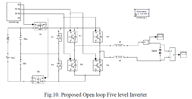 |
| A simulation design modulation technique as shown in Fig.10 is implemented in MATLAB SIMULINK with the help
of pulse generators where the Open loopis varied. Using the model grid voltages and currents THD levels are obtained. |
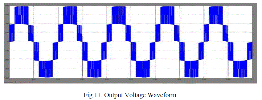 |
| The output voltage of the proposed five-level converter based on a full-bridge converter with two added power
switches and two diodes connected to the midpoint of the dc link obtained in the Simulink model is ±400 VOLTS peakpeak
and the output waveforms are showed in Fig. 11 |
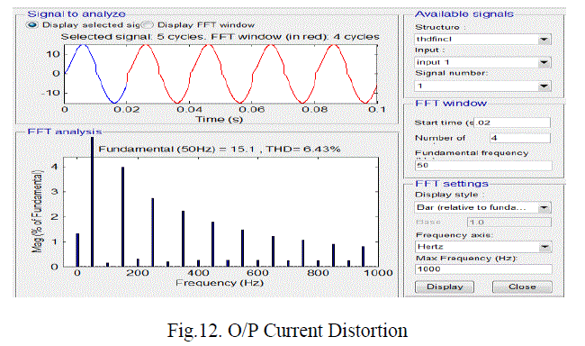 |
| The THD analysis is also compared for the simulation which is shown in Fig. 12.The total harmonic distortion in grid
currents is 6.43% for the selected signals of five obtained using the FFT analysis |
CONCLUSION |
| This paper has dealt with a novel five-level solution for single-phase grid-connected converters. The converter topology
uses the midpoint voltage of the dc link to provide two more output voltage levels, decreasing switching power losses
and EMI. Moreover, an effective balancing control (i.e., MVC) was implemented. It is important to note that the five
level output voltage is guaranteed only with a unity power factor operations; otherwise, the converter can output only
three voltage levels, thus increasing THD and switching loss. |
References |
- D. Infield, P. Onions, A. Simmons, and G. Smith, ―Power quality from multiple grid-connected single-phase inverters, IEEE Trans. Power Del., vol. 19, no. 4, pp. 1983–1989, Oct. 2004.
- R. Gonzalez, E. Gubia, J. Lopez, and L. Marroyo, ―Transformer less single-phase multilevel-based photovoltaic inverter, IEEE Trans. Ind.Electron., vol. 55, no. 7, pp. 2694–2702, Jul. 2008.
- S. Kouro, M. Malinowski, K. Gopal Kumar, J. Pou, L. Franquelo, B. Wu, J. Rodriguez, M. Panders, and J. Leon, ―Recent advances and industrial applications of multilevel converters, IEEE Trans. Ind. Electron., vol. 57,no. 8, pp. 2553–2580, Aug. 2010.
- J.-S. Lai and F. Z. Peng, ―Multilevel converters—A new breed of power converters, IEEE Trans. Ind. Appl., vol. 32, no. 3, pp. 509–517, May 1996.
- A. Shukla, A. Ghosh, and A. Joshi, ―Control schemes for dc capacitor voltages equalization in diode-clamped multilevel inverter-based D statcom, IEEE Trans. Power Del., vol. 23, no. 2, pp. 1139–1149, Apr. 2008.
- A.Bendre, G. Venkataramanan, D. Rosene, and V. Srinivasan, ―Modelling and design of a neutral-point voltage regulator for a three-level diode clamped inverter using multiple-carrier modulation, IEEE Trans. Ind.Electron., vol. 53, no. 3, pp. 718–726, Jun. 2006.
- L. Zhang and S. Watkins, ―Capacitor voltage balancing in multilevel flying capacitor inverters by rule-based switching pattern selection,Elect. Power Appl., vol. 1, no. 3, pp. 339–347, May 2007.
- E. Villanueva, P. Correa, J. Rodriguez, and M. Pacas, ―Control of a single-phase cascaded h-bridge multilevel inverter for grid-connected photovoltaic systems, IEEE Trans. Ind. Electron., vol. 56, no. 11, pp. 4399–4406, Nov. 2009.
- C. Cecati, F. Ciancetta, and P. Siano, ―A multilevel inverter for photovoltaic systems with fuzzy logic control, IEEE Trans. Ind. Electron., vol. 57, no. 12, pp. 4115–4125, Dec. 2010.
- M. Malinowski, K. Gopalkumar, J. Rodriguez, and M. Pandrez, ―A survey on cascaded multilevel inverters, IEEE Trans. Ind. Electron., vol. 57, no. 7, pp. 2197–2206, Jul. 2010.
|