International Journal of Advanced Research in Electrical, Electronics and Instrumentation Engineering
ISSN ONLINE(2278-8875) PRINT (2320-3765)
ISSN ONLINE(2278-8875) PRINT (2320-3765)
T.Nelson1 and Dr.D.Mary2
|
| Related article at Pubmed, Scholar Google |
Visit for more related articles at International Journal of Advanced Research in Electrical, Electronics and Instrumentation Engineering
During voltage sags, continuous power delivery from distributed generation systems to the grid is desirable for the purpose of grid support. Ancillary services for distributed generation (DG) systems become a challenging issue to integrate renewable-energy sources into the grid. Voltage control is one of these ancillary services which can ride through and support the voltage under grid faults. In order to facilitate the control of distributed generation systems adapted to the expected change of grid requirements, flexible voltage support control scheme is proposed for inverter based distributed generation, aiming at regulating voltage limits and reactive power injection to remain connected and supports the grid under fault. In three-phase balanced voltage sags, the inverter should inject reactive power in order to raise the voltage in all phases. In one- or two-phase faults, the main concern of the DG inverter is to equalize voltages by reducing the negative symmetric sequence and clear the phase jump. Thus, over and under voltage can be avoided, and the proposed control scheme prevents disconnection while achieving the desired voltage support service which can be analyzed and simulated by using Matlab/Simulink environment. The main contribution of this work is the introduction of a control algorithm for reference current generation that provides flexible voltage support under grid faults.
Keywords |
| Distributed generation (DG), grid-connected inverter, reactive power control, voltage sag, grid fault. |
INTRODUCTION |
| Total installed power from renewable-energy sources is constantly growing in the new electric deregulated scenario. Among them, photovoltaic and wind turbine are gaining increasing attention in the last few years [1]. When connected to the grid, renewable-energy sources behave as distributed generation (DG) systems [3]. Conventionally, a distributed generation system would be required to disconnect from the grid when voltage dips occur and to reconnect to the grid when faults are cleared. Voltage dips, usually caused by remote grid faults in the power system, are shortduration decreases in rms voltage [2]. Most voltage dips are due to unbalanced faults, while balanced voltage dips are relatively rare in practice [4], [7]. However, this requirement is changing. For the voltage support, a power quality compensator to keep the microgrid voltage immune to unbalanced grid faults [1], [2]. It is very effective but needs additional series compensation devices. In order to overcome the limitation, a powerful voltage support control for the grid-connected inverter under unbalanced grid faults [3], which enables both the positive sequence voltage recovery and negative sequence voltage reduction. Indeed, it is valid on the assumption that the network impedance is mainly inductive. With the increasing application of renewable energy sources, more and more DG systems actively deliver electricity into the grid. Consequently, in order to maintain active power delivery and reactive power support to the grid, grid codes now require wind energy systems to ride through voltage dips without interruption [5], [6]. Concerning the control of DG inverters under voltage dips, especially unbalanced situations, two aspects should be noticed. Firstly, fast system dynamics and good reference tracking are necessary. The basic element for interconnecting DG to the transmission system is the three-phase inverter [9]. In normal grid conditions, three-phase DG inverters inject all the generated active power into the grid. One of the major drawbacks for proper operation of the whole system occurs when voltage sag (dip) is transmitted through the network. In grid fault conditions, the controller must react to the perturbation and mitigate the adverse effects on the inverter side. Depending on the depth and duration of the voltage sag, the grid codes force disconnection of the system [7], [8]. In this paper, a flexible control algorithm is proposed to face the problem of different types of voltage sags. Whenever balanced three-phase voltage sags occur, the voltage support strategy should raise the voltage in all phases as much as possible. However, if only one or two phases are in fault, a voltage equalizing strategy will be of interest. Voltage equalization is accomplished when the difference between rms voltages is reduced. Then, it is possible to avoid under voltage in the phases under fault or overvoltage in the phases that do not suffer the voltage sag. Moreover, the negative-sequence voltage is reduced and the phase jump is cleared, which are important arguments to properly operate DG inverters [10]. To avoid disconnection, phase voltages must remain within upper and lower limits. Novel control schemes are needed for a greater penetration of DG sources. Better control algorithms improve power quality and efficiency and increase grid reliability as well [11], [12]. Therefore, control schemes with higher performance are the basis for proper operation of DG systems, particularly under grid faults. |
THREE-PHASE DG INVERTER |
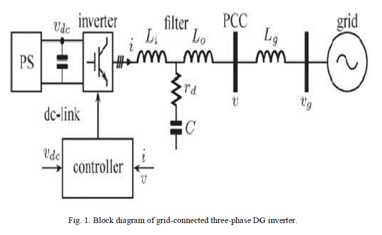
| The complete system is composed of the power source (PS), the inverter, and the grid is shown in Fig. 1. Interconnection between the PS and the inverter is operated by a dc-link capacitor. The control of the dc-link voltage Vdc balances the power flow in the system. The inverter consists of a three-leg voltage-source pulse width-modulation inverter with an LCL filter to reduce high-frequency harmonics. To avoid filter resonance, a passive damping resistor is included in series with the capacitor. Finally, the DG inverter is connected to the grid at the point of common coupling (PCC). Grid impedance is mainly inductive [1], so the inductance Lg is used to model the connection between the threephase DG inverter and the grid. Grid voltage Vg can be affected by the fault produced somewhere in the transmission system. During grid faults, the network node voltage profile will deteriorate. In order to provide the voltage support function, the grid-connected inverter should inject he power into the network for improving the bus voltage profile. |
 |
| A. Voltage Sag |
| Electronic devices function properly as long as the voltage of the electricity feeding the device stays within a consistent range. There are several types of voltage fluctuations that can cause problems, including surges and spikes, sags, harmonic distortions, and momentary disruptions. Voltage sag is a fundamental frequency decrease in the supply voltage for a short duration. Voltage sag is not a complete interruption of power; it is a temporary drop below 90 percent of the nominal voltage level. Most voltage sags do not go below 50 percent of the nominal voltage, and they normally last from 3 to 10 cycles or 50 to 170 milliseconds. Voltage sags are probably the most significant power quality (PQ) problem facing industrial customers today, and they can be a significant problem for large commercial customers as well. There are two sources of voltage sags: external and internal. Utilities continuously strive to provide the most reliable and consistent electric power possible. In the course of normal utility operations, however, many things can cause voltage sags. Storms are the most common cause of external sags and momentary interruptions in most areas. Internal causes of voltage sags can include starting major loads and grounding or wiring problems. Whether or not voltage sag causes a problem will depend on the magnitude and duration of the sag and on the sensitivity of your equipment. Many types of electronic equipment are sensitive to voltage sags, including variable speed drive controls, motor starter contactors, robotics, programmable logic controllers, controller power supplies, and control relays. There are several factors for the causes of voltage sags: |
| a. Since the electric motors draw more current when they are starting then it can run at their rated speed, starting an electric motor can be a reason of voltage sag. |
| b. When a line-to-ground fault occurs, there will be voltage sag until the protective switch gear operates. |
| c. Some accidents in power lines such as lightning or falling of an object cause of line-to-ground fault and voltage sag as a result. |
| d. Sudden load changes or excessive loads can cause voltage sag. |
| e. Depending on the transformer connections, transformers energizing could be another reason for happening voltage sags. |
| Voltage sag is an abnormal condition in the grid voltages, characterized by a short-time reduction in one or various phases. The causes of voltage sags are mainly phase-to-ground short circuit, phase-to-phase (to ground) short circuit, and the start-up of large motors. Voltage sags can be characterized by the module, frequency, and initial angle of each phase or by the positive, negative, and zero symmetric sequences: |
 |
| B. Control Diagram for Grid Connected Inverter |
| The behavior of the current-mode three-phase inverter is determined by the injected current at the PCC. By injecting reactive power into the grid, the rms voltage at the PCC can be increased to support the grid voltage under fault. Then, a proper reference current generator is required when the grid is under fault in order to counteract the voltage sag effects on the system. |
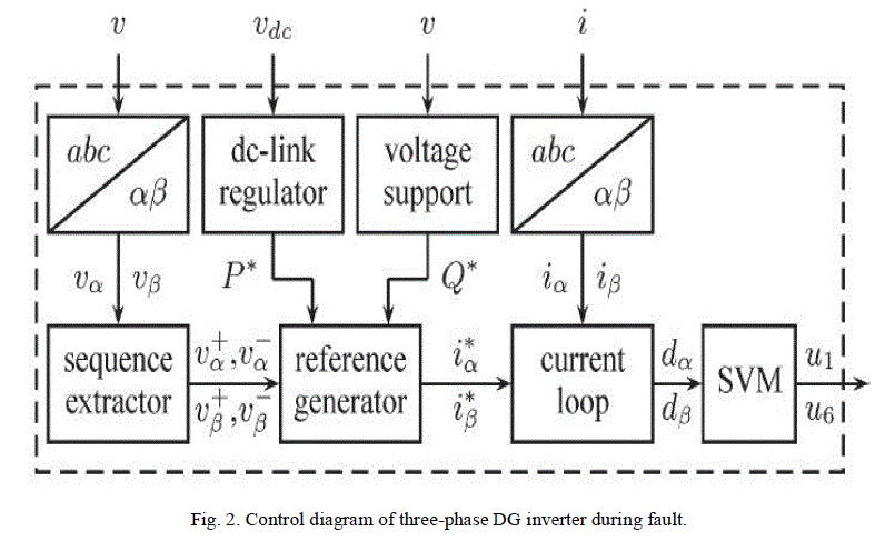 |
| The inputs of the controller are the measured phase voltages v at the PCC, the currents i flowing through Li inductor, and the dc-link voltage. Voltage v and current i are transformed into SRF values. Voltages and are then decomposed into symmetric components using a sequence extractor. The symmetric sequence extractor is a key aspect to characterize the grid voltage. The dc-link voltage regulator is in charge of the active power reference P* that keeps power balance. The voltage support block needs to detect the voltage sag. This can be done by computing the voltage rms in each phase. When one or several rms values drop below a predefined threshold, the voltage support control is activated. The voltage support block decides which strategy should be implemented according to grid codes and system limitations. This part provides the reactive power reference Q*. All this information passes through the reference generator to build reference currents and . The reference current generator is the kernel of the control algorithm because it can flexibly support the grid voltage. The next stage corresponds to the current loop, where the references are compared with the measured currents. At the end of the current control loop, duty cycles and are processed by the space vector pulse width modulator to commute the switches . The main objective of this work is to present a method to ride through voltage sags and support the grid voltage. In three phase balanced voltage sags, the control strategy should be to raise the voltage in all phases. In one or two-phase voltage sags, the controller is in charge of a grid current that equalizes voltages, i.e. within acceptable limits. |
| C. Reactive Power Control |
| Reactive power is the form of magnetic energy flowing per unit time in an electric circuit. Its unit is VAR (Volt Ampere Reactive). This power can never be used in an AC circuit. However, in a DC circuit it can be converted into heat as when a charged capacitor or inductor is connected across a resistor, the energy stored in the element get converted to heat. Our power system operates on AC system and most of the loads used in our daily life are inductive or capacitive, therefore reactive power is a very important concept from electrical perspective. The electrical power factor of any equipment determines the amount of reactive power it requires [7]. It is the ratio of real or true power to the total apparent power required by an electrical appliance. Voltage changes continuously according to the varying electrical demand, transmission lines utilization, system control by the control centers, and emergency situations occurred in the system. Since customers require voltage quality, at delivery points, to meet the agreed criteria, it is the control centers’ responsibility to control the voltage so that it can satisfy the agreement. Controlling the voltage is regional problems. In other words, the voltage controlling problems are needed to be solved separately by each control area. |
| D. Grid Code Requirements |
| The grid requirements for DGs are updated and revised based on the development and penetration level of DGs and issued in the form of national grid code, such as E.ON grid code and CEI grid code published by Comitato Elettrotecnico Italiano [13]. In these grid codes, the basic demands are imposed like the power quality (the THD level of the injected current) and the anti-islanding requirement. Considering the penetration level of DGs connected to the grid, combined requirements are expected to be added into the grid codes in the future. Transmission system operators (TSO) requirements in grid codes [1], [13] state that power generators should remain connected even in faulted grid conditions in order to feed the grid and support the grid voltage. Different TSOs provide different voltage profiles as limits for disconnection, depending on sag depth and duration. During a short interval (typically, less than 0.150 s), the inverter must remain connected even in very deep sag conditions [0.2 per unit (p.u.)]. In moderate voltage sags (below 0.8 p.u.), the inverter must remain connected for a longer time (2 s). Another issue in voltage support requirements is the reactive/active power ratio. In deep voltage sags, only the reactive power must be injected to the grid. However, in less deep voltage sags, both active and reactive powers must be transferred to keep feeding the grid. These grid requirements are set to ensure the safety of utility maintenance personnel and also other devices connected o the public grid and to avoid the grid collapse due to voltage faults. It is expected that these grid requirements will be recommended to be used to regulate single-phase PV systems [2], since the impact of large-scale single-phase PV systems on the low-level public grid cannot be ignored. |
PROPOSED VOLTAGE SUPPORT CONTROL |
| Under balanced grid conditions, the inverter extracts the maximum active power from the source and injects it into the grid. The reference currents for active power can be expressed as |
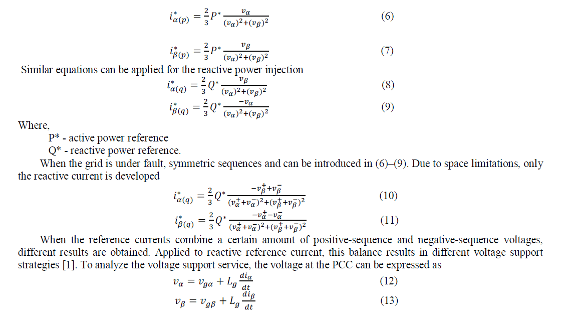 |
| By projecting this value from the grid voltage, the instantaneous voltage at the PCC i.e. the voltage support strategy is obtained. For a flexible voltage support, the balance of positive and negative-sequence components can be obtained with the following reactive current references: |
 |
SIMULATION RESULTS |
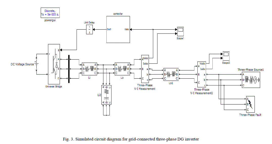
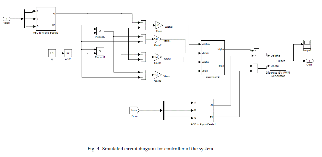
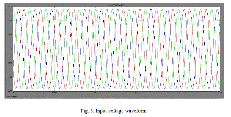
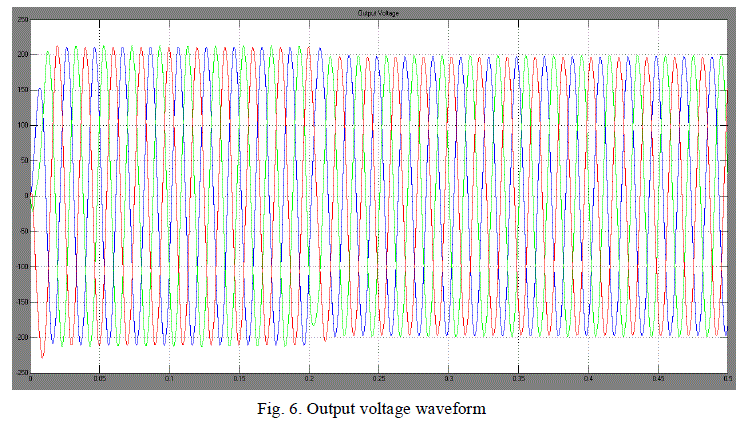
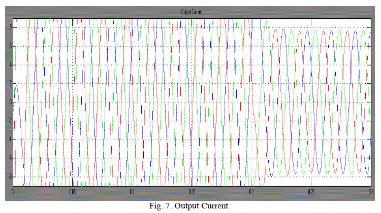
| Simulation has become a very powerful tool on the industry application as well as in academics, nowadays. It is now essential for an electrical engineer to understand the concept of simulation and learn its use in various applications. Simulation is one of the best ways to study the system or circuit behavior without damaging it. In most of the research and development (R&D) work, the simulation plays a very important role. The performance of the proposed concept of flexible voltage support control during simultaneous voltage sag compensation has been evaluated by using Matlab/Simulink environment. MATLAB is an interactive system whose basic data element is an array that does not require dimensioning. SimPowerSystems extends Simulink with tools for modeling and simulating basic electrical circuits and detailed electrical power systems. The proposed method can achieve more effective voltage support for the positive sequence voltage recovery and negative sequence voltage reduction in a grid. Fig. 3 and Fig. 4 shows that the simulation circuit diagram of the proposed voltage control scheme for the distribution generation of three-phase inverters. Here, the controller is a main component which can be used to analyze and reduce voltage sag during grid connection. The simulated output voltage and current waveforms in Fig. 5 and Fig. 6 shows that voltage sag is reduced by the controller during grid connection. It can be observed that the unbalance degree of the bus voltage is significantly decreased at the expense of the larger power oscillations, which would result in the dc-link voltage oscillations. Therefore, the control coefficient should be carefully tuned for the practical applications. On the other hand, the proposed control strategy is effective for both positive sequence voltage recovery and negative sequence voltage reduction, which will enhance the voltage support capability of the grid-connected inverter in the low voltage/voltage dip in a grid. |
 |
 |
| A. Simulation Results |
 |
 |
 |
CONCLUSION |
| This paper has proposed the method for flexible voltage support control of distributed generation inverters operating under grid fault. The obtained results indicate that the conventional control strategy is not effective in the low voltage grid, where the network impedance is mainly resistive. The voltage support strategy can be modified by means of a control parameter according to the type of voltage sag. When the sag is very deep, k+ should be near to zero; when the sag is less deep, a balance between these two extreme policies should be obtained. On the other hand, the proposed method can flexibly support the grid voltage with the positive sequence voltage recovery and negative sequence voltage reduction and also it clears the phase jump which is a powerful tool for voltage support under grid fault. |
References |
|