ISSN ONLINE(2278-8875) PRINT (2320-3765)
ISSN ONLINE(2278-8875) PRINT (2320-3765)
N.Balaji1 and R.Dharmaprakash2
|
| Related article at Pubmed, Scholar Google |
Visit for more related articles at International Journal of Advanced Research in Electrical, Electronics and Instrumentation Engineering
This paper provides a technical review of position and speed sensor less methods for controlling brushless direct current (BLDC) motor drives, including the background analysis using sensors, limitations and advances. The performance and reliability of BLDC motor drivers have been improved because the conventional control and sensing techniques have been improved through sensor less technology. This four quadrant operation of BLDC motor with load variations is simulated using MATLAB/SIMULINK software. The advances in Sensor less methods are reviewed and recent developments in this area are introduced with their inherent advantages and drawbacks, including the analysis of practical implementation issues and applications. The study includes a deep overview of state-of-the-art back-EMF sensing methods, which includes Terminal Voltage Sensing, Third Harmonic Voltage Integration, Terminal Current Sensing, Back-EMF Integration and PWM strategies. INDEX TERMS: BLDC motor, digital control, dsPIC, four quadrants, regenerative braking
INDEX TERMS |
| BLDC motor, digital control, dsPIC, four quadrants, regenerative braking |
INTRODUCTION |
| Brushless DC motors have gained increasing popularity in the recent years. BLDC motors have permanent magnets that rotate (rotor) and a fixed armature (stator). An electronic controller is used for motor commutation instead of the brushed commutation Used in the brushed DC motors. BLDC motors offer many advantages over the brushed DC motors, which include increased speed vs torque efficiency ,longer life noiseless operation, and increased efficiency in converting electrical power to mechanical power (especially because there are no electrical and frictional losses due to brushed commutation). The motor commutation in BLDC motors is implemented by an electronic controller and, to determine the rotor position and to know when to commutate, either Hall sensors (sensored commutation) or the back EMF generated in the stator windings of the motor (sensor less commutation) are used. Sensor less controllers have challenges during motor start-up, as no back EMF is present when the motor is stationary; this is worked around by starting the motor from an arbitrary position; however, this can cause the motor to briefly jerk or even rotate backward during start-up. Hall sensor based controllers are simpler to implement compared to the sensor less control and are used in applications that require good starting torque and that require the motors to run at lower speeds. BLDC motors are used in Automotive, Aerospace, Consumer, Medical, Industrial Automation equipments and instrumentation. |
| FOUR QUADRANT OPERATION OF BLDC MOTOR |
| A. BLDC Motor |
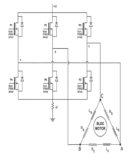
| Brushless DC Motors are driven by DC voltage but current commutation is controlled by solid state switches. The commutation instants are determined by the rotor position. The rotor shaft position is sensed by a Hall Effect sensor, which provides signals to the respective switches and. whenever the rotor magnetic poles pass near the Hall sensors, they give a high or low signal, indicating either N or S pole is passing near the sensors. The numbers shown around the peripheral of the motor diagram in represent the sensor position code. The north pole of the rotor points to the code that is output at that rotor position. The numbers are the sensor logic levels where the Most Significant bit is sensor and the Least Significant bit is sensor. Based on the combination of these three Hall sensor signals, the exact sequence of commutation can be determined. These signals are decoded by combinational logic to provide the firing signals for 120 conduction on each of the three phases. The rotor position decoder has six outputs which control the upper and lower phase leg MOSFETs. |
 |
| B. FOUR QUADRANT OPERATION |
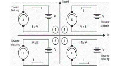
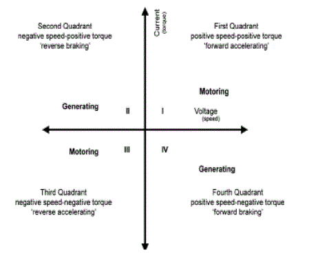
| There are four possible modes or quadrants of operation using a Brushless DC Motor which is depicted in When BLDC motor is operating in the first and third quadrant, the supplied voltage is greater than the back emf which is forward motoring and reverse motoring modes respectively, but the direction of current flow differs. When the motor operates in the second and fourth quadrant the value of the back emf generated by the motor should be greater than the supplied voltage which are the forward braking and reverse braking modes of operation respectively, here again the direction of current flow is reversed. The BLDC motor is initially made to rotate in clockwise direction, but when the speed reversal command is obtained, the control goes into the clockwise regeneration mode, which brings the rotor to the standstill position. Instead of waiting for the absolute standstill position, continuous energization of the main phase is attempted. This rapidly slows down the rotor to a standstill position. Therefore, there is the necessity for determining the instant when the rotor of the machine is ideally positioned for reversal. |
 |
 |
PI CONTROLLER |
| A proportional integral-derivative is the control loop feedback mechanism used. PI controller attempts to correct the error between a measured process variable and desired set point by calculating and then outputting corrective action that can adjust the process accordingly. The PI controller calculation involves two separate modes the proportional mode, integral mode. The proportional mode determine the reaction to the current error, integral mode determines the reaction based recent error. The weighted sum of the two modes output as corrective action to the control element. The speed of the motor is compared with its reference value and the speed error is processed in proportional- integral (PI) controller. The output of this controller is considered as the reference torque. A limit is put on the speed controller output depending on permissible maximum winding currents. |
| Digital Control |
| The BLDC motor is driven by rectangular voltage strokes coupled with the given rotor position; see The generated stator flux, together with the rotor flux, which is generated by a rotor magnet, defines the torque and thus the speed of the motor. To get the maximum generated torque, the voltage strokes must be applied to the 3-phase winding system, so that the angle between the stator flux and the rotor flux is kept close to 90°. To meet this criteria, the motor requires electronic control for proper operation. |
| PWM Module: |
| The PWM module simplifies the task of generating multiple synchronized Pulse Width Modulated (PWM) outputs. It has six PWM I/O pins with three duty cycle generators. The three PWM duty cycle registers are double buffered to allow glitch less updates of the PWM outputs. For each duty cycle, there is a duty cycle register that will be accessible by the user while the second duty cycle registers holds the actual compared value used in the present PWM period. |
SIMULINK MODEL |
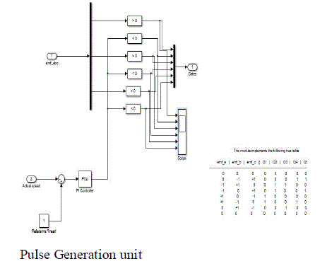
| The Simulink model of the BLDC motor. The closed loop controller for a three phase brushless DC motor is modelled using MATLAB/Simulink and Permanent Magnet Synchronous motor with trapezoidal back EMF is modelled as a Brushless DC Motor. The model of the controller shown in Fig. 8, receives the Hall signals as its input, converts it in to appropriate voltage signals. The gate signals are generated by comparing the actual speed with the reference speed. Thus a closed loop speed control is achieved with the help of PI control, present in the controller block. |
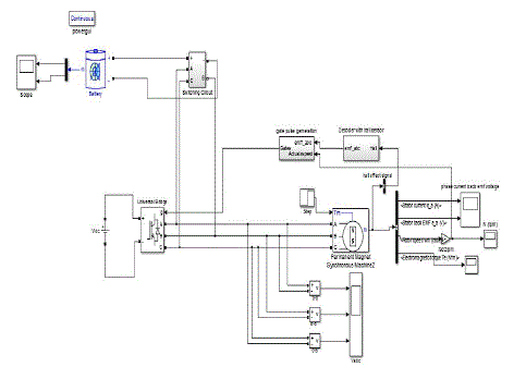 |
| Simulink Model of Four Quadrant Drive. |
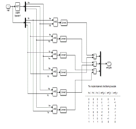 |
| EMF Generation unit |
 |
SIMULATION RESULTS |
 |
 |
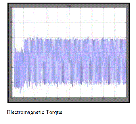 |
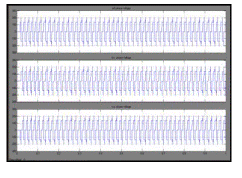 |
| Three phase output voltage |
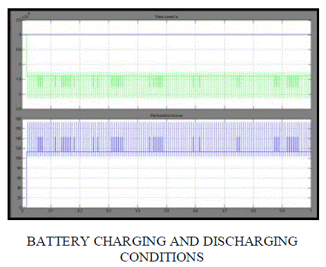 |
COMPLETE DRIVE SYSTEM |
| Four quadrant Zero current transition converter was implemented for DC motor and single controllable switch for four quadrant operation was implemented. The common regenerative braking methods include adding an extra converter, or adding an extra ultracapacitor, or switching sequence change of power switches. But the method of adding a converter not only increases cost but also reduces conversion efficiency. The method of adding an ultra-capacitor doesn’t require extra DC-DC converter, but it needs a sensor to detect the ultra-capacitor voltage. This makes the circuit very complex and hard to implement. Moreover ultracapacitor is very expensive. The method proposed in this paper is simple and reliable. It conserves energy in a rechargeable battery during the regenerative braking mode. Relay circuits are employed to run the motor during the accelerating mode and charge the battery during the regenerative mode. The position signals obtained from the Hall sensors of the motor are read by the I/O lines of the dsPIC controller. The Hall sensor inputs give the position of the rotor which is fed to the controller. The controller compares it with the reference speed and generates an error signal. The required direction of rotation either clockwise or counter clockwise can also be fed to the digital controller. The PWM module of the controller generates appropriate PWM signals, which are applied to the three phase inverter. Whenever there is a reversal of direction of rotation it implies there is a change in the quadrant. When the motor is operating in the motoring mode, in the clockwise direction, the relay contacts are normally open. But when braking is applied or when a speed reversal command is received, the relay contacts are closed. The kinetic energy which will be wasted as heat energy is now converted into electric energy which is rectified and stored in a chargeable battery. The braking energy can be given back to the power source. But it increases the complexity of the circuit, the DC power generated has to be inverted to be given back to the mains. |
CONCLUSION |
| The performance and reliability of BLDC motor drivers have been improved because the conventional control and sensing techniques have been improved through sensor less technology. This four quadrant operation of BLDC motor with load variations is simulated using MATLAB/SIMULINK software. The advances in Sensor less methods are reviewed and recent developments in this area are introduced with their inherent advantages and drawbacks, including the analysis of practical implementation issues and applications. The study includes a deep overview of state-of-the-art back-EMF sensing methods, which includes Terminal Voltage Sensing, Third Harmonic Voltage Integration, Terminal Current Sensing, Back- EMF Integration and PWM strategies. |
References |
|