International Journal of Advanced Research in Electrical, Electronics and Instrumentation Engineering
ISSN ONLINE(2278-8875) PRINT (2320-3765)
ISSN ONLINE(2278-8875) PRINT (2320-3765)
Geethu James1, Prof. K Radhakrishnan2 and Mrs.Jaya B3
|
| Related article at Pubmed, Scholar Google |
Visit for more related articles at International Journal of Advanced Research in Electrical, Electronics and Instrumentation Engineering
This paper describes the analysis and design of a low cost three phase inverter brushless dc motor (BLDC) drive. For effective utilization of the developed system, a novel direct current controlled pwm scheme (DPC) is designed and implemented.. The operational principle of the four-switch BLDC motor drive and the developed control scheme are theoretically analyzed and the performance is demonstrated by simulation.
Keywords |
| Brushless DC (BLDC) motor drive, four-switch inverter, Direct current control, Position sensorless control. |
INTRODUCTION |
| Permanent-magnet Brushless DC(PMBLDC) motors with trapezoidal back emf finds a variety of applications in aerospace, automotives, industries, military, computers, household products etc. due to higher efficiency, higher torque, higher power factor, increased power density, ease of construction ,ease of control and ease of maintenance. The torque developed by a BLDC motor is constant. A conventional Brushless DC motor is excited by a six switch three phase inverter (SSTPI) where commutation is achieved through an inverter and a position sensor placed 120° apart on the stator [4], [5]. Researchers are always conscious about their cost and are always exploring methods to bring in cost minimization. In this paper cost effectiveness is achieved by reducing the number of power switches, switching driver circuits, dc power supplies, total price and losses. |
 |
| Theoretical analysis and simulations on MATLAB/SIMULINK were conducted to demonstrate the feasibility of the proposed method. |
ANALYSIS OF A FSTPI-BLDC MOTOR DRIVE. |
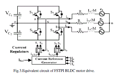
| The configuration of a four-switch three phase inverter (FSTPI) BLDC motor [4] is shown in fig 2. The equivalent circuit of the four switch inverter Brushless DC motor drive is shown in figure 3. |
 |
 |
| The equation of a typical BLDC motor is represented as follows: |
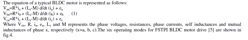 |
| Where Vxn, R, ia, ea, Ls and M represents the phase voltages, resistances, phase currents, self inductances and mutual inductances of phase x, respectively (x=a, b, c).The six operating modes for FSTPI BLDC motor drive [5] are shown in fig.4. |
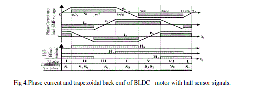 |
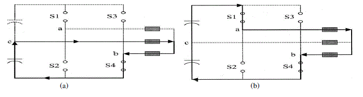
| A. Four-switch converter for BLDC motor drives. |
| In the four-switch configuration, the four switching status as shown in figure 5 are (0, 0), (0, 1), (1, 0), and (1, 1) where “0” means the lower switch is turned on and “1” means the upper switch is turned on [3]. In the case of six-switch converter, the switching status (0,0) and (1,1) cannot supply the DC –link voltage to the load. So the current cannot flow through the load at these instants and hence they are regarded as zero vectors. |
 |
| However, one phase of the motor is always connected to the midpoint of the dc-link capacitors in the four-switch converter, and hence current flows even at the zero-vector [1]. Moreover, the phase which is connected to the midpoint of dc-link capacitors is uncontrolled and only the resultant current of the other two phases flow through this phase during the switching status (0, 1) and (1, 0). |
| For a BLDC motor to generate maximum and constant output torque, their phase currents should be rectangular with 120° conducting and 60° non-conducting intervals. Also at each operating mode, only two phases are conducting and the other phase remains silent. However, in the four-switch converter based on the four switching vectors, the generation of 120° conducting and a 60° non-conducting current profiles is inherently difficult. That means the conventional PWM schemes employed for four switch induction motor drives cannot be directly applied to BLDC motor drives. This led to the development of a new control scheme called Direct Current Controlled PWM scheme [1]. |
| B. Direct Current Controlled PWM Scheme. |
| Under a balanced condition, the three-phase currents will satisfy the following condition: |
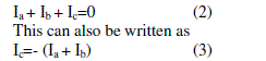 |
| In an ac induction motor drive, at any instant there are always three phase currents flowing as: |
| But from Fig.4, for a BLDC motor (4) is not valid anymore. Due to the characteristics of BLDC motor, only two phases need to be controlled by the four switches using the hysteresis current control method during each operating mode. Hence this scheme is called the Direct Current Controlled PWM scheme [4]. |
| C. Current Regulation. |
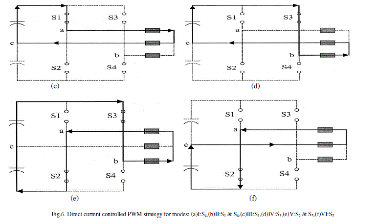
| Current is regulated to obtain the required quasi-square waveform. Based on the switching sequences shown in table I, the current regulation is brought out by hysteresis current control scheme. The switching sequence and corresponding current flow during the six operating modes are depicted in Fig.6. |
 |
| The current regulation and detailed switching sequences are explained in Fig.7.The torque and speed control loop from which the required reference torque is obtained gives the reference current value. This is represented by the bold line. A smaller band causes higher switching frequency and lower toque ripple. Therefore, the upper and lower bands for hysteresis control are fixed based on these values. |
 |
 |
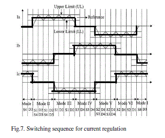 |
| Considering phase A, we can take two cases as follows: |
| Case 1 : Ia>0 |
| Ist Interval : Ia< Lower Limit (LL); S1 is ON |
| IInd Interval : Ia> Upper Limit (UL); S1 is OFF |
| IIIrd Interval : LL<Ia<UL and d/dt (Ia)>0;S1 is ON |
| IVth Interval : LL<Ia<UL and d/dt (Ia)<0;S1 is OFF |
| Case 2 : Ia<0 |
| Ist Interval : Ia >UL; S2 is ON |
| IInd Interval : Ia< (LL); S2 is OFF |
| IIIrd Interval : LL<Ia<UL and d/dt (Ia) <0;S2 is ON |
| IVth Interval : LL<Ia<UL and d/dt (Ia) >0;S2 is OFF |
| The same explanation can be given to phases B and C. |
 |
| D. Back EMF compensation. |
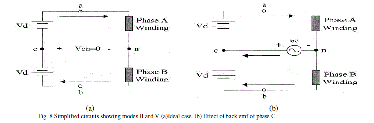
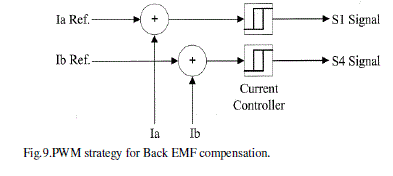
| While examining modes II and V, it’s seen that the active phases are phases A and B and the silent phase is phase C. That means, it’s expected that the current through phase C is zero. But the back emf of phase causes an unexpected current to flow through phase C thereby distorting the actual currents in phases A and B. Therefore, while considering the direct current controlled PWM scheme, the back emf compensation problem should also be considered. Fig.8 illustrates the back emf compensation. In Fig.8 (a), the current through phases A and B are same. Therefore any one current need to be sensed, either the current through phase A or that through phase B. If the current through phase A is sensed, then, the switching signal of S1 is determined independently and that of S4 depends on the S1 signal. So phase A current can be regarded as a constant current source. In this case, the current through phase B will be distorted due to the back emf of phase C. Same is the case when phase B is controlled. Here, the current through phase A would be distorted by the back emf of phase C. From this it’s deduced that the currents through phases A and B should be sensed and controlled independently as shown in Fig.9.This is called Direct Phase Current control scheme (DPC). |
 |
SIMULATION AND EXPERIMENTAL RESULTS |
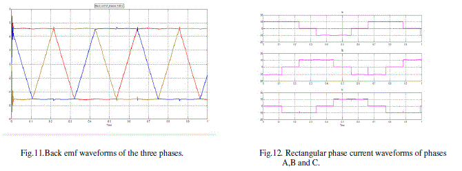
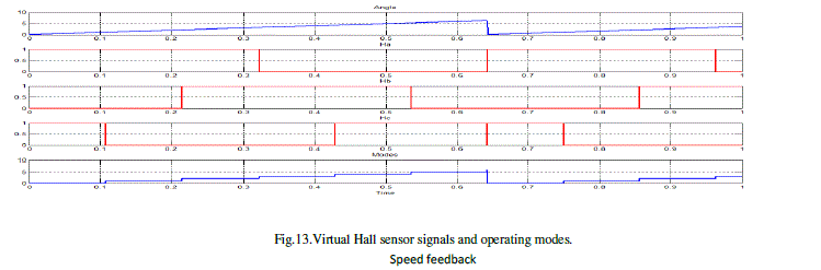
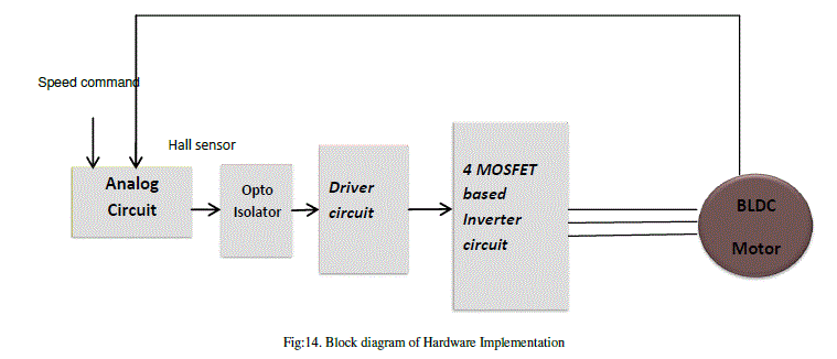
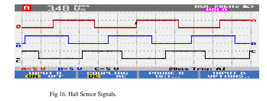
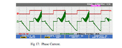
| The implementation of four switch brushless dc motor drive system in simulink [3], [8] is shown in Fig.10. The rated BLDC motor parameters are listed in table II. Fig.11 shows the back emf waveforms of phase A, phase B and phase C. The rectangular phase currents are shown in Fig.12. Fig.13 shows the estimated operation modes and Hall Sensor signals Ha,Hb and Hc. The hardware implementation of the controller circuit of the speed control of BLDC Motor was carried out by using analog circuits. The gating pulses generated by the analog circuit is fed to the Driver circuit through the optocouplers. And finally the output from Driver IC’s are directly given to the 4 MOSFET based inverter circuit. The block diagram for the hardware implementation is as shown in 14.The hardware implementation ste up and test results are shown in figures 15, 16 and 17 |
 |
 |
 |
 |
 |
 |
 |
 |
CONCLUSION |
| A four-switch converter topology is introduced in this paper where cost saving is achieved by reducing the number of inverter power switches. Simulation and hardware results validates the proposed method. The main advantages of the proposed method are: |
| • Simplification of power conversion circuit. |
| • Using four switch inverter, all the six commutation instants can be detected. |
| • This method can be applied to permanent magnet synchronous motors as it is independent of back emf waveforms. |
| Therefore, the implementation of the proposed method is easier and less expensive. |
ACKNOWLEDGMENT |
| The completion of any work brings with it a sense of satisfaction, but it is never complete without thanking those people who made it possible and whose constant support has crowned my efforts with success. . I express my deepest gratitude to Almighty God for holding my hands and guiding us throughout. I would like to express my gratitude to Mrs.Jaya B, Senior Scientist, VSSC, Trivandrum, Dr. George Issac, Principal, Mar Athanasius College of Engineering, Kothamangalam, Head of the Department, Electrical & Electronics and Prof. Radhakrishnan K, our PG coordinator Prof. George John P, for encouraging and inspiring us to carry out the project. I am extremely happy to acknowledge and express my sincere gratitude to my parents for their constant support and encouragement and last but not the least, friends and well wishers for their help and cooperation during the course of project. |
References |
|