I. INTRODUCTION
|
| IN RECENT years, direct torque control (DTC) strategies of induction motor (IM) drives have been widely implemented in industrial variable speed applications. Introduced in the middle of the 1980s, the first DTC strategy involves a simple control scheme which makes it possible rapid real-time implementation. Since then, several investigations carried out in order to improve the performance of the original DTC strategy. The major focused features are the uncontrolled switching frequency of the inverter and the high torque ripple resulting from the use of flux and torque hysteresis controllers. Currently and more than two decades of investigation, several DTC strategies have been proposed so far. These could be classified within four major categories: 1) strategies considering variable hysteresis band controllers; 2) strategies with space vector modulation (SVM)-based control of the switching frequency 3 ) strategies using predictive control. Schemes a n d 4) strategies built around intelligent control approaches. Nevertheless, the gained performance is allied to significant four major categories:1) strategies considering variable hysteresis band controllers; 2) strategies with space vector modulation (SVM)-based control of the switching frequency 3) strategies using predictive control. Schemes a n d 4) strategies built around intelligent control approaches. Nevertheless, the gained performance is allied to significant increase of implementation schemes. Commonly, the voltage source inverter (VSI) feeding IM under DTC is the sixswitch three-phase inverter (SSTPI). This said, some applications such as electric and hybrid propulsion systems should be as reliable as possible. Within this requirement, the reconfiguration of the SSTPI into a four-switch three phase inverter (FSTPI), in case of a switch/leg failure, is currently given an increasing attention. A DTC strategy dedicated to FSTPI-fed IM drives has been proposed. In spite of its simplicity, this strategy is penalized by the low dynamic and the high ripple of the torque. These drawbacks are due to the application of unbalanced voltage vectors to control flux and torque with a subdivision of the Clarke plane limited to four sectors. Recently, an attempt to discard the previously described disadvantages has been proposed in where a DTC scheme using a 16-sector vector selection table has been implemented. Nevertheless, it has been noted that the drive performance remains relatively low due to the increase of the CPU time which is linked to the complexity of the involved vector selection table. In order to achieve a constant switching frequency and to decrease the torque ripple, many DTC schemes based on SVM, using the FSTPI as a VSI, dedicated to control induction and permanent-magnet synchronous motors have been reported in the literature. These strategies offer high performance in terms of torque ripple reduction allied to the control of the inverter switching losses. However, these performances are compromised by the complexity of their implementation schemes. This paper proposes a new DTC strategy dedicated to FSTPI fed IM drives. It is based on the emulation of the SSTPI operation thanks to the synthesis of an appropriate vector selection table, which is addressed by hysteresis controllers. The resulting simplicity of the implementation scheme makes the strategy very attractive in many applications, such as the automotive one. |
II. DTC OF FSTPI-FED IM DRIVES
|
| BACKGROUND |
| A. DTC Basis |
| DTC strategies allow a direct control of the motor variables through an appropriate selection of the inverter control signals, |
 |
| in order to fulfil the requirements as whether the stator flux and torque need to be increased, decreased, or maintained. These decisions are achieved according to the output cφ of the Hysteresis controller and the angular displacement θs of the stator flux vector Fs in the Clarke (aß) plane. The dynamic of Fs is governed by the stator voltage equation expressed in the stationary reference frame, as follows |
 |
| Where Vs, Is, and rs are the stator voltage vector, current vector, and resistance, respectively. Neglecting the voltage drop rsIs across the stator resistance, and taking into account that the voltage vector is constant in each sampling period Ts, the variation of the stator flux vector turns to be proportional to the applied voltage vector. Maintaining the stator flux constant, the variation of the electromagnetic torque Tem depends on the direction of the applied voltage vector, such that: |
 |
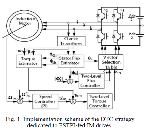
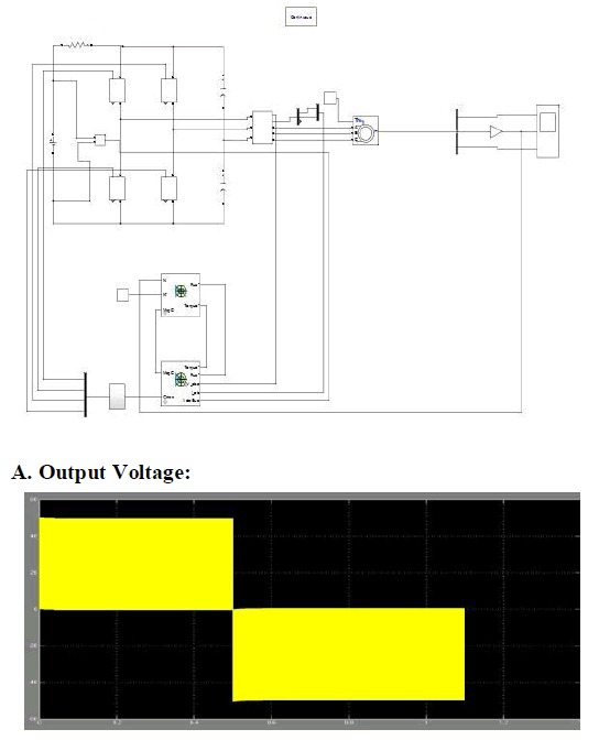
| where F s r is the rotor flux vector referred to the stator, d is the angular shift between the stator and rotor fluxes, Np is the pole pair number, and ls, lr, and M are the stator self-inductance, the rotor selfinductance, and the mutual inductance, respectively. The implementation scheme of the DTC strategy dedicated to a FSTPI-fed IM, shown in Fig.1. |
| 1) The SSTPI inverter is reconfigured to a FSTPI. Such a reconfiguration is carried out by adding to the former three extra TRIACs with three fast acting fuses |
| 2) The three-level hysteresis controller in the torque loop is substituted by a two-level hysteresis controller. As will be depicted in Section III, this substitution is motivated by the fact that no zero voltage vectors is involved in the proposed DTC scheme. |
 |
 |
| B. Intrinsic Voltage Vectors of the FSTPI |
| illustrated in Fig.1. Two among the three phases of the motor are connected to the FSTPI legs, while the third one is connected to the middle point of the dc-bus voltage. |
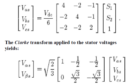
| Let us assume that the states of the four insulated-gate bipolar transistors (IGBTs) of the FSTPI are denoted by the binary variables S1 to S4 , where the binary “1” corresponds to an ON state and the binary “0” indicate an OFF state. The IM stator voltages are expressed in terms of the states (S1 and S2) of the upper IGBTs, as follows: |
 |
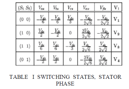
| Four combinations of the states of the upper IGBTs are characterized by four active voltage vectors (V1 to V4) i n the αβ plane, which are given in Table I. |
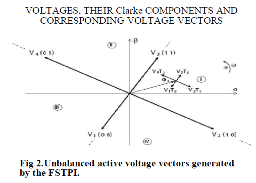
| Fig. 2 shows the four active voltage vectors represented in the αβ plane. These vectors have unbalanced amplitudes and are shifted by an angle of π/2 Indeed, vectors V1 and V3 have |
 |
| C. Limitations of the Basic DTC of a FSTPI-Fed IM |
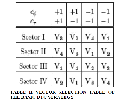
| The basic DTC of an IM fed by the FSTPI is based on the subdivision of the aß plane into four sectors limited by the four active voltage vectors as shown in Fig. 2. The vector selection table corresponding to the basic strategy is presented in Table II. Accounting for the symmetry of the four sectors, the following analysis of the torque and flux variations, will be limited to sector I, considering two cases: |
| 1) The initial stator flux vector Fs1 is held by vector V2; |
| 2) The initial stator flux vector Fs1 is held by vector V3. Equation (1) could be rewritten as follows: |
 |
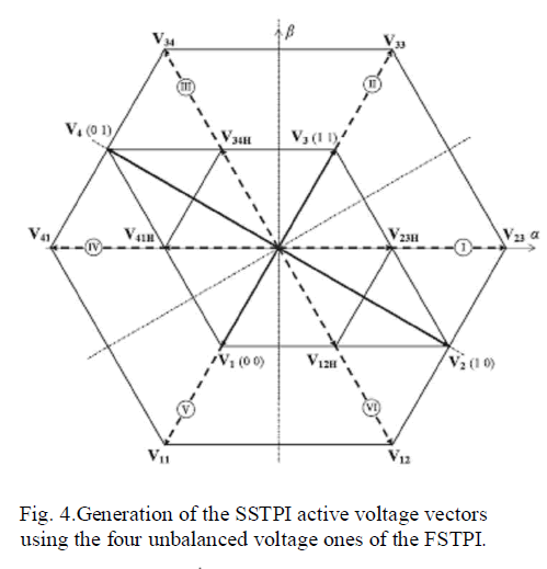
| where Vi (1=i=4) is the voltage vector generated by the FSTPI shows different phasor diagrams of (5), considering both cases previously cited with four scenarios selected from the vector selection table, for each. One can notice the following remarks which deal with the torque dynamic. |
| 1) The application of voltage vectors V1 or V3 leads to a low torque dynamic if: |
| a) Fs1 is close to vector V2 due to the low amplitude of V1 and V3 [see Fig. 3(a1) and (a3)]; |
| b) Fs1 is close to vector V3 due to the low angular shift of the flux vector [see Fig. 3(b1) and (b3)]. It is to be noted that the torque command ct of the control combinations (cf = -1, ct = +1) corresponding to sector II and (cf = +1, ct = +1) corresponding to sector I could not be achieved by the application of vectors V1 and V3, respectively. |
| 2) The application of voltage vectors V2 or V4 leads to a low torque dynamic if Fs1 is close to vector V2 due to |
| the low angular shift of the flux vector [see Fig. 3(a2) and (a4)]. One can notice that the control combinations (cf = +1, ct = +1) corresponding to sector IV and (cf = - 1, ct = +1) corresponding to sector I could not be achieved with the application of voltage vectors V2 and V4, respectively. |
| 3) The application of voltage vectors V2 or V4 leads to a high torque dynamic if Fs1 is located near vector V3 [see Fig. 3(b2) and (b4)]. Concerning the flux dynamic, one can notice the following. |
| 1) High flux variations leading to overshoots or undershoots outside the flux hysteresis band with: |
| a) the application of voltage vectors V1 or V3 if Fs1 is close to vector V3 [see Fig. 3(b1) and (b3)]; |
| b) the application of voltage vectors V2 or V4 if Fs1 is close to vector V2 [see Fig. 3(a2) and (a4)]. |
| 2) The flux command cf is not achieved with the application of: |
| a) vector V1 in sector IV corresponding to the control combination (cf = +1, ct = - 1) as illustrated in |
| b) Vector V2 in sector I corresponding to the control combination (cf = +1, ct =- 1) as illustrated in Fig. |
| c) Vector V3 in sector I corresponding to the control combination (cf = +1, ct = +1) as illustrated in Fig; |
| vector V4 in sector II corresponding to the control combination (cf = +1, ct = +1) as illustrated. From the previous analysis, one can clearly notice that the basic |
| DTC strategy presents different limitations. These could be eradicated considering the introduced DTC |
| d) strategy which will be developed in the following section. |
III. PROPOSED DTC STRATEGY
|
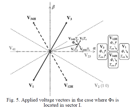
| A. Approach to Generate Balanced Voltages by the FSTPI The proposed DTC strategy is based on the emulation of SSTPI operation by the FSTPI. This has been achieved through the generation of six balanced voltage vectors using the four intrinsic ones of the FSTPI. The generated vectors have the same amplitude and angular shift as those of the SSTPI. Basically, the active voltage vectors Vk, with 1 ≤ k ≤ 6, yielded by the SSTPI have an amplitude Vk equal to _23 Vdc, where Vdc is the dc-bus voltage. For the same value of Vdc, the voltage vectors Vi, with 1 ≤ i ≤ 4, generated by the FSTPI, present unbalanced amplitudes Vi, such that: |
 |
| Therefore, a dual application of the voltage vector V1 (respectively, V3) of the FSTPI, leads to the generation of the voltage vector V11 (respectively, V33), as shown in Fig. 4. It is to be noted that V11 and V33 are identical to two vectors among the six generated by the SSTPI. |
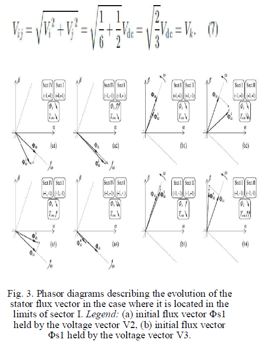
| Now, let us call Vij the voltage vectors resulting from the sums of successive voltage vectors Vi and Vj , with 1 ≤ i ≤ 4 and 1 ≤ j ≤ 4. As far as the angular shift between two successive voltage vectors is equal to π/2 , the amplitude Vij of vectors Vij can be expressed as follows: |
 |
 |
 |
| Applying the generated balanced voltage vectors? To answer this question, the following approach has been adopted. |
| 1) The application of V1 (respectively, V3) during two successive sampling periods 2Ts allows the generation of V11 (respectively, V33) |
| The application of two consecutive voltage vectors VI and Vj during two successive sampling periods leads to the An illustration of the previously described control scenarios is provided in Fig. 6. An extension of the synthesis to the remaining sectors has led to the vector selection table given in Table IV. The inputs (cf, ct, and θs) of the vector selection table should be maintained during 2Ts which yields the implemented vector selection table provided in Table V. It is to be noted that both intrinsic and compounded voltage vectors are involved in sectors III, IV, and VI, while in sectors II and V, only the compounded voltage vectors are applied. Thus, one can expect an increase of the switching frequency in sectors II and V, with respect to the one in the remaining sectors. |
IV. SIMULINK MODEL
|
 |
V. CONCLUSION
|
| This paper dealt with a new DTC strategy dedicated to FSTPI fed IM drives. The proposed DTC strategy is based on the emulation of the operation of the conventional SSTPI. This has been achieved thanks to suitable combinations of the four unbalanced voltage vectors intrinsically generated by the FSTPI, leading to the synthesis of the six balanced voltage vectors yielded by the SSTPI. This approach has been adopted in the design of the vector selection table which is simply addressed by hysteresis controllers, considering a subdivision of the Clarke plane into six sectors. Simulation-based investigations of the IM steady-state features have revealed the high performance of the introduced DTC strategy. These performances have been the subject of an experimental validation along with a comparison against those yielded b y T a k a h a s h i a n d t h e b a s i c D T C s t r a t e g i e s dedicated to the SSTPI and to the FSTPI, respectively |
References
|
- I. Takahashi and T. Noguchi, “A new quick-response and highefficiencycontrol strategy of an induction motor,” IEEE Trans. Ind.Appl., vol. 22, no. 5, pp. 820–827, Sep. 1986.
- Y. Zhang and J. Zhu, “Direct torque control of permanentmagnet synchronous motor with reduced torque ripple andcommutation frequency,” IEEE Trans. Power Electron., vol. 26, no.1, pp. 235–248, Jan. 2011.
- Y. Zhang, J. Zhu, Z. Zhao, W. Xu, and D. G. Dorrell, “Animproved direct torque control for three-level inverter-fed inductionmotor sensor less drive,” IEEE Trans. Power Electron., vol. 27, no.3, pp. 1502–1513, Mar. 2012.
- A. Taheri, A. Rahmati, and S. Kaboli, “Efficiencyimprovement in DTC of six-phase induction machine by adaptivegradient descent of flux,” IEEE Trans. Power Electron., vol. 27, no.3, pp. 1552–1562, Mar. 2012.
- A. B. Jidin, N. R. B. N. Idris, A. H. B. M. Yatim, M. E.Elbuluk, and T. Sutikno, “A wide-speed high torque capabilityutilizing over modulation strategy in DTC of induction machineswith constant switching frequency controller,” IEEE Trans. PowerElectron., vol. 27, no. 5, pp. 2566–2575, May 2012.
- J. K. Kang, D. W. Chung, and S. K. Sul, “Direct torque controlof induction machine with variable amplitude control of flux andtorque hysteresis bands,” in Proc. Int. Elect. Mach. Drives Conf.,Seattle, Washington, May 1999, pp. 640–642.
- K. B. Lee and F. Blaabjerg, “Sensor less DTC-SVM forinduction motor driven by a matrix converter using a parameterestimation strategy,” IEEETrans. Ind. Electron.vol. 55, no. 2, pp.512–521, Feb. 2008.
- Z. Whiffing, T. Renyuyan, B. Boadong, and X. Dexin, “Noveldirect torque control based on space vector modulation with adaptivestator flux observer for induction motors,” IEEE Trans. Magn., vol.48, no. 8, pp. 3133–3136, Aug. 2010.
- J. Beerten, J. Verveckken, and J. Driesen, “Predictive directtorque control for flux and torque ripple reduction,” IEEE Trans. Ind.Electron., vol. 57, no. 1, pp. 404–412, Jan. 2010.
- T. Geyer, “Computationally efficient model predictive directtorque control,” IEEE Trans. Power Electron., vol. 26, no. 10, pp.2804–2816, Oct. 2011.
|