International Journal of Advanced Research in Electrical, Electronics and Instrumentation Engineering
ISSN ONLINE(2278-8875) PRINT (2320-3765)
ISSN ONLINE(2278-8875) PRINT (2320-3765)
Nallamouthu Sairam1 and K.Venkata Naresh2
|
| Related article at Pubmed, Scholar Google |
Visit for more related articles at International Journal of Advanced Research in Electrical, Electronics and Instrumentation Engineering
Ring Laser Gyroscope (RLG) which uses the principle of Sagnac effect is a sensor to sense angular information very precisely. In order to get excellent performance from Ring Laser Gyroscope, Intensity of laser beams, Cavity Path length and also Dithering mechanism needs to be ultra-stable and maintained consistently. Hence control algorithms and hardware is implemented in RLG’s for these three controls. Most of the algorithms implemented are linear and simple in nature. It is felt to use non-linear algorithms based on the dynamics [1] of the RLG to improve performance of an RLG. So in this paper it is proposed to study the principals involved in an RLG control and simulate the dynamics for understanding the non-linarites and finally design new control algorithms for controlling the RLG. MATLAB/Lab VIEW are proposed to be used for realizing these algorithms and finally implement them in DSP. And also this signal processing is emulated in Lab VIEW software and finally implemented on FPGA. This system is used in Missile guidance and control systems, Robotics and Space crafts for tracking, balancing and controlling the motion
Keywords |
| Ring Laser Gyro, Path Length Control, FPGA. |
INTRODUCTION |
| Navigation, Guidance and Control systems both in aircraft and spacecraft require gyroscope to maintain orientation in flight. In particular, the measurement of angular position of a satellite in the space is essential for control and stabilization of its attitude. Systems employing a gyroscope include the control and processing electronics to provide the most direct method for sensing inertial angular velocity. In inertial navigation systems, which uses gyroscopes to measure rate of rotation and acceleration, measurements are integrated once or twice to yield position. Inertial navigation system also has the advantage that they are self-contained. On the downside, inertial sensor data drifts with time because of the need to integrate rate data to yield position; any small constant error increases without bound after integration. Another problem with inertial navigation is the high equipment cost. For example high accurate gyros used in airplanes are prohibitively expensive. Very recently, Laser gyros which are very accurate have become more attractive as alternative solutions because of their lower cost [1]. |
| Since Ring Laser Gyro (RLG) is an important component in modern military navigation systems such as submarine and missiles, its performance level will directly influence the Positioning accuracy in battle. Among the indexes for ranking RLG performance, drift stability and scale factor stability are the most important, which are easily affected by various errors such as temperature effect, environmental magnetic field, frequency stabilization, lock in phenomenon and so on. In order to obtain high performance of RLG, it is necessary to adopt effective measure to minimize the negative errors of those error factors. |
| Among those error factors of RLG, the gain stability of the laser usually tends to be neglected. Most researchers consider that the gain stability is ensured by stabilizing the discharging current of RLG, which is just the traditional method for gain stabilization. In fact, current stabilization doesn’t equal to gain stabilization. Under present level of optical manufacturing techniques, the gain stability is reflected by the stability of total light intensity. By detecting the stability of light intensity in real time, the gain stability could be known. Hence the gain stabilization is actually the light intensity stabilization instead of discharging current stabilization. |
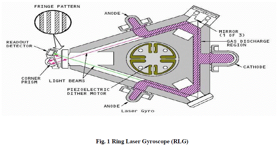
| The RLG operates as resonant cavity. The gas mixture, which sustains the laser, exhibits the gain at certain optical frequencies that excite the stimulated emission, resulting in lasing action. Therefore, the length of the cavity must be tuned to be an integer number of wavelengths. For a helium-neon gas mixture, the wavelength is approximately 630 n meters. Obviously, a cavity whose length is accurate and stable to 1% of a wavelength would be impractical to design. Thus, cavity path length is controlled actively by continuously adjusting mirror positions in order to maximize total laser intensity. Piezoelectric transducers mounted on the back of one or more mirrors induce minute displacement of the mirror faces. In such a way an optimal control algorithm is designed for controlling the path length. |
RING LASER GYROSCOPE |
| The RLG used for this implementation is a 32cm gyroscope. The gaseous medium is the helium-neon mixture corresponding to a wavelength of 0.633μm. Using a square cavity with perimeter of 32cm and for operation at a wavelength of 0.633μm, the scale factor is 0.8162 arc-sec/pulses. The readout techniques use two photo detectors present at a distance of /4 apart in the RLG. To separate the rotation contribution from the high optical frequency, the clockwise and the counter clockwise beams are first made approximately co-linear. Some means of retro- reflecting one of the beams onto the other is used. This results in a fringe pattern with a spacing determined by the degree of co- linearity. When the two fringes are equal, they are stationary in time. When the fringes are different, they move across the field of view at the beat frequency rate Thus by measuring the number of fringes moving across the field of view for a fixed time the count can be obtained. |
 |
| The rotation rate can be determined by using the SF to convert counts to angle which is given by Angle of Rotation = Count × Scale factor (SF). |
| The direction in which the fringes move determines the direction of rotation. To determine this direction, it is customary to use two sensors positioned so that each observes a portion of the figure in quadrature, an offset 90 degrees in phase from the other. Thus both the photo detectors of the figure will detect the same |
RING OUTPUT SIGNALS |
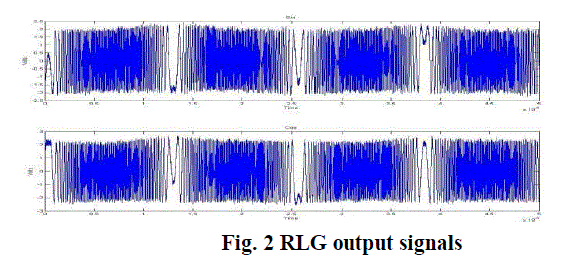
| The two 900 out of phase signals from the photo detectors in the RLG are referred to as the sin/cos signals. The photo detectors produce a signal of 30 μA. A trans impedance amplifier amplifies the photo detector signal to 1V signals which are further amplified by an amplifier card in the RLG to a 5V p-p signal. |
| The sin/cos signals have a frequency range spannig from 10Hz to 1MHz.The sin/cos signals from the photo detectors are frequency modulated by the dither. Thus the signals contain the rotation due to the dither as well as the actual rotation. In order to obtain the count due to the actual rotation the effect of dither has to be removed from the signals. The Fig.2 shows a sample of RLG output signals. |
 |
| The two 90° out of phase signals from the photo detector in the RLG are referred to as the sin/cos signals [7] and further these signals are processed in FPGA which is programmed with the digital path length control algorithm. The platform used is an ML402 evaluation platform that enables designers to investigate and experiment with features of the Virtex-4 family of FPGAs. The Virtex-4 FPGA in ML402 evaluation platform is XC4VSX35-FF668-10[8]. |
PATH LENGTH CONTROL |
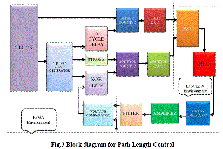 |
A. LAB VIEW ENVIRONMENT |
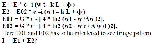
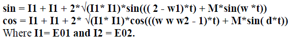
| From the above block diagram there are two environments with which Lab VIEW [9] is used to view the sin/cos signals and from the photo detector they are frequency modulated by the dither. Thus the signals contain the rotation due to the dither as well as the actual rotation. Also CW and CCW beams take the form as follows |
 |
 |
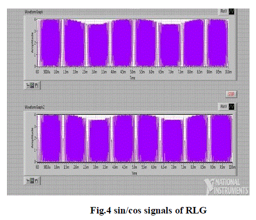 |
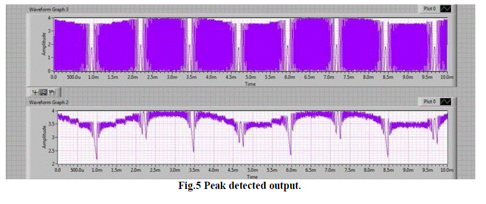
| Therefore these sin/cos signals which are governed by the above equation are peak detected given in Fig.6 and further processed through filter given in Fig.7 which has the following specifications. |
DESGIN OF FILTER |
| The filter is designed in such a way it has |
| Filter type: Band-pass. |
| Cut of frequency Fc1=240Hz and Fc2=260Hz. |
| Sampling Frequency = 2 MHz |
| Order of the Filter = 4 |
 |
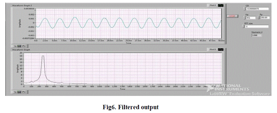 |
| With the designed filter and its generated coefficients, the 250Hz signal is filtered and converted to square wave(digital form) for the signal processing to be done in FPGA. All the signal processing has been done in Lab VIEW and interfaced with FPGA through communication modules for the correction of path length. |
A. FPGA Environment. |
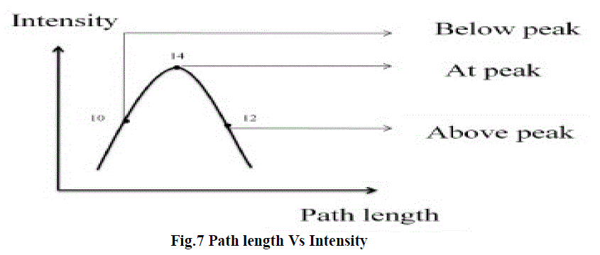
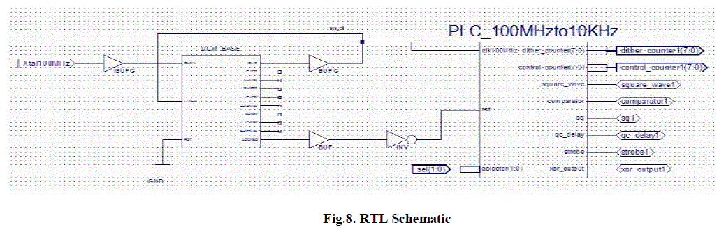
| Now referring to Fig.2 a digital path length control for ring laser gyro comprises a square wave generator, dither counter (driven by the generator with a quarter cycle delay), a dither DAC, a control counter, a control DAC and a PZT driven by the two DAC’s. The PZT controls the path length of the RLG and thus controls the intensity of the light in the gyro. A photo detector samples this light and produces an AC signal, which a voltage comparator compares with ground. The output of the comparator is XORed with the square wave and the output of the XOR gated rives the control counter, strobed with a frequency at least twice that of square wave. All signal processing is digital and analog conversion is made only when interfacing the gyro. This method relates to means for controlling the path length of a ring laser gyro and has a particular relation to such means which areas completely digital as possible. It is apparent that precise control must be maintained over the optical length of the path which the beams take around the ring. The conventional method is analog dithering. Now referring to Fig.3 the intensity of light produced by a laser is schematically plotted as a function of the path length of the RLG. |
 |
B. Method of Controlling the Path length |
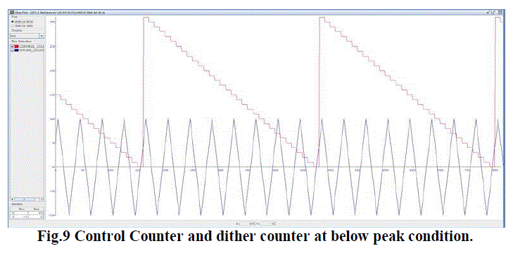
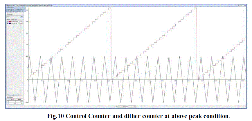
| The path length of an RLG can easily be controlled by controlling the position of one or more mirrors which bounce the laser beam around the ring. This may most conveniently be accomplished by placing piezoelectric transducers (PZT) on the back of the mirror and controlling the thickness of the PZT by controlling the voltage which is fed to the PZT. If the RLG is operating at point 10, then the voltage to the PZT is increased. If the RLG is operating at point 12, the voltage is decreased and if the RLG is operating at point 14, the voltage is kept constant. The PZT is constructed such that increasing the voltage makes the PZT thinner which (PZT is on the back of the mirror) increases the path length. Voltage polarity, PZT position and PZT operation (increased voltage makes it thicker) may be reversed in pairs if convenient. The algorithm for three different conditions has been implemented in Xilinx 13.2iand the signals are viewed in Chip scope Pro Analyzer for three different conditions which are given below for which blue colored signal indicates dither counter and the pink colored signal indicates control counter and RTL Schematic is also given below. |
 |
C. Path Length Correction |
| The path length correction is done in such a way the two counter outputs (analog form) such as dither counter and control counter are obtained and the voltage between the two counters are taken. Here we must understand the fact that the thickness of PZT (and consequent position of mirror controlling the path length of the RLG) does not depend on the absolute or average voltage impressed on its terminals, but on voltage difference between them. Thus, the single PZT responds to the dither DAC and the control DAC. The control counter may be initialized such that the voltage produced by the control DAC is less than the voltage produced by the dither DAC. Thus, when the path length is too short, the XOR gate produces a logic 0. This causes the control counter to decrement (Fig.10), which causes the output voltage of the control DAC to drop and in turn increases the voltage difference between the output of the control DAC and dither DAC. The PZT therefore gets thinner, increasing the path length of RLG, which is the desired result. Provided that the PZT is connected with the correct polarity, the same feedback will occur even when the control DAC produces a voltage greater than that produced by the dither DAC. |
 |
| A similar feedback occurs when the path length is too long which causes voltage produced by the control DAC to increase(Fig.10) and decrease the voltage difference between control DAC and dither DAC. In this case the PZT gets thicker, thereby decreasing the path length which is the desired result in above peak condition. |
 |
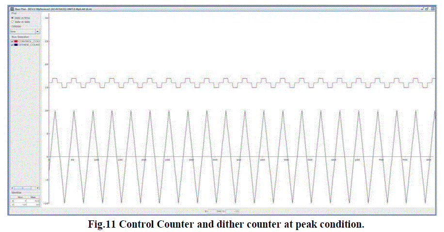 |
| Fig.11 indicates that the voltage difference produced by dither DAC and control DAC will be around zero such that the path length is maintained constant which is at peak. The PZT must be sensitive enough in response to the low voltage dither produced by the dither counter and dither DAC, to produce minor changes in path length needed to drive the intensity up and down the side of the gain curve. Therefore change in path length is considerably less than a wavelength of the laser beam. |
| Let path length given by the equation L = L0 + ΔLCH where L0 is 0.28 and let ΔLCH be the path length correction value. From the above description due to the moment of PZT this ΔLCH can vary from -0.3164 microns to +0.3164 microns and this value is added to L0 for path length correction and finally cavity path length is considerably maintained stable. Thus the voltage difference between these two counters is impressed on PZT terminals and then the necessary path length correction will take place. |
CONCLUSION |
| The objective of improving the performance of the Ring Laser Gyroscope was tackled by developing the control algorithms that will govern the performance of RLG. These three controls such as intensity of laser beams, path length of the cavity and also dithering mechanism are controlled in such a way that they maintain consistently throughout the operation of RLG. Hence control algorithms and hardware are also implemented in RLG fir these three controls. So, in this paper the principals involved in an RLG are studied to control and simulate the dynamics for understanding the non linarites and finally new control algorithms are developed for controlling RLG. MATLAB/Lab VIEW is used for realizing these algorithms and finally implemented in DSP using FPGA Vertex4 Evaluation platform. |
References |
|