ISSN ONLINE(2278-8875) PRINT (2320-3765)
ISSN ONLINE(2278-8875) PRINT (2320-3765)
Bhaskar P.C.1 and Gupta D. K.2
|
| Related article at Pubmed, Scholar Google |
Visit for more related articles at International Journal of Advanced Research in Electrical, Electronics and Instrumentation Engineering
The digital PLL has ability to overcome the drawbacks and performance issues arriving in other controller like fuzzy logic controller, analog PLL and PID controller. So the implementation of digital phase locked loop (DPLL) controller is considering for DC motor speed control. The main emphasis is on the FPGA (Field Programmable Gate Array) implementation of the digital PLL and PWM generator. Digital PLL offer a highly stable frequency controlling than other controller like analog PLL, PID and fuzzy logic controller. The closed loop sensing element is an optical encoder, which outputs an impulse train with a frequency proportional to the motor rotational speed. This impulse train will be synchronized by the Digital PLL to a reference impulse train of a given precise frequency generated inside the FPGA from a quartz crystal oscillator. The phase difference between the two impulse trains is measured by a phase detector by counting pulse width of both the impulses. The phase detector converts the phase difference to a numerical value that can be processed digitally by the loop filter. The loop filter acts as a regulator.DCO (Digital Controlled Oscillator) block of this PLL is replaced by a combination set of Motor and encoder. The DC motor terminal voltages controlled using MOSFET based chopper circuit. The chopper is driven by a précised frequency PWM signal. The result of the project shows that motor speed is not affected so much with the varying loads. On loading the motor speed slow down for about 40 rpm (10%) of its normal speed 400rpm, on unloading the motor speed is hunting to its normal speed 400 rpm. The motor used in this experiment is a DC motor with rated speed of 500 rpm and rated voltage of 12 Volt and rated current of 1 Ampere. Results show the behavior of the designed digital PLL and PWM generator circuits in FPGA.
Keywords |
| FPGA, DPLL, DC motor, Speed controller, PWM generator, Phase frequency detector. |
INTRODUCTION |
| The digital phase-locked loop (DPLL) has better controlling over the analog PLL, PID, fuzzy logic controller etc. and so it provides accurate speed control on loading. DPLL is used in various fields such as communication fields, instrumentation and control fields etc. to escape the drawbacks such as the various types of noise like white noise, spur noise, damping factor, high frequency noise etc. get introducing with linear PLL, it has also poor stability of locking range of frequency so dumping occurs and less efficient for the higher frequencies. Digital PLL controls the speed of DC motors and provides wide locking range. |
| The Digital PLL provides better synchronization for digital signals with help of phase frequency detector and loop filter. |
| Usually, in a DPLL system the phase detector converts the phase difference error to a numerical value that can be processed digitally by the loop filter. The loop filter acts as a regulator, so it provides a control signal value to a digital controlled oscillator (DCO) [7]. |
| The Digital Phase Locked Loop (DPLL) implemented using VHDL code on FPGA (Field Programmable Gate Array) platform. The FPGA is a latest technology in VLSI, which maintaining the advantages of custom functionality like an ASIC while avoiding the high development costs, by using reconfigurable devices, making the testing and prototyping very easy and the in ability to make design modifications after production. If excellent platforms like FPGA have the support of predefined and pre-verified IP cores [8]. Digital PLL is a closed-loop with feedback sub-system, digital signals has to be synchronized. |
| DC Motors controller have been widely using in industrial variable-speed applications because of their desirable speedtorque characteristic and simplicity of control. In some applications the open-loop regulation of the drive motor is adequate. In some others applications feedback control is required for better performance. Conventionally, this is achieved by a servo feedback system in which any change in speed is sensed by the closed loop sensing element is an optical encoder, which outputs an impulse train with a frequency proportional to the motor rotational speed. This feedback impulse train will be synchronized by the digital PLL with a reference impulse train of precise frequency, which generating on the board of FPGA having a quartz crystal oscillator. The phase frequency detector generates a numerical error signal values called as difference error values. |
| The loop filter is called as regulator, which regulates the control signal values as per the difference error values. The control signal values applied to PWM generator as its count values. The PWM generator produces the signal which controls the terminal voltage of DC motor from its duty cycle. The duty cycle of PWM changes as per error signal values produced by phase comparator system [1]. In digital phase-locked loop method, motor speed is converted to a digital pulse train, which is synchronized with a reference digital pulse train. In this way, by locking onto a reference frequency, precise control of motor speed is achieved. |
| To control the speed of DC motors, we are controlling the motor terminal voltages with the help of PWM. The chopper output voltage is proportional to the chopper switching frequency and its duty cycle, so the magnitude of voltages entering the terminal motors can be adjusted, and so the motor speed. This paper presenting an input voltage controlled by MOSFET-chopper, dc motor drive in which digital phase-locked loop principle is applied to precisely synchronize the motor speed to a reference frequency. The DCO is implemented by combination of switching control circuit, MOSFET chopper, dc motor and rotary encoder. |
| An experimental system is accordingly realized to evaluate the motor operation under no-load and full-load conditions. Design procedure is illustrated using actual parameter of a prototype system with a self-excited dc motor (12-V 1000- rpm 1-A) powered from a MOSFET chopper. Finally, implemented and experimental results are given[3]. |
| However, the analog PLL system is not satisfied in working of some applications where excellent speed regulation and fast dynamic response is required. These features can be achieved by using a digital phase-locked loop control system. |
DIGITAL PHASE-LOCKED LOOP |
| Digital Phase-locked loop (DPLL) has been intensively used in control application system where accurate frequency synchronization is required. In its basic blocks of digital phase-locked loop consists of a phase frequency detector (PFD), a loop filter and a digital-controlled oscillator (DCO) as all blocks of PLL are digital so it is called as All digital PLL as shown in Figure1. The DCO output signal is compared with the reference signal by the PFD, which produces an error signal to indicate the phase difference values [4]. |
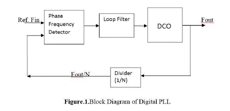 |
| The phase error signal is filtered by the loop filter to providing a control signal value proportional to the phase difference between the two signals. This control signal value is used to vary the DCO frequency in such a direction that reduces the phase difference. An equilibrium state is reaches when the DCO frequency is exactly equal to the frequency of the reference-input signal [3]. |
| By inserting a frequency divider (usually a digital programmable counter) in the feedback path the DCO frequency can be synchronized to a multiple of the reference frequency as shown in Fig. 1. Such a configuration is called a frequency synthesizer, which is usually used to generate precise frequencies in communication systems. |
| The range of frequencies from minimal to maximal value from its reference where the DPLL will remains in the locked condition is called the lock range of the DPLL. If the PLL is initially locked and input signal frequency becomes smaller than fmin, or if input signal frequency exceeds fmax, the PLL fails to keep the it’s rated speed equal to reference input signal frequency, and the PLL becomes unlocked. The digital PLL principle described can be used with advantage in dc motor speed control, providing an effective means to synchronize motor speed to a precise clock signal. The PLL basic configuration or the frequency synthesizer configuration can be used, in which the DCO is replace by the combination of dc motor (with the motor driver) and speed encoder which generated a pulse train of frequency proportional to motor speed. |
FIELD PROGRAMMABLE GATE ARRAY (FPGA) |
| FPGA is a re-programmable chip. A design in FPGA can be automatically converted from gate level into layout structure by place and route software Xilinx ISE offer a wide range of components, for example, XC3S400-4PQ208 offer 30,000 max. Logic-gates on 1000 CLBs (Configured Logic Blocks) with system clock rates up to 4MHz, Designing on FPGA is very fast, easy to modify and suitable for prototyping products, because they are rather expensive and therefore are not economical for mass production[10][7] . |
DESCRIPTION OF THE PROPOSED SYSTEM |
| Digital PLL based DC motor speed control is the proposed speed control system for a self-excited DC motor Powered from an MOSFET chopper is depicted in Fig-2.The system configuration is similar to a phase-locked frequency synthesizer in which the DCO is replace by the combination of switching control circuit, single-phase MOSFET chopper, dc motor, and speed encoder (rotary encoder). The rotary encoder and the programmable divide-by-N counter provide the feedback signal, which is a pulse train of frequency proportional to motor speed. The digital phasefrequency detector is used to compare the feedback signal with a reference pulse train.The detector output is filtered by the low-pass filter to providing a voltage proportional to the phase difference between the two signals. This error voltage is converted into timing pulses for triggering a single-phase MOSFET chopper. Thus the mean motor voltage, and as a result, its speed are consequently varied in order to reduce the phase difference between the feedbacks and reference signals. |
| The block diagram of proposed DC motor speed-control system with master parallel FPGA mode to simplify the circuit is depicted in Figure 2. |
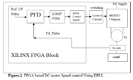 |
| The digital Phase frequency detector, digital loop filter and PWM generator are implemented using behavior and structural model with VHDL in FPGA. When equilibrium-state is reached, the motor speed is precisely synchronized to a multiple of the reference frequency. The digital phase detector and programmable counter design are configured on a single PROM implemented on FPGA XC3S400-4PQ208 with master parallel mode [8][9]. |
• CLOCK DIVIDER |
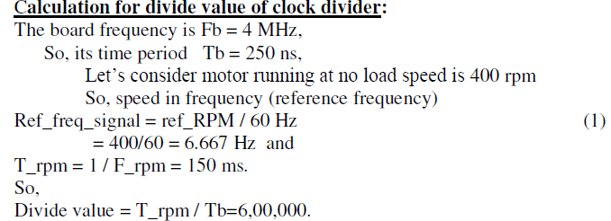
| Clock divider generates reference clock signal corresponding to reference speed of dc motor form crystal frequency of 4MHz of FPGA board. The divide value can be set as count value for clock divider circuit, implemented in FPGA. |
 |
ïÃâ÷ PHASE FREQUENCY DETECTOR |
| The phase-frequency detector is a digital one that implemented on FPGA, which compares the width of reference pulse of trains with feedback pulse of trains width from encoder. The detector output signal value is composed of a dc component and harmonics, which will be eliminated by the loop-filter so that the transfer function of the phase detector can be considered as a constant [1]. |
| So, |
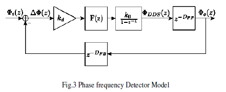 |
| The corresponding phase frequency detector model is shown in Fig. 3. This shows analytical model using Ztransform. |
| The direct digital synthesizer (DDS) is described by the discrete transfer function of the phase accumulator with gain k0. Furthermore, the processing delays (e. g., for pipelining) are included as DFF for the feed forward path and DFB for the feedback path. The DFB is used for small delay variations. For worst-case stability examinations, the maximal group delay has to be used. The gain of the discrete phase detector is named kd. The phase error transfer function can then be obtained by solving equation given below for E(z). |
 |
| The F(z) shows transfer function of filter. The properties of E(z) have to be chosen carefully, For the phase error should tend to zero with increasing time leading to the condition[11]. |
ïÃâ÷ DIGITAL LOOP FILTER |
| The basic function of the loop filter is to produce the control signal value by adding and removing a difference error value from the phase-detector output in order to obtain a regulated signal values which will maintains the speed of DC motor. So loop filter also called as a regulator. |
| So, |
| A proportional-integral (PI) filter is used as the loop filter. This digital filter is described as analytical model of digital loop filter [11]. |
 |
| Where K1 and K2 are the gain coefficients of the proportional and the integral paths respectively. The VHDL model of the loop filter is described behaviorally. When the PFD is initialized with the RESET signal, the output of the loop filter is also set to the initial value as well as the DCO output frequency. Otherwise, the ERROR is processed by the loop filter. |
ïÃâ÷ PWM GENERATOR |
| The PWM duty cycle varies in proportional of difference error value generated by PFD. The voltage supplied to the motor terminals is proportional to the PWM duty, control signal value from loop filter is used as count value for PWM generator. Due to loading on motor speed sensed by encoder is decreases and duty cycle of PWM increases. At No load condition motor running at reference speed of PWM duty cycle 50% [1]. |
ïÃâ÷ DIGITAL CONTROLLED OSCILLATOR (DCO) |
| The Digital Controlled Oscillators in the digital phase-locked loop speed control system is replace by the combination of switching control circuit, MOSFET chopper, dc motor and rotary encoder. The transfer function of the motorencoder block is determined according to as a second order system. |
 |
EXPERIMENTAL RESULTS |
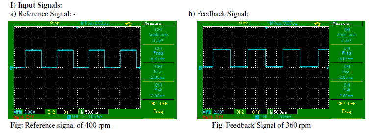
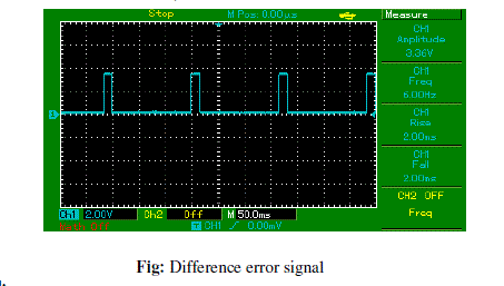
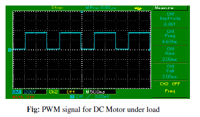
| The experimental results show behavior modeling of the system. As PWM duty cycle varies its average voltage also varies. Here reference signal of 400 rpm, feedback signal of 360 rpm due to load, difference error signal of 40 rpm and corresponding PWM signal waveforms are shown below. PWM duty cycle has 61% ON period and 39% OFF period. |
ïÃâ÷ SIMULATOR BASED RESULT |
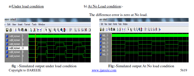
| The model_Sim5.7F generates simulated output of proposed system which similar to actual results under load and at No load condition as follows. |
| a)Under load condition b) At No Load condition:- |
| The difference error is zero at No load. |
 |
ïÃâ÷ HARDWARE BASED RESULT |
| The following waveform shows the input and output signals of real-time proposed system. |
I) Input Signals: |
 |
II) Difference Error Signal |
| At No load condition difference error is zero, but error occurred at load condition as shown in fig. |
 |
III) Output Signal:- |
| a) Under load condition |
| As load is applied to the motor the speed of motor decreases respectively, so to increase speed back to reference speed, duty cycle of PWM increases respectively. |
 |
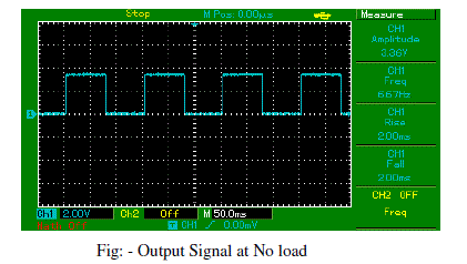
| b) At No Load condition:- |
| As there is no load is applied to the motor the speed of motor same as speed of reference speed having duty cycle of PWM is 50%. |
 |
CONCLUSION |
| An digital PLL (DPLL) controller is highly accurate than other controller like analog PLL,PID ,Fuzzy logic controller to obtain a robust and precise speed control for a DC motor drive has been presented. |
| Conventional speed controller for DC motor system requires a complete mathematical model of the motor. DPLL design uses counter based linguistic description to replace the mathematical model. This can reduce design complexity and expedite the development cycle. However, DPLL control provides best performance for DC motor speed control both in transient state and steady state. The overshoot phenomena may occur due to other control techniques than DPLL depends on the quantization levels of input and output variables. When the speed error is larger, the DPLL becomes active and the system responds quickly by drawing the motor speed into the preset speed error range. The feasibility of using DPLL in DC motor speed control system has been demonstrated. Precise speed regulation is achieved by DPLL operation. It has been shown by experiment that the performance of the system can quickly recover from loss of speed accurately improved than other controller like PID, Fuzzy Logic and analog PLL. |
ACKNOWLEDGEMENT |
| The Satisfaction & emphatic that accompany the successful completion of any task would be incomplete without mentioning the people who made it possible. I am grateful to a number of individuals whose professional guidance & assistance along with the encouragement have made very pleasant, endeavor to undertake this Project. I take this gracious opportunity to express my deep sense of gratitude & appreciation towards our beloved project guide and coordinator Prof. P.C.Bhaskar for his support and precious guidance through my project work. I am also obliged to all teaching and non teaching staff that has directly or indirectly helped me to make this Dissertation Phase-I a great success. |
References |
|