This paper presents hardware architecture for Gray Level Co-occurrence Matrix (GLCM). Texture is one of the important characteristics used in identifying objects or regions of interest in an image. A statistical method of examining texture that considers the spatial relationship of pixels is the GLCM, also known as the gray level spatial dependence matrix. The GLCM functions characterize the texture of an image by calculating how often pairs of pixel with specific values and in a specified spatial relationship occur in an image, creating a GLCM, and then extracting statistical measures from this matrix. GLCM is a second order statistical feature which contains information about pixels having similar gray level values in an image.
Keywords |
| GLCM, FPGA, Texture Analysis, Statistical method. |
INTRODUCTION |
| GLCM represents the distance and angular spatial relationship over an image or image sub-region of specific size.
Gray level co-occurrence matrix, also referred to as a co-occurrence distribution is defined over an image to be the
distribution of co-occurring values at a given offset. GLCM is created from a gray-scale image. GLCM is created from
a gray-scale image. The GLCM contains information about how often a pixel with gray-level (gray scale intensity or
Tone) value i occurs either horizontally, vertically, or diagonally to adjacent pixels with the value j. Where i & j are the
gray level values (tone) in an image. |
RELATED WORK |
| Gray Level Co‐occurrence Matrix is second order statistic measurement that contains information about the positions
of pixels having similar gray level values. Haralick has extracted many statistical features known as Haralick texture
features [1] using the GLCMs. |
| Second-order statistics [2] are defined as the likelihood of observing a pair of gray values occurring at the endpoints of
a dipole (or needle) of random length placed in the image at a random location and orientation. |
| GLCM directions of analysis |
| 1. Horizontal (0˚ or 180˚). |
| 2. Vertical (90˚ or 270˚). |
| 3. Right Diagonal (45˚ or 225˚). |
| 4. Left diagonal (135˚ or 315˚). Denoted as P0, P45, P90 & P135 respectively. |
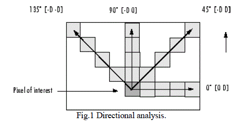 |
| Fig.1 shows directional analysis [3] of P (0°), P (45°), P (90°), P (135°) in an image. If the adjacent pixel to the pixel of
interest is along x axis then it referred to as 0° directional analysis. If the adjacent pixel to the pixel of interest is along
45° then it referred to as 45° directional analysis. If the adjacent pixel to the pixel of interest is along 90° then it
referred to as 90° directional analysis. If the adjacent pixel to the pixel of interest is along 135° then it referred to as 135° directional analysis. For each direction GLCM can be calculated. We can obtain four different GLCM for a same image
or image sub-region. |
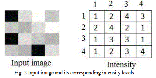
| The following figures explain how to create GLCM for an input image .Consider an input image as shown in figure2
and its corresponding intensity matrix. |
 |
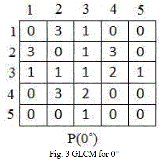
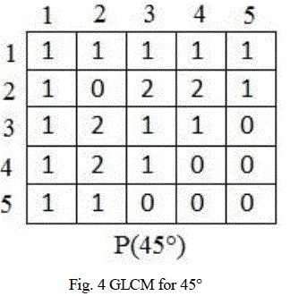
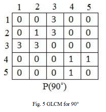
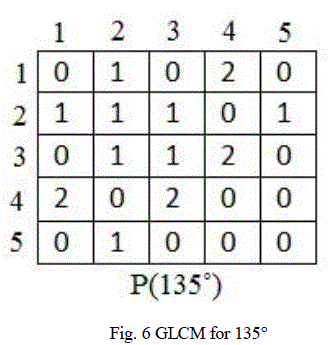
| GLCM is a Ng x Ng matrix, where Ng is the number of gray levels in the input image. Number of pixel pair repetitions
are counted and updated in the GLCM matrix. GLCM can be created for four directions namely 0°, 45°, 90°, 135°. Fig.
3 ,fig. 4,fig. 5, fig. 6 shows GLCM for 0°, 45°, 90°, 135° respectively. |
| Haralick has extracted many properties or features from GLCM. To extract Haralick features GLCM should be a
symmetric and normalized matrix. To make a matrix symmetric, we should take transpose of GLCM and add it with
the original GLCM. To get a normalized matrix, calculate sum of all elements in a GLCM and divide each element of
the matrix with the obtained sum. From the normalized symmetrical GLCM texture features are extracted. |
 |
 |
 |
 |
FPGA IMPLEMENTATION |
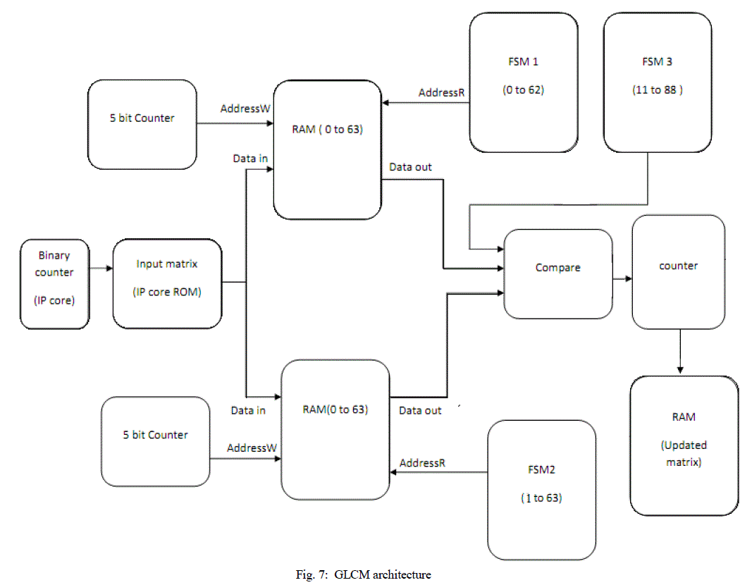
| The block diagram of FPGA implementation of GLCM is as shown in fig. 7. The GLCM architecture was implemented
using Verilog hardware description language. The proposed GLCM architecture is implemented for a 8x8 image (8
tone, that is for images with gray values from 1 to 8). |
 |
RESULTS |
| The GLCM architecture was implemented using Verilog hardware description language (for P (0°)). These descriptions
were then processed by standard Xilinx ISE 10.1 design tool suite, which performed synthesis, placement, routing, and
bit stream (FPGA physical programming information) generation. |
 |
| The bitstream generated was dumped onto XC2VP30 device of Xilinx Virtex 2 pro family. The number of slice flip
flops used was 591 and the number of 4 inputs LUT’s used was 784, each representing 2% of the total resources available. Fig. 8 shows the output of the implemented design seen using chipscope pro. Updated matrix shows the
GLCM, a and b represent location in a matrix, c and d represent the input. |
CONCLUSION |
| In this paper, we have proposed and implemented a novel FPGA based architecture for GLCM. The design was focused
on GLCM hardware realization. The design was completely implemented on hardware. The results obtained were cross
checked with simulation results. |
References |
- S. M. Metev and V. P. Veiko, Laser Assisted Microtechnology, 2nd ed., R. M. Osgood, Jr., Ed. Berlin, R.E. Haralick, K. Shanmugam, I. Dinstein, Textural Features for Image Classification, IEEE Transactions on Systems, Man and Cybernetics, Vol. SMC-3, No. 6, Nov 1973
- Andrea Baraldi and FlavioPanniggiani, An Investigation of the Textural Characteristics Associated with Gray Level Cooccurrence Matrix Statistical Parameters, IEEE transactions on geosciences and remote sensing, vol. 33, no. 2, march 1995
- http://www.mathworks.in/help/images/ref/graycomatrix.html
|