ISSN ONLINE(2278-8875) PRINT (2320-3765)
ISSN ONLINE(2278-8875) PRINT (2320-3765)
DruvaKumar.L1, Jathin.P1, Gowtham.S1 and Manikandan.P2
1druva.kumar@ece.christuniversity.in, 1jathin.p@ece.christuniversity.in,1gowtham.s@cse.christunivesity.in, 2manikandan.p@christuniversity.in |
| Related article at Pubmed, Scholar Google |
Visit for more related articles at International Journal of Advanced Research in Electrical, Electronics and Instrumentation Engineering
This paper puts forth design and functionality of an engine that comprises a dual magnetic piston driven by a pole reversal electromagnet. It introduces eco-friendly magnetic engine into the field of automobiles and motors used generate energy which has high economical efficiency and can substitute the existing petrol and diesel engines. The required equipments are listed and the description of its working is addressed.
Keywords |
| magnetic piston; pole reversal; solenoid; permanent magnet: eco-friendly magnetic engine. |
INTRODUCTION |
| Magnetism is a mysterious force. We can neither see nor feel it. Magnetic engine is the acronym for automobile or a machine which is being moved with the help of magnets. It has a unique combination of two Permanent magnets and an electromagnet. This combination is used for mobile applications. Since the moving parts are minimal, there is a potential for the increase in the system reliability as compared to the existing conventional systems. The primary objective is to construct a highly efficient engine which reproduces the average input energy required for its function by overcoming its losses. Hence the maintenance cost is minimal and simultaneously matching the performance of existing engines. Speaking in regard with the environmental and ecological conditions of today air pollution will be reduced in large scale when implemented worldwide which turns to be a boon for mankind. |
PRINCIPLE |
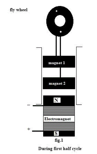
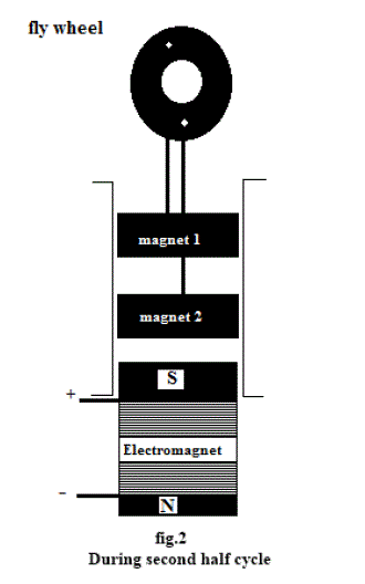
| Magnetic engine works on the basic principle of magnets i.e., like poles repel and unlike poles attract. This phenomenon is achieved with the help of two permanent magnets and an electromagnet placed in certain order as shown in fig.1 and fig.2. |
FUNCTIONALITY OF MAGNETIC ENGINE |
| The initial input to the system is DC which is later converted to AC by using inverters. Initially the engine will be started by supplying current to the electromagnetic setup which is situated at the bottom. Magnetic engine is designed to have two cycles one is the positive half cycle of the input AC and the other is negative half cycle of the input AC. When the current is supplied, the electromagnet produces North Pole at the top and South Pole at the bottom of the solenoid [fig.1]. This North Pole at the top of the electromagnet repels the permanent magnet-2. Permanent Magnet-2 in turn repels the permanent magnet-1. These two permanent magnets are fixed one above the other with South Pole of magnet-2 facing South Pole of magnet 1.Since the magnets are connected to the flywheel, permanent magnets-2 will be alternatively attracted and repelled by the electromagnet while permanent magnet-1 is always repelled by permanent magnet-2. During positive half cycle of the AC input the electromagnet produces North Pole at the top and during negative half cycle; the electromagnet produces South Pole at the top [fig.2]. Hence the reciprocation of the magnets is achieved inside the cylinder. As the two permanent magnets are connected to the flywheel with help of connecting rods, hence the flywheel starts rotating continuously till the input energy to the electromagnet is withdrawn. |
  |
CALCULATION OF MAGNETIC FIELD PRODUCED BY ELECTROMAGNET |
Magnetic field = permeability * turn density*current |
| • Permanent magnets to be used is circular neodymium magnets (B= 4T to 7T). |
| • Core to be used for solenoid is piezoelectric ceramic crystal |
| • Permeability of piezoelectric ceramic crystal used as solenoid (μ0) = 1700 |
| • μ = μ0 μr =2.136283*10-3 |
| • Length of the solenoid (L) =20 cm=0.2m |
| • Number of turns (N) = 500 |
| • Turn density (n) =N/L= 2500 turns/m |
| • Current in the solenoid (I) = 1.32 A |
| • B=μ*n*I |
| • Magnetic field (B) = 7.04 Tesla |
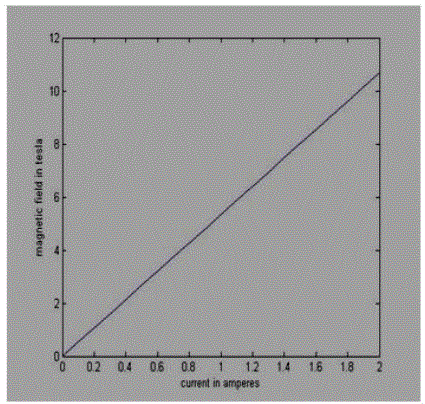
| • MATLAB simulation for the above configuration of electromagnet. |
 |
ANALYSIS OF GRAPH |
| From the above graph, we can notice that magnetic field produce by the electromagnet is mainly depended on number of turns and the input current. As the input current is increased for a constant number of turns the induced magnetic field increases linearly. This shows that input current and number of turns of coil is directly proportional to magnetic field. Hence by varying these two parameters the above magnetic engine can be implemented for different loads. |
APPLICATION |
| • This magnetic engine can be used in robots for specific movements of particular part. |
| • As a source of energy for robots. |
| • This engine can be applied in large industries transport goods from one place to another. |
| • Magnetic engine can be use as a supplement for IC engine in automobiles. |
| • Magnetic engine can be applied in electric current generators instead for hydrocarbon fuel electric current generators [5]. |
| • This engine can be used in wind mills to generate large amount of power [5]. |
CONCLUSION |
| The above magnetic engine is designed for constant load. By changing the configuration of magnets and electromagnets, efficiency of the engine also increases. It is evident that the magnetic engine works without any hydrocarbon fuel as a source; hence this engine is eco friendly. At the present day situation implement of magnetic engine in the place of existing engine, which are used to generate rotational motion or longitudinal movement would reduce the cost in large scale and to reduce pollution. As the amount of current used is generated using solar cell this engine reduces the crisis of hydrocarbon fuel. |
ACKNOWLEDGMENT |
| We wishes to acknowledge department of electronics and communication engineering of Christ University, CUFE, Bangalore, India with their support we are able to prepare this paper. We shall be very thankful for their Warm support and guidance. |
References |
|