ISSN ONLINE(2278-8875) PRINT (2320-3765)
ISSN ONLINE(2278-8875) PRINT (2320-3765)
SANDESH JAIN1, PROF.SHIVENDRA SINGH THAKUR2 and PROF. S.P.PHULAMBRIKAR3
|
| Related article at Pubmed, Scholar Google |
Visit for more related articles at International Journal of Advanced Research in Electrical, Electronics and Instrumentation Engineering
PI controller is very common in the control of DVRs. However, one disadvantage of this conventional controller is its inability to still working well under a wider range of operating conditions. So, as a solution fuzzy controller is proposed. This paper discusses the design and simulation of dynamic voltage restorer for improve power quality and reduce the harmonics distortion of sensitive load. Power quality problem is an occur as a non-standard voltage, current and frequency. Electronics devices are very sensitive load against harmonics. In power system voltage sag, swell, flicker and harmonics are some of the problem to the sensitive load. The compensation capability of a DVR depends primarily on the maximum voltage injection ability and the amount of stored energy available within the restorer. This device is connected in series with the distribution feeder at medium voltage. A fuzzy logic control is proposed. Simulation result carried out by Matlab/Simulink verifies the performance of the proposed method.
Keywords |
| Harmonics, Power quality problem, injection transformer, ESS, VSI, Filter, Fuzzy logic, MATLAB |
INTRODUCTION |
| Power quality problem is an occur as a non-standard voltage, current and frequency. The power quality has serious economic implications for customers, utilities and electrical equipment manufacturers. Modernization and automation of industry involves increasing use of computers, microprocessors and power electronic systems such as adjustable speed drives .The power electronic systems also contribute to power quality problem (generated harmonics). The electronic devices are very sensitive to disturbances and become less tolerant to power quality problems such as voltage sags, swells and harmonics. Due to the harmonics are occurring in the system it causes losses and heating of motor. The dynamic voltage restorer is a custom power device for series connection into a distribution line. When connected in series between a source and a load, the DVR can control the voltage applied to the load by injecting a voltage of arbitrary amplitude, phase and harmonic content into the line. This paper analyses the key issues in the power quality problems, in the proposed system Voltage sag/Voltage swell occurs due to the three phase fault/ground fault/phase to ground fault in the transmission line and harmonics occurs due to the connection of controlled six pulse converter (rectifier) to the main drive load(non linear load). All these factors affect the sensitive load which is connected in parallel to the main drive load. So the proposed system protects the sensitive load by mitigating the harmonics using dynamic voltage restorer technique. |
PROBLEM ASSOCIATED WITH POWER QUALITY |
a. Transients |
| These are undesirable but decay with time and hence not a steady state problem. A broad definition is that a transient is that part of the change in a variable that disappears during transition from one steady state operating condition to the other. Another synonymous term is `surge'. Transients are classified into two categories: (a) Impulsive (b) Oscillatory |
b. Long Duration Voltage Variations |
| When RMS (root mean square) deviations at power frequency last longer than one minute, we say they are long duration voltage variations. They can be either over voltages (greater than 1.1 p.u.) or under voltages (less than 0.9 p. u.). Over voltages is usually the result of switching a load or energizing a capacitor bank. Incorrect tap settings on transformers can also result in over voltages. Under voltages are the result of events which are the reverse of events that cause over voltages switching in a load or switching of a capacitor bank. |
c. Sustained Interruptions |
| When the supply voltage has been zero for a period of time greater than one minute, then we say it is a sustained interruption. Generally, voltage interruptions lasting over one minute are often permanent and require human intervention to restore the supply. The term `outage' used by utilities is synonymous; however it does not bring out the true impact of the power interruption. For a customer with a sensitive load, even an interruption of half a cycle can be disastrous. |
d. Voltage Sags |
| Sag is a decrease of RMS voltage to a value between 0.1 and 0.9 p. u. and lasting for duration between 0.5 cycles to 1 minute. Voltage sags as a voltage dip. Voltage sags are mainly due to system faults and last for durations ranging from 3 cycles to 30 cycles depending on the fault clearing time. It is to be noted that under voltages (lasting over a minute) can be12. Power Quality and Introduction to Custom Power Devices 387handled by voltage regulation equipment. The magnitudes of the voltages sags caused by faults depend upon the distance of the fault location from the bus where the sag is measured. Starting of large induction motors can result in voltage sags as the motor draws a current up to 10 times the full load current during the starting. Also, the power factor of the starting current is generally poor. |
e. Voltage Swells |
| A voltage swell is defined as an increase to between 1.1 and 1.8 p.u.in RMS voltage at the power frequency for duration between 0.5 cycles to 1minute. A voltage swell (like sag) is characterized by its magnitude (RMS) and duration. As with sags, swells are associated with system faults. A SLG fault can result in a voltage swell in the unfaulted phases. Swells can also result from energizing a large capacitor bank. The magnitude of a voltage swell depends on the system impedance, fault location and grounding. On an ungrounded system, the line to ground voltages on the ungrounded phases is 1.73 p. u. during a SLG fault. How-ever in a grounded system, there will be negligible voltage rise on the un-faulted phases close to a substation where the delta connected windings of the transformer (usually connected delta-wye) provide low impendence paths for the zero sequence current during the SLG fault. |
f. Voltage Fluctuations and Flicker |
| Voltage fluctuations are systematic variations of the voltage envelope or a series of random changes in the voltage magnitude (which lies in the range of 0.9 to 1.1 p. u.)High power loads that draw fluctuating current, such as large motor drives and arc furnaces, cause low frequency cyclic voltage variations that result in flickering of light sources (incandescent and fluorescent lamps) which can cause significant physiological discomfort or irritation in human beings. The voltage flicker can also stable operation of electrical and electronic devices such as motors and CRT devices. The typical frequency spectrum of voltage flicker lies in the range from 1 Hz to 30 Hz. |
g. Waveform Distortion |
| This is defined as a steady-state deviation from an ideal sine wave of power frequency. There are five types of waveform distortion: |
| a) DC offset |
| b) Harmonics |
| c) Inter harmonics |
| d) Notching |
| e) Noise |
| The presence of DC voltage or current in AC power systems is termed as DC offset. This can occur as the result of a geomagnetic disturbance or ground return operating mode in mono polar HVDC links. The DC current flow in transformers causes magnetic saturation, increased heating and loss of transformer life. Nonlinear loads and power electronic controllers are the primary source of harmonics. Fourier analysis can be used to characterize harmonic distortion. Total Harmonic Distortion (THD) is one of the most commonly used measures for harmonics. |
Solutions to improve power quality problems and reduce harmonics distortion: |
| The solution to the power quality can be done from customer side or from utility side First approach is called load conditioning, which ensures that the equipment is less sensitive to power disturbances, allowing the operation even under significant voltage distortion. The other solution is to install line conditioning systems that suppress or counteracts the power system disturbances. To achieve improve power quality is to use passive filters connected at the sensitive load terminals. The challenge is to regulate the sensitive load terminal voltage so that its magnitude remains constant and any harmonic distortion is reduced to an acceptable level. This paper introduces Dynamic voltage restorer and its operating principle. Then a simple Fuzzy controller is used to compensate Harmonics, Voltage sag. At the end MATLAB SIMULINK model based simulated results were presented to validate the effectiveness of the proposed control method of Dynamic voltage restorer. |
MODELLING OF DYNAMIC VOLTAGE RESTORER |
Introduction: |
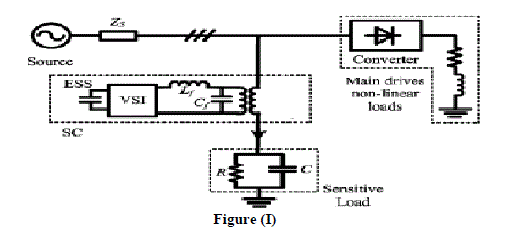
| Among the power quality problems (sags, swells, harmonics…) voltage sags are the most severe disturbances. In order to overcome these problems the concept of custom power devices is introduced recently. One of those devices is the Dynamic Voltage Restorer (DVR), which is the most efficient and effective modern custom power device used in power distribution networks. The function of the DVR will inject the missing voltage in order to regulate the load voltage from any disturbance due to immediate distort of source voltage. A dynamic voltage restorer (DVR) is a solid state inverter based on injection of voltage in series with a power distribution system. The DC side of DVR is connected to an energy source or an energy storage device, while its ac side is connected to the distribution feeder by a three-phase inter facing injection transformer. A single line diagram of a DVR connected power distribution system is shown in the figure (1). Since DVR is a series connected device, the source current, is same as load current. DVR injected voltage in series with line such that the load voltage is maintained at sinusoidal nominal value. It is normally installed in a distribution system between the supply and the critical load feeder at the point of common coupling (PCC). Other than voltage sags and swells compensation, DVR can also added other features like: line voltage harmonics compensation, reduction of transients in voltage and fault current limitations. |
 |
Basic Configuration of DVR: |
| The general configuration of the DVR consists of: |
| a) An Injection/ Booster transformer/Isolation transformer |
| b) A Harmonic filter/Passive filter |
| c) Storage Devices/ESS |
| d) A Voltage Source Converter (VSC)/VSI |
| e) DC charging circuit |
| f) A Control and Protection system |
a. Injection/ Booster transformer/Isolation transformer- |
| The Injection / Booster transformer is a specially designed transformer that attempts to limit the coupling of noise and transient energy from the primary side to the secondary side. In a three-phase system, either three single-phase transformer units or one three phase transformer unit can be used for voltage injection purpose. The injection transformer comprises of two side voltages namely the high voltage side and low voltage side. The three single transformers can be connected with star/open star winding or delta/open star winding. The latter does not permit the injection of the zero sequence voltage. The choice of the injection transformer winding depends on the connections of the step down transformer that feeds the load. If a D/Y connected transformer is used, there is no need to compensate the zero sequence voltages. However if Y/Y connection with neutral grounding is used, the zero sequence voltage may have to be compensated. It is essential to avoid the saturation in the injection transformers. |
| The basic function of the injection transformer is to increase the voltage supplied by the filtered VSI output to the desired level while isolating the DVR circuit from the distribution network. The transformer winding ratio is pre-determined according to the voltage required in the secondary side of the transformer (generally this is kept equal to the supply voltage to allow the DVR to compensate for full voltage sag. A higher transformer winding ratio will increase the primary side current, which will adversely affect the performance of the power electronic devices connected in the VSI. To evaluate the performance of the DVR the rating of the injection transformer is an important factor that need to be considered due to the compensation ability of the DVR is totally depend on its rating .The DVR performance is totally depend on the rating of the injection transformer , since it limits the maximum compensation ability of the DVR. |
b. A Harmonic filter/Passive filter- |
| The passive filters can be placed either on the high voltage side or the converter side of the injection transformers. Basically filter unit consists of inductor (L) and capacitor (C). In DVR, filters are used to convert the inverted PWM waveform into a sinusoidal waveform. This can be achieved by eliminating the unwanted harmonic components generated by the VSI action. Higher orders harmonic components distort the compensated output voltage. The unnecessary switching harmonics generated by the VSI must be removed from the injected voltage waveform in order to maintain an acceptable Total Harmonics Distortion (THD) level. |
c. Storage Devices/ESS |
| This is required to provide active power to the load during deep voltage sags. Lead-acid batteries, flywheel or SMES can be used for energy storage. It is also possible to provide the required power on the DC side of the VSI by an auxiliary bridge converter that is fed from an auxiliary AC supply. The DVR need real power for compensation purpose during voltage disturbance in the distribution system. In this case the real power of the DVR must be supplied by energy storage when the voltage disturbance occurs. The energy storage such as battery is responsible to supply an energy source in D.C form. |
d. A Voltage Source Converter (VSC)/VSI |
| A VSC is a power electronic system consists of a storage device and switching devices, which can generate a sinusoidal voltage at any required frequency, magnitude, and phase angle. In the DVR application, the VSC is used to temporarily replace the supply voltage or to generate the part of the supply voltage which is missing. This could be a 3 phase - 3 wires VSC or 3 phases - 4 wires VSC. The latter permits the injection of zero-sequence voltages. Either a conventional two level converter (Graetz Bridge) or a three level converter is used. There are four main types of switching devices: Metal Oxide Semiconductor Field Effect Transistors (MOSFET), Gate Turn-Off thyristors (GTO), Insulated Gate Bipolar Transistors (IGBT), and Integrated Gate Commutated Thyristors (IGCT). Each type has its own benefits and drawbacks. The IGBT is a recent compact device with enhanced performance and reliability that18 allows building VSC with very large power ratings. Because of the highly sophisticated converter design with IGBTs, the DVR can compensate dips which are beyond the capability of the past DVRs using conventional devices. The purpose of storage devices is to supply the necessary energy to the VSC via a dc link for the generation of injected voltages. The different kinds of energy storage devices are Superconductive magnetic energy storage (SMES), batteries and capacitance. |
e. DC charging circuit |
| The dc charging circuit has two main tasks. |
| (i) The first task is to charge the energy source after a sag compensation event. |
| (ii) The second task is to maintain dc link voltage at the nominal dc link voltage. |
| Excess d.c link voltage rise will damage the d.c storage capacitor and switching device. Moreover the rise in d.c link voltage will nonlinearly increase switching loss and lower the DVR system efficiency. Thus aborting the reverse flow of energy is an important issue that needs to be restored. Many research studies in recent year focused on DVR energy optimization. |
f. A Control system- |
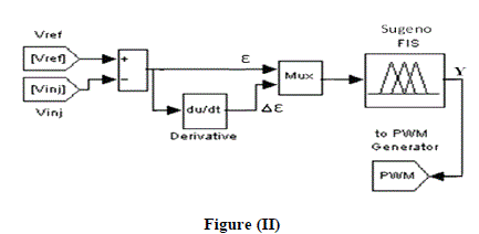 |
| The aim of the control system is to maintain voltage magnitude at the point where a sensitive load is connected, under system disturbances. The harmonics is generated in the load terminals using six pulse converters with fixed firing angle are connected to the main drive non linear load which is parallel to the sensitive load. Voltage sag is created at load terminals via a three phase fault. The above voltage problems are sensed separately and passed through the sequence analyzer. The control system of the general configuration typically consists of a voltage correction method which determines the reference voltage that should be injected by DVR and the VSI control which is in this work consists of PWM with Fuzzy controller. The controller input is an error signal obtained from the reference voltage and the value of the injected voltage. DVR Control strategies fall mainly in one of the two categories namely linear control methods and Non-linear control methods. Linear control methods can be employed with the feedback, the Feed-foreword and the combined feed controllers. Non-Linear control methods comprising the Artificial Neural Networks (ANN), the Fuzzy Logic (FL) and the Space Vector (SV) controllers Although feedback controllers are popular, they Require load and source tracking, whereas feed-foreword controllers are much simpler yet open-looped, there is no Feedback from the load voltage or current. The control of the proposed DVR is based on a fuzzy logic The PWM signal generator that controls the DVR inverter to generate the required injected voltage. |
FUZZY CONTROLLER |
| The performance of Fuzzy logic controller is well documented for improvements of both transient and steady State performances. The function of fuzzy logic controller is very useful since exact mathematical model of it is Not required. The fuzzy logic control system can be divided into four main functional blocks namely Knowledge base, Fuzzification, Inference mechanism and Defuzzification, Rule base. In this study, a fuzzy logic based feedback controller is employed for controlling the voltage injection of the proposed Dynamic Voltage Restorer (DVR). |
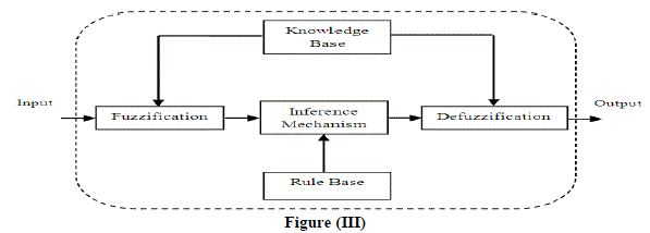 |
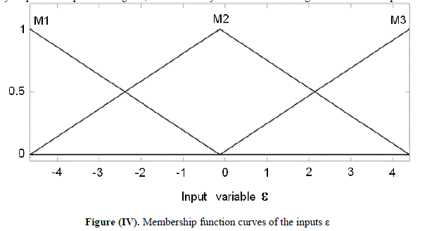
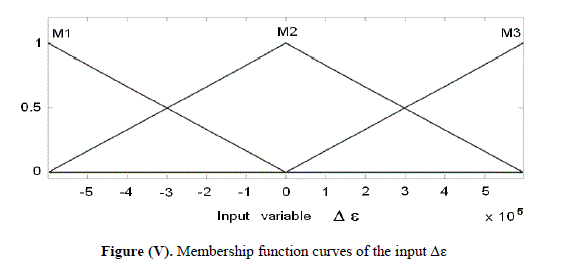
| The knowledge base is composed of data base and rule base. Data base consists of input and output membership functions and provides information for appropriate fuzzification and defuzzification operations. The rule-base consists of a set of linguistic rules relating the fuzzified input variables to the desired control actions. Fuzzification converts a crisp input signal, the error (e), and error change (ïÃÂÃâe) into fuzzified signals that can be identified by level of membership in the fuzzy sets. The inference mechanism uses the collection of linguistic rules to convert the input conditions to fuzzified output. Finally, the defuzzification converts the fuzzy outputs to crisp control signals, which in the system acts as the changes in the control input. |
 |
 |
 |
OPERATION OF DVR |
| Basic operation of DVR is to transfer the voltage sag compensation value from d.c side of the inverter to the injected transformer after filter. The basic idea of DVR is to inject the missing value cycle into the system through series injection transformer whenever voltage sag are present in the system. The momentary amplitudes of the three injected phase voltages are controlled such as to eliminate any detrimental effects of a bus fault to the load voltage VL. This means that any differential voltages caused by transient disturbances in the ac feeder will be compensated by an equivalent voltage generated by the converter and injected on the medium voltage level through the booster transformer. Sag is unseen by the load, during normal operation the capacitor receive energy from the main supply source. When voltage diaper sag capacitor deliver d.c supply to the inverter. The inverter ensures that only the missing voltage injected to the transformer. A relatively small capacitor is present a dc side of the VSI. Voltage of over this capacitor is kept constant. The required output voltage is obtained by using PWM switching pattern. The voltage error and its derivative are the FL controller input crisp values. The reference voltages for the PWM generator are the FL controller crisp output commands. When a FL controller is used, the tracking error and transient overshoots of PWM can be considerably reduced. As the controller will have to supply active as well as reactive power. |
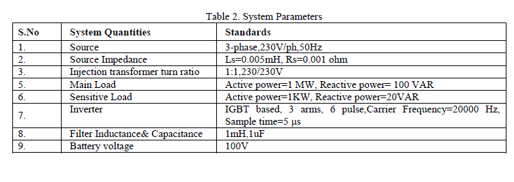
PARAMETER OF DVR TEST SYSTEM |
 |
Simulation Results and Discussions |
 |
HARMONICS’S ISSUES |
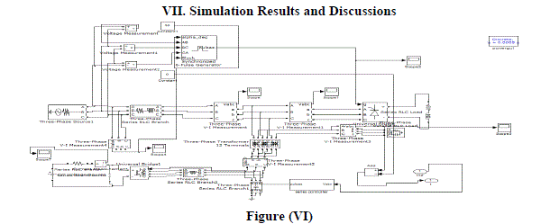
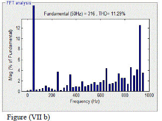
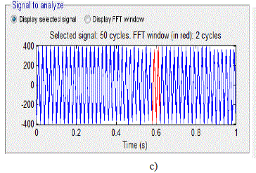
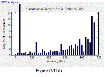
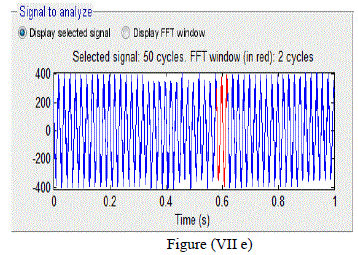
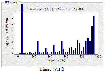
| In simulink model figure (VI) shows the harmonics is generated in the system using six pulse converter connected to the main drive non linear load which is parallel to the sensitive load. The percentage of Total harmonic distortion in the sensitive load side is, in phase1 11.29%, in phase2 15.95%, in phase3 16.70%. In figure (vi) MATLAB simulation is carried out with compensation technique. |
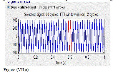
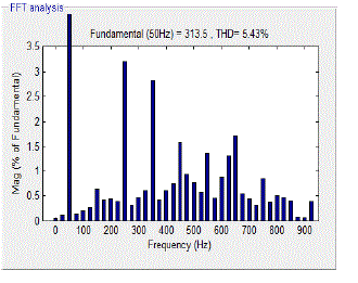
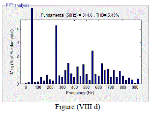
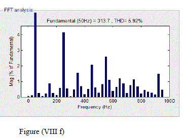
| The percentage of total harmonic distortion in the sensitive load side is, in phase1 5.67%, in phase2 5.56%, in phase3 5.92%. The simulation results show that the harmonics in the sensitive load side is decreased approximately to 50%. The simulation results carried out without series compensator, the harmonics generated are 3, 5, 7, 9, 11, 13, 15, 17,19th harmonics in all three phases. The harmonics distortions produced in all the three phases is shown using FFT analysis in figure (VII), |
 |
 |
 |
 |
 |
 |
| Figure (VII a) output of phase1 harmonics without dynamic voltage restorer. |
| Figure (VII b) THD in harmonics order in phase1 without dynamic voltage restorer. |
| Figure (VII c) output of phase2 harmonics without dynamic voltage restorer. |
| Figure (VII d) THD in harmonics order in phase2 without dynamic voltage restorer. |
| Figure (VII e) output of phase3 harmonics without dynamic voltage restorer. |
| Figure (VII f) THD in harmonics order in phase3 without dynamic voltage restorer. |
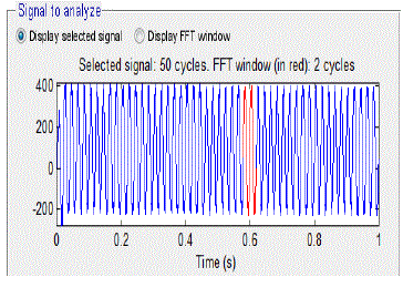
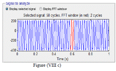
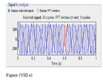
| The simulation results carried out with dynamic voltage restorer generated harmonics are reduced. The reduced harmonics distortions in all the three phases is shown using FFT analysis in Figure (VIII) |
 |
 |
 |
 |
 |
 |
| Figure (VIII a) output of phase1 harmonics with dynamic voltage restorer |
| Figure (VIII b) THD in harmonics order in phase1 with dynamic voltage restorer |
| Figure (VIII c) output of phase2 harmonics with dynamic voltage restorer |
| Figure (VIII d) THD in harmonics order in phase2 with dynamic voltage restorer |
| Figure (VIII e) output of phase3 harmonics with dynamic voltage restorer |
| Figure (VIII f) THD in harmonics order in phase3 with dynamic voltage restorer |
| The following tables show the simulation result carried out with and without using dynamic voltage restorer in Mitigating harmonics. |
 |
 |
| The sensitive load is protected against the distortion introduced by the main drive load and the total harmonic distortion is reduced up to 50%. |
CONCLUSION |
| This paper has presented the power quality problems such as voltage dips, swells, distortions and harmonics. Compensation techniques of custom power electronic devices DVR was presented. The design and applications of DVR for voltage sags and comprehensive results were presented the effective algorithm has been Developed in order to obtain a fast response of the device. The analysis of mitigating harmonics, DVR under fuzzy controller is carried out using MATLAB Power System Block set. The results of simulation are presented and discussed. The THD and the amount of unbalance in load voltage are decreased with the application of DVR. The proposed system performs better than the traditional methods in mitigating harmonics and voltage sags. |
FUTURE SCOPE |
| (a) The application of the model presented in this work may be extended to other power Electronics loads used in modern hi-tech industry. |
| (b) The regenerative power system network consisting of an active load (such as photo voltaic system or wind turbine system) with better power quality and less power Disturbance using DVR can be explored. |
| (c) Investigation of the multi-level of DVR can be investigated. |
ACKNOWLEDGEMENT |
| The authors gratefully acknowledge the Electrical Engineering department, Samrat Ashok Technological Institute, Vidisha, M.P, INDIA for their continued support, encouragement and the facilities provided to carry out this research work. The authors would like to thank my friends and guardian for the moral support to this project. |
References |
|