ISSN ONLINE(2278-8875) PRINT (2320-3765)
ISSN ONLINE(2278-8875) PRINT (2320-3765)
Benazir Hajira A1 Ramya M1 Sathyapriya M1 Anju R1 and Kumar P2
|
| Related article at Pubmed, Scholar Google |
Visit for more related articles at International Journal of Advanced Research in Electrical, Electronics and Instrumentation Engineering
In this paper three phase shunt active filter (SAF) is used to reduction of harmonics in three phase four wire system. The shunt active filter is commonly three independent current controlled voltage source inverter (VSI) with common DC link capacitor. The synchronous reference frame theory (d-q Theory) is used for extracting compensated reference current and Fuzzy Logic Controller (FLC) is used to reduction of load current harmonics. The triggering of gate pulses by using PWM controller and applied to three phase SAF.
Keywords |
| Shunt Active Filter, VSI, d-q Theory, fuzzy logic control, PWM controller. |
INTRODUCTION |
| Early equipment was designed to withstand disturbances such as lightning, short circuits, and sudden overloads without extra expenditure. Current power electronics (PE) prices would be much higher if the equipment was designed with the same robustness. Pollution has been introduced into power systems by nonlinear loads such as transformers and saturated coils; however, perturbation rate has never reached the present levels. Due to its nonlinear characteristics and fast switching, PE creates most of the pollution issues. |
| The objective of the active filtering is to solve these problems by combining with a much-reduced rating of the necessary passive components. Various topologies of active power filters have been developed so far. The shunt active power filter based on current controlled voltage source type PWM converter has been proved to be effective even when the load is highly non-linear. Most of the active filters developed are based on sensing harmonics and reactive volt-ampere requirements of the non-linear load and require complex control. |
| A new scheme has been proposed in, which the required compensating current is determined by sensing load current which is further modified by sensing line currents only. An instantaneous reactive volt-ampere compensator and harmonic suppressor system is proposed without the use of voltage sensors but require complex hardware for current reference generator. Recently, fuzzy logic controllers (FLCs) have generated a good deal of interest in certain applications. |
| The advantages or FLCs over conventional controllers are that they do not need an accurate mathematical model, they can work with imprecise inputs, can handle non-linearity, and they are more robust than conventional nonlinear controllers. In this work fuzzy logic controlled shunt active power filter for the harmonics and reactive power compensation of a nonlinear load are implemented. The control scheme is based on sensing line currents, which are based on sensing harmonics and reactive volt-ampere requirements of the nonlinear load. The three-phase currents/voltages are detected using only two current/voltage sensors. |
LITERATURE REVIEW |
| Suresh mikkili et al.,(2011) proposed commencing with incandescent light bulbs, every load today creates harmonics. Unfortunately, these loads vary with respect to their amount of harmonic content and their response to problems caused by harmonics. The prevalent difficulties with harmonics are voltage and current waveform distortions. In addition, Electronic equipment like computers, battery chargers, electronic ballasts, and variable frequency drives, and switching mode power supplies generate perilous amounts of harmonics. In Mridul jha et al.,(2011) proposed the application of a novel neuro fuzzy based control strategy which is used in order to improve the active power filter dynamics to minimize the harmonics for wide range of variation of load current under various conditions. In M.Bhanu Siva et al.,(2011) proposed method control of three phase 4-wire DSTATCOM consisting of a operating flexibility in the voltage or current control mode. In the voltage control DSTATCOM topology includes three single-phase voltage source converters connected in parallel. The proposed DSTATCOM provides the voltage regulation of power factor correction along with harmonics elimination, load balancing and neutral current compensation in 3-phase - 4 wire system. In Brahim berbaoui et al.,(2011) proposed method the design, analysis and simulation of shunt active power filter which compensate harmonic currents and reactive power under balanced supply network. An optimal control theory for compensation based on particle swarm optimization is developed in this study. |
PROPOSED CONTROL SCHEME |
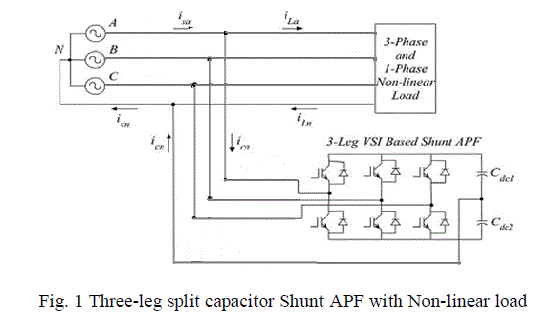
| The basic compensation principle of shunt active filter is controlled to supply compensating current from/to the utility. So that it cancels a current harmonic on the AC side and makes the source current in phase with the source voltage. A shunt active filter is connected to the supply through filter inductances and operates as a closed loop controlled current source shown in fig 1. The output voltage of the inverter is controlled with respect to the voltage at the point of common coupling (PCC). |
 |
A. SYNCHRONOUS REFERENCE FRAME (SRF) |
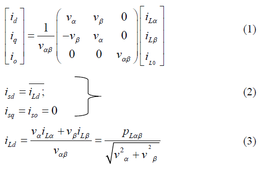
| This method is also known as d-q theory. Here, the reference frame – (direct axis, quadrature axis) is determined by the angle θ with respect to the αβ frame used in the pq theory. The transformation from αβ0 frame to dq0 frame is given by, |
 |
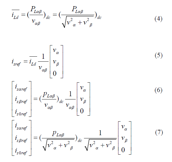 |
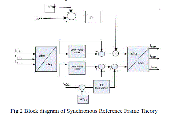
| One of the advantages of this method is that the angle θ is calculated directly from the main voltages, making this method frequency independent. Consequently the synchronizing problems with the unbalanced and distorted conditions of the main voltages are also avoided. Thus with id– iq a large frequency operating limit can be achieved. After the load currents id and iq are obtained from the park transformation, they are allowed to pass through a high pass filter to eliminate the dc components in the nonlinear load currents shown in fig.2. |
 |
B. FUZZY LOGIC CONTROLLER |
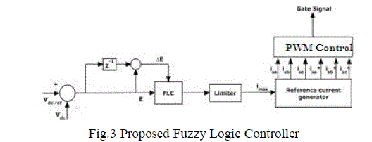
| Fig. 3 shows the internal structure of the control circuit. The control scheme consists of a Fuzzy controller [13], a limiter, and a three phase sine wave generator for the generation of reference currents and switching signals. The peak value of the reference current is estimated by regulating the DC link voltage. The actual capacitor voltage is compared with a set reference value. The error signal is then processed through a Fuzzy controller, which contributes to the zero steady error in tracking the reference current signal. |
 |
| A fuzzy inference system (or fuzzy system) basically consists of a formulation of the mapping from a given input set to an output set using fuzzy logic. This mapping process provides the basis from which the inference or conclusion can be made. A fuzzy inference process consists of the following steps: Step 1: Fuzzification of input variables |
| Step 2: Application of fuzzy operator (AND, OR, NOT) in the IF (antecedent) part of the rule |
| Step 3: Implication from the antecedent to the consequent (THEN part of the rules) |
| Step 4: Aggregation of the consequents across the rules |
| Step 5: Defuzzification |
| The crisp inputs are converted to linguistic variables in fuzzification based on membership function (MF). An MF is a curve that defines how the values of a fuzzy variable in a certain domain are mapped to a membership value μ (or degree of membership) between 0 and 1. A membership function can have different shapes. The simplest and most commonly used MF is the triangular-type, which can be symmetrical or asymmetrical in shape. A trapezoidal MF has the shape of a truncated triangle. Two MFs are built on the Gaussian distribution curve: a simple Gaussian curve and a twosided composite of two different Gaussian distribution curves. The bell MF with a flat top is somewhat different from a Gaussian function. Both Gaussian and bell MFs are smooth and non-zero at all points. |
| The implication step helps to evaluate the consequent part of a rule. There are a number of implication methods in the literature, out of which Mamdani and TS types are frequently used. Mamdani proposed this method which is the most commonly used implication method. In this, the output is truncated at the value based on degree of membership to give the fuzzy output. Takagai-Surgeon-Kang method of implication is different from Mamdani in a way that, the output MFs is only constants or have linear relations with the inputs. |
| The result of the implication and aggregation steps is the fuzzy output which is the union of all the outputs of individual rules that are validated or “fired”. Conversion of this fuzzy output to crisp output is defines as defuzzification. There are many methods of defuzzification out of which Center of Area (COA) and Height method are frequently used. In the COA method (often called the center of gravity method) of defuzzification, the crisp output of particular variable Z is taken to be the geometric center of the output fuzzy value μout(Z) area, where this area is formed by taking the union of all contributions of rules whose degree of fulfillment is greater than zero. |
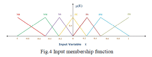
| Here in this scheme, the error e and change of error ce are used as numerical variables from the real system. To convert these numerical variables into linguistic variables, the following seven fuzzy levels or sets are chosen as: NB (negative big), NM (negative medium), NS (negative small), ZE (zero), PS (positive small), PM (positive medium), and PB (positive big). |
| The fuzzy controller is characterized as follows: |
| • Seven fuzzy sets for each input and output. |
| • Triangular membership functions for simplicity. |
| • Fuzzification using continuous universe of discourse. |
| • Implication using Mamdani's 'min' operator. |
| • Defuzzification using the 'height' method. |
| The control scheme consists of a Fuzzy controller, a limiter, and a three phase sine wave generator for the generation of the internal structure of the control circuit. The control scheme consists of a Fuzzy controller, a limiter, and a three phase sine wave generator for the generation of reference currents and switching signals. The peak value of the reference current is estimated by regulating the DC link voltage. The actual capacitor voltage is compared with a set reference value. The error signal is then processed through a Fuzzy controller, which contributes to the zero steady error in tracking the reference current signal. |
| A fuzzy controller converts a linguistic control strategy into an automatic control strategy, and fuzzy rules are constructed either by expert experience or with a knowledge database. Firstly, the input Error ‘E’ and the change in Error ‘4E’ have been placed with the angular velocity to be used as the input variables of the fuzzy logic controller. Then the output variable of the fuzzy logic controller is presented by the control Current Imax. To convert these numerical variables into linguistic variables, the following seven fuzzy levels or sets are chosen: NB (negative big), NM (negative medium), NS (negative small), ZE (zero), PS (positive small), PM (positive medium), and PB (positive big), as can be seen in Fig.4. |
 |
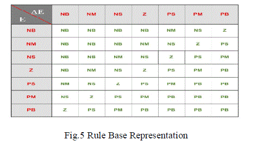
| Rule Base: The elements of this rule base table are determined based on the theory that in the transient state, large errors need coarse control, which requires coarse input/output variables, while in the steady state, small errors need fine control, which requires fine input/output variables. Based on this, the elements of the rule table are obtained as shown in Fig.5. |
 |
C. PWM CURRENT CONTROLLER |
| In a current controller, the sensed source currents (isa, isb, isc) and reference source currents (isa*, isb*, isc*) are compared and a proportional controller is used for amplifying current error in each phase. Then, the amplified current error is compared with a triangular carrier signal of switching frequency to generate the gating signals for six IGBT switches of VSI of SAPF. The gate signals are PWM controlled so that sensed source currents follows the reference source currents precisely. |
SIMULATION AND RESULT |
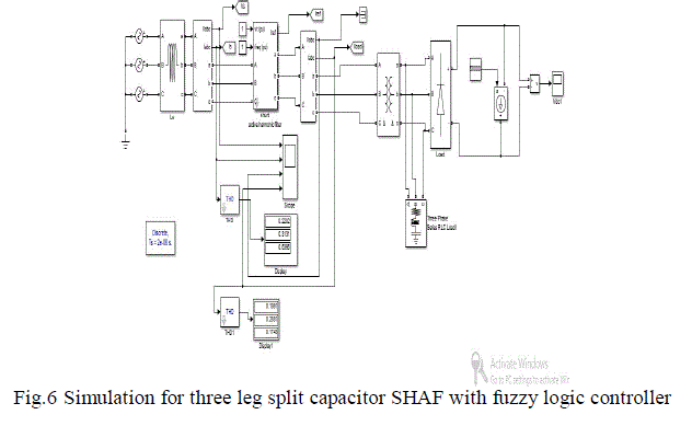
| The Fig-6 shows the overall block of the system consists of source, load and shunt active power filter. The supply is given through the 3-phase source and load is of non-linear type. Here the load considered is three phase diode rectifier, which is of simple and reliable to control. The transformer is connected between the source and load in order to sense the voltage and current at source level. |
 |
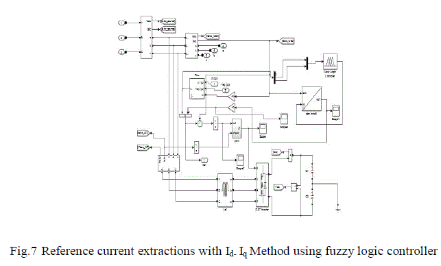 |
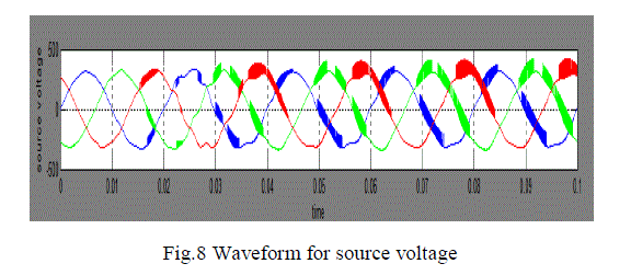
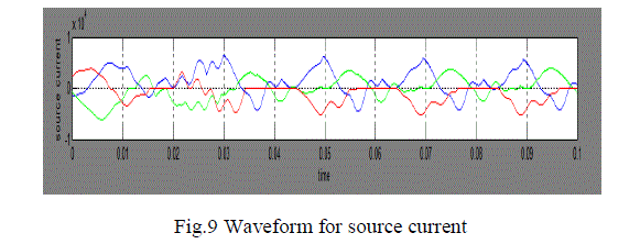
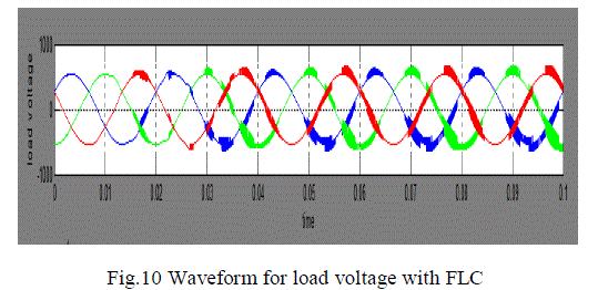
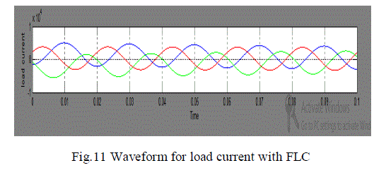
| Fig-7 shows the process of shunt active power filter with fuzzy logic controller unit. The main aim is to maintain the dc link voltage as constant and load current as sinusoidal. This achieved through fuzzy logic controller unit; in this error value and change in error value of load current is measured and compared with each other. Based on this result control signal is generated from the filter circuit to the load. Each and every time the value of load and source current, voltage are sensed. These sensed values are plotted in the Fig-8 to Fig-11. |
 |
 |
 |
 |
CONCLUSION |
| In this work fuzzy logic controller was developed and verified for three phase four wire systems. Even though PI controllers are capable of compensating current harmonics in 3 phase 4-wire systems, it can be seen that the Fuzzy Logic controller has a better dynamic performance than the conventional PI controller. PWM pattern generation based on carrier less hysteresis current control is used for quick response. Additionally, in contrast to the different control strategies; the idiq method is used for obtaining the reference currents in the system. This is due to the fact that the angle‘θ’is calculated directly from the main voltage which enables an operation which is frequency independent. As a result, this technique avoids large number of synchronization problems. It can also be seen that the DC voltage regulation system is a stable and steady-state error free system. Thus with fuzzy logic and the (id-iq) approach, a novel shunt active filter can be developed. Simulation results are presented to validate the performance of the shunt active filter. |
References |
|