INTRODUCTION
|
| The GeoZigBee wristwatch device was designed specifically to provide an ultra low-power, miniaturized wireless GPS tracking device. It includes a low-power GPS sensor, a flash memory and a ZigBee® wireless data link. The design of the device was selected to minimize the power drain to allow operation for extended periods of time. The power savings is accomplished by remoting the GPS signal processing from the sensor to the LocatorNet server. This has the advantage of minimizing the power drain within the GeoZigBee device while allowing sophisticated signal processing to be performed at the server to maximize the sensitivity of the GPS signal processing solution. The design of the GeoZigBee device is included in this paper. |
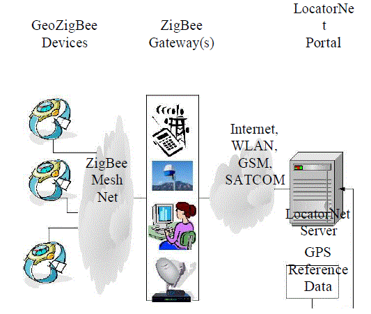
| The networked system architecture for relaying data between the tracking devices and the LocatorNet Server is illustrated in Figure 1. The ZigBee devices are programmed to search for a ZigBee gateway that provides a connection to the Internet. Once a Gateway is found, the devices upload their GPS sensor data through the Gateway to the LocatorNet Portal for processing. This paper describes the LocatorNet system architecture and the design of the ZigBee Gateways. The ZigBee Gateways have been developed to be an add-on to a standard PC providing a low-cost, secure method of connecting ZigBee to the Portal through a variety of physical network connections including wired Ethernet for fixed connections or WLAN, cellular or SATCOM services for mobile units. |
| The LocatorNet Server provides the data processing to convert the GPS sensor data into locations. The design of the Software Defined Radio (SDR) used for processing the GeoZigBee GPS data is described in this paper and test results are included demonstrating the system operation. The LocatorNet Server is integrated with a Web Portal that allows users to access the sensor location data for analysis and display. This web-based architecture allows the common infrastructure to be leveraged by a variety of different users. Some example applications are described in this paper. |
II. TIDGET GPS SENSOR
|
| The patented TIDGET® (“tracking widget”) sensor operates by taking brief snapshots of GPS data when activated[1]. These snapshots are stored in the flash memory and forwarded to the LocatorNet Server through the data link for processing[2]. |
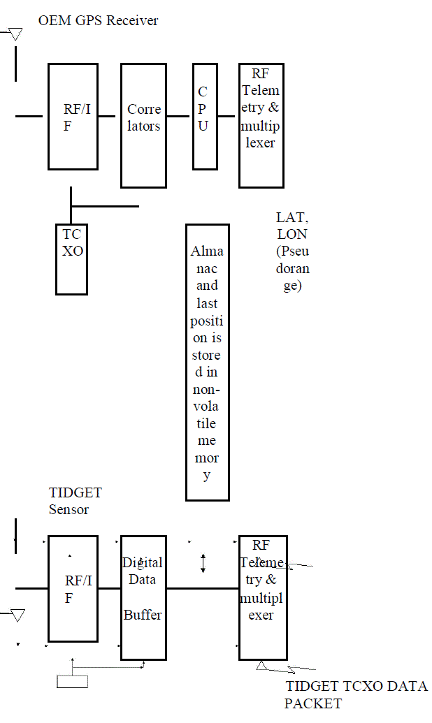
| The TIDGET is built using the RF front-end of a commercial GPS chip (see Figure 2). The device is designed to operate with a variety of different types of data links providing a low-power location solution. Instead of performing the GPS signal processing using an internal baseband processor, the TIDGET device only samples and records the GPS snapshots periodically. While this requires more data to be transmitted across the wireless data link, it significantly reduces the overall power drain of the device making this an ideal solution for low-power tracking applications. |
| Figure 2 TIDGET Sensor |
| The TIDGET can be programmed to take different sizes of GPS snapshots depending on the application. The larger the snapshot, the greater the ability of the LocatorNet processing to track low-power GPS satellite signals[3]. For the GeoZigBee device, a 36.4 kbyte snapshot size was selected. This allows GPS signals to be detected to a C/N0 of 26 dB-Hz (-148 dBm) with a SNR detection threshold of 10 dB. When multiple satellites are in view, enhanced signal processing can be used to detect weak signals as low as 20 dB below the strongest GPS satellite signal, down to a threshold of -156 dBm. This signal tracking performance is comparable with a state of the art GPS chip set such as the SiRFstarIII[4]. |
| This chip set is capable of acquiring GPS signals to a threshold of -147 dBm indoors when using aiding data from GSM, 3G, or CDMA and when one satellite is being received at -147 dBm. The SiRFstar III is able to compute an aided open sky fix using only 100 mJ of power. However, under weak signal conditions the power/fix increases to over 1350 mJ. The TIDGET power consumption by comparison remains constant at 15 mJ for taking a 52 msec (36.4 kbyte) snapshot whether strong or weak signal processing is needed to be performed at the Server |
| The total power consumption of the TIDGET device must also include the data link required to transmit the TIDGET data back to the LocatorNet Portal. In Table 1, a list of some of the different wireless data links that could be used for transmitting this data are included. For the low-power GeoZigBee wristwatch application, we have selected the ZigBee data link as providing the best compromise in terms of power consumption, range of operation and data bandwidth. |
| Table 1 Alternative TIDGET Data Links |
ZIGBEE DATA LINK
|
| ZigBee[5] is a low-power wireless mesh networking protocol that has been designed for maximum power life. The GeoZigBee wristwatch device includes a ZigBee data link that can be used to connect to a ZigBee Gateway when within range. A networking protocol has been developed that allows the ZigBee wireless data link to transport the data to the Gateway where it is forwarded to the GeoZigBee Server for processing. |
| Basic ZigBee’s initial market profile is for lighting, HVAC, and security systems, all very low-bandwidth applications. ZigBee has built in mesh networking allowing single or multi-hop connections between units to a Gateway. Using the basic ZigBee “reliable mode” of transmission, we were only getting 32Kbps throughput for a single hop connection and only 2Kbps to 3Kbps throughput, with 6-7% packet loss, on a 2 hop (3 node) network. This performance was not sufficient for prompt, reliable wireless uploads of the GeoZigBee data to a Gateway. To address this issue, we developed an applicationlayer selective retransmission protocol, built on top of the ZigBee best-effort mode. This protocol is more intelligent and provides true network reliability resulting in increased data throughput. With a single hop network, we sustained over 90Kbs, and in many cases, with good signal strength, we could obtain nearly 200Kbps, all with zero packet loss and very few retransmissions. For a two hop network we maintained over 45Kbps with 3% to 5% retransmissions needed to ensure zero overall packet loss6. |
| An important factor to consider is that this throughput performance improvement was achieved without any changes to the actual ZigBee Protocol by developing an application layer enhancement on top of the existing protocol. This way the proprietary part of any ZigBee Stack need not be altered. Since the enhancement will run on the application layer, it could be included in the ZigBee profile as a utility |
| The normal range of operation of the ZigBee data link, using onboard or PCB Antennas, is within 100 feet of a Gateway. A Gateway can be a conventional PC equipped with a ZigBee USB device and installed with the LocatorNet network upload software. While straight ZigBee dongles exist, the system design uses a GeoZigBee unit configured in a “gateway mode” connected by USB to the PC. The LocatorNet network upload software converts the GeoZigBee data into a sequence of Database update commands and sends those over a TCP/IP connection to the Portal. |
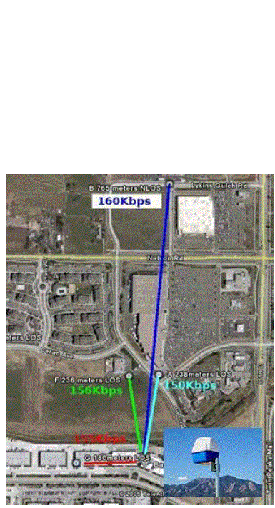
| The range between the GeoZigBee device and the ZigBee gateway can be extended by adding an improved antenna to the ZigBee Gateway. Static directional antennas on both the node and the coordinator can improve the operational distance by a factor of 4-10, but are unacceptable for the watch unit. Larger amplified directional antennas, such as that shown in Figure 3, have allowed us to extend the high-bandwidth single-hop transmissions up to 765m, while only using the onboard PCB antenna for the GeoZigBee node The Phased Array antenna shown in Figure 3 also provides a Linux-based network router making it ideal for a Gateway unit. |
GEOZIGBEE DEVICE
|
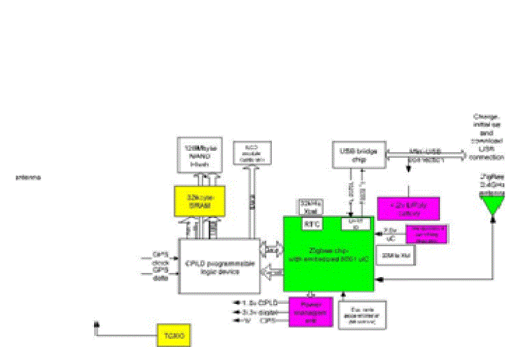
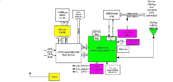
| As depicted in Figure 4, the GeoZigBee wristwatch unit comprises a ZigBee chip with an embedded microcontroller, a "glue-logic" CPLD programmable logic device, GPS cache SRAM, bulk-storage Flash memory, a GPS front-end RF chip, antenna and TCXO, a USB interface chip and power management circuitry. |
| The host microcontroller acts as system controller, spending most of its time in a very low- power powerdown mode (16uA, 166 Joules/month), with programmed wake-up by timed events from its onboard Real-Time Clock. On periodic wake up, it checks for available connections to ZigBee Gateways and takes GPS snapshots. To minimize wasting memory, if the device is not oriented to the sky, an onboard dual axis accelerometer can estimate orientation. |
| If a GPS snapshot is requested, the GPS front-end circuitry will be powered on and the GPS data streamed via the CPLD to an SRAM cache memory. The GPS section is then immediately powered down. The host uC will then copy the memory from SRAM to the Flash file system |
| The microcontroller extensively controls power management of the device, only powering up the sections of the circuit that are needed at the appropriate time. Power is supplied by means of an onboard 140mAhr Lithium Polymer cell. This cell is charge via the wrist watch USB connection. The USB connection also gives a means to initialize the device and an alternative means of downloading stored data |
| Each captured GPS snapshot requires 15mJ to acquire under all circumstances. To transmit the data to the gateway, the circuit will consume between 70mJ and 231mJ per snapshot depending on range and signal environment. Total battery energy available to the device is 2000 Joule. |
LOCATORNET PORTAL
|
| The locatorNet portal is based on an Oracle Application server.The ZigBee gateway software is designed to “publish” data into the LocatorNet Portal which initiates a data processing sequence using the LocatorNet Server signal processing software. The locator net server is implemented using an SDR architecture where the GPS signal generation and code correlation functions are performed in software. The GPS Navigation data is loaded into the LocatortNet Portal from reference station sites across the Internet allowing world-wide tracking of GPS data. The LocatorNet Portal also can access digital terrain data allowing altitude-aided solutions to be calculated in the event that only three GPS satellites are tracked. Using a special purpose high speed signal processor, the time-to-compute-fix (TTCF) for the TIDGET data is less than 200 msecs. With a Pentium 4 processor the TTCF is approximately 1 minute. |
| The LocatorNet Portal provides a secure repository for the GeoZigBee tracking data allowing only authorized subscribers access to individual GeoZigBee device results. A Web-based interface is provided to display the data results overlaid on a map. |
| implemented using an SDR architecture where the GPS signal generation and code correlation functions are performed in software. The GPS Navigation data is loaded into the LocatortNet Portal from reference station sites across the Internet allowing world-wide tracking of GPS data. The LocatorNet Portal also can access digital terrain data allowing altitudeaided solutions to be calculated in the event that only three GPS satellites are tracked. Using a special purpose high speed signal processor, the time-to-compute-fix (TTCF) for the TIDGET data is less than 200 msecs. With a Pentium 4 processor the TTCF is approximately 1 minute. |
| The LocatorNet Portal provides a secure repository for the GeoZigBee tracking data allowing only authorized subscribers access to individual GeoZigBee device results. A Web-based interface is provided to display the data results overlaid on a map. |
III. TEST RESULTS
|
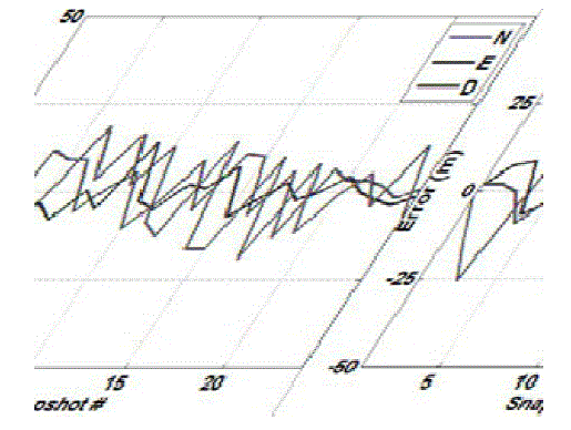
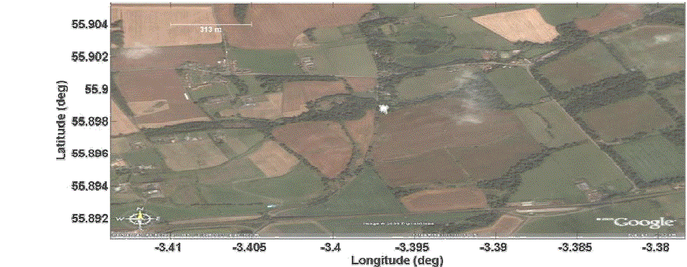
| To demonstrate the GeoZigBee tracking performance, representative data was collected from a stationary reference location. Figure 5 illustrates the navigation accuracy associated with the snapshot signal processing. Here, the data positions were compared to the reference position. The position differences are illustrated in a standard North, East, Down coordinate frame for the first 24 snapshots. A measured CEP of 5.14 m was demonstrated with this data. Figure 6 plots the navigation position solutions on a local satellite photo. The cluster of white points near the image center visually demonstrates the precision of the solutions. |
IV. CONCLUSION
|
| The first GeoZigBee system is being developed for the U.S. Army TATRC for use in clinical trials. Its initial use is envisioned as a hospital type bracelet that will be used to collect the location and time of treatment applied to trauma patients in support of clinical trials. The data presented in this paper is from a lab GeoZigBee unit. Delivery of the first wristwatch prototype units will occur in early 2007. |
| The GeoZigBee units have the following advantages over previous GPS tracking solutions. |
| • Ultra low-power design enabling operation for 30 days using a wristwatch size device and battery |
| • Wireless networked connectivity using low-cost COTS ZigBee devices |
| • Improved ZigBee data transfer reliability using an enhanced ZigBee transmission protocol |
| • Secure data management for maintaining privacy and managing access to GeoZigBee tracking data |
| • Web-based access and display of the GeoZigBee tracking results |
| Commercial, military and government applications are envisioned for the GeoZigBee tracking technology. The inexpensive, small GeoZigBee devices can be used for monitoring locations of children, pets, parolees or Alzheimer patients as examples. By the Subscriber defining a “Perimeter” at the LocatorNet Portal, automated web services can be used to alert the subscriber when the designated device passes beyond that perimeter. Applications also exist for First Responders. In many emergency response or disaster recovery scenarios, there is a need to maintain situational awareness on the location of emergency personnel. By placing an extended range ZigBee Gateway (see Figure 3) on an aircraft, the locations of emergency responders on the ground can be routed to the LocatorNet Server and made available to the First Responder command centers through the Internet. This type of system would have immediate benefit for providing realtime situational awareness of personnel in hazardous areas. By overlaying the GeoZigBee personnel locations on a realtime mosaic provided by a system such as NAVSYS’ GI-Eye and GRIM7 products, First Responders would have real-time knowledge of personnel located in danger areas such as fire hot spots or flood zones as in the Hurricane Katrina scenario |
| NAVSYS is currently working with industry partners who are interested in producing and distributing the GeoZigBee devices for a variety of commercial applications. |
| V. ACKNOWLEDGMENTS |
| The authors would like to acknowledge the support of Dr. Gary Gilbert and TATRC who have provided funding to support the development of this technology. |
Tables at a glance
|
 |
| Table 1 |
|
| |
Figures at a glance
|
 |
 |
 |
 |
| Figure 1 |
Figure 2 |
Figure 3 |
Figure 4 |
 |
 |
 |
| Figure 5 |
Figure 6 |
Figure 7 |
|
| |
References
|
- A. Brown, “The TIDGET – A Low Cost GPS Sensor for Tracking Applications”, ION 5th International Technical Meeting, Albuquerque, September1992
- GPS tracking system, United States Patent 5,379,224
- A. Brown, M. May, B. Tanju, “Benefits of Software GPS Receivers for Enhanced Signal Processing”, GPS Solutions 4(1), Summer, 2000 pp 56-66
- http://www.sirf.com/Downloads/Collateral/GSC3(f)_6.20.05.pdf
- ZigBee Specification v1.0, ZigBee Document 053473r00, Version 1.00, ZigBee Alliance dated December 14, 2004.
- Sujeeth Narayan, “Extension of Zigbee stack to achieve higher reliability and throughput for transfer of large data objects”, MS Thesis U. Colorado atColorado Springs, 2006
- A. Brown, H. Holland and Y. Lu, “Real-Time Web-based Image Distribution using an airborne GPS/inertial Image Server”, ION GNSS 2006, FortWorth, September 2006
|