ISSN ONLINE(2278-8875) PRINT (2320-3765)
ISSN ONLINE(2278-8875) PRINT (2320-3765)
B.Paranthagan1, M.Marimuthu1 and M.Karthiga2
|
| Related article at Pubmed, Scholar Google |
Visit for more related articles at International Journal of Advanced Research in Electrical, Electronics and Instrumentation Engineering
The performance of a photovoltaic (PV) array is affected by temperature, solar insolation, shading and array configuration. The PV system exhibits a non-linear I-V characteristic and its unique maximum power point on the P-V curve varies with insolation and temperature. Often the PV array gets shadowed, completely or partially, by passing clouds, neighbouring buildings and trees. This situation is of particular interest in case of large PV installations such as those used in a distributed power generation scheme and residential PV systems. Under partially shaded conditions, the P-V characteristic becomes more complex with multiple peaks. Conventional Maximum Power Point Tracking (MPPT) techniques fail to reach global peak power point and tend to stay in local peak power point which significantly reduces the efficiency of the PV system. This paper mainly focuses on extracting the maximum power from PV array under partially shaded conditions by executing improved hill climbing algorithm to identify the global maximum power point (GMPP) and SEPIC is used as a dc-dc interface. Simulation results have been presented to verify the performance of the proposed GMPPT technique.
Keywords |
| Maximum power point tracking (MPPT), Hill climbing algorithm, Photovoltaic I-V characteristics, Global Maximum Power Point (GMPP) |
INTRODUCTION |
| With a Spurt in the use of non-conventional energy sources, Photovoltaic installations are being increasingly employed in several applications. However a major challenge in using a PV source is to tackle its nonlinear output characteristics which vary with temperature and solar insolation. The characteristics gets more complicated if the entire array does not receive uniform insolation as in partially shaded conditions resulting in several multiple peaks. This reduces the effectiveness of the existing maximum power point schemes due to their inability to differentiate between the local peaks and global peak[5]. Nevertheless, it is very important to understand and predict the P-V characteristics of PV array to use a PV installation effectively under all conditions. When the individual modules or cells of a PV panel have non-uniform current generated due to variation in irradiation (i.e partial shading) known as “mismatch condition”, the overall PV characteristics may present multiple peaks. The global MPP occurring at a low voltage level and local MPP being placed at a voltage quite close to that one at which the unique MPP normally occurs in the uniform irradiation case makes it difficult to directly apply the gradient based MPPT control algorithms. |
| In [1], the technique proposed consists of a two-stage MPPT along with Voc and Isc measurement. Though it is very simple to apply, additional circuits are required to measure Voc and Isc. In [2], MPPT based on P&O in addition to a subroutine called Global Peak(GP) subroutine was proposed. Though this does not require any additional circuit, it guarantees tracking the global peak power point only when multiple peak power points happen to be on the similar power level. In [3], MPPT method proposed is based on particle swarm optimisation(PSO). This technique has good performance under various mismatching conditions. Main drawback of this method is that the algorithm is so complex that many variables of PSO method can be set only by engineer. So, a simple solution is the sweeping search by Hill climbing algorithm across full operating voltage using sufficiently dense searching which often leads to long search time[4]. Hence, in this modified Hill climbing algorithm, global searching is carried out using large change in duty cycle, D just to find out different peak power points evolving on the P-V characteristics of the PV array and then local searching is done with small change in duty cycle, D only in the region of Global MPP so that search time is considerably reduced. |
SYSTEM DESCRIPTION |
| This section describes the details of the PV system and design of the converter with MPPT. |
A. DESCRIPTION OF BASIC BLOCK DIAGRAM |
| Basic block diagram of PV maximum power point tracking system implemented using SEPIC converter is shown Fig.1. |
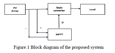 |
| System load is supplied from the solar system which consists of four PV modules connected in series. Maximum power is extracted from the PV system using SEPIC converter by controlling the duty cycle, D with the help of MPPT controller. As in most of the MPPT controllers, PV voltage Vpv and current Ipv are measured to implement the global MPPT algorithm. |
B . DESIGN OF SEPIC CONVERTER |
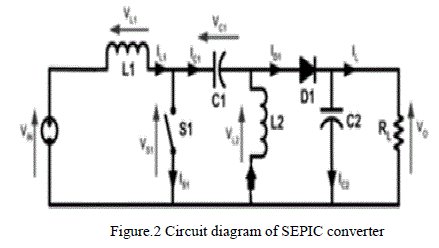
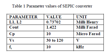
| The SEPIC converter is used as an interface between the PV array and the load to provide load impedance matching with the PV source. SEPIC is essentially a boost converter followed by buck-boost converter. Therefore SEPIC is similar to buck-boost converter but it has the advantage of having non- inverted output. Also the coupling capacitor offers isolation between output side and input side which is unique to SEPIC converter only. In SEPIC converter, MPP tracking can be done with ease because of low input ripple current. In addition to that, SEPIC converter is more efficient than buck-boost converter. The circuit diagram of the SEPIC converter is shown below. The design of SEPIC converter has been explained and the designed values of the different parameters of the SEPIC converter is listed in the table 1. The SEPIC converter is designed for 920 W load since four panels are connected in series as each panel is rated for 230 W peak power. Unlike uniform irradiation condition where unique MPP occurs at a voltage close to 0.75Voc, peak power points occur at lower, middle and higher voltage levels of the PV array. |
 |
| The following equations are used to design the SEPIC converter. |
 |
 |
C. MODEL OF PV SYSTEM |
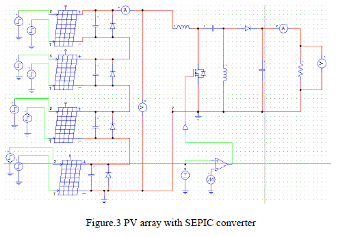
| To simulate the PV system, PV model available in the PSIM 9.0.3 version has been made use of and four such PV modules are connected in series and then connected to the SEPIC converter as shown in the Fig.3. The by-pass diode is connected across each panel so that panel is protected from getting damaged due to mismatching irradiation. The datasheet parameter values of the PV module used in this simulation are given in the table 2. |
 |
 |
IMPORTANCE OF MAXIMUM POWER POINT TRACKING |
| The penetration of PV systems as distributed power generation systems has been increased dramatically in the last years. In parallel with this, Maximum Power Point Tracking (MPPT) is becoming more and more important as the amount of energy produced by PV systems is increasing. Since the MPP depends on solar irradiation and cell temperature, it is never constant over time and hence Maximum Power Point Tracking (MPPT) technique should be used to track the maximum power point. |
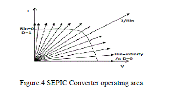 |
| It was mentioned earlier that the range of operation of SEPIC converter covers the entire V-I characteristics of the PV cell/module as shown in fig.4 and hence it is a suitable converter to be picked for MPPT under normal as well as partially shaded conditions. In general, maximum power is transferred to the load from the source only when the impedances of the load and source are matched. If the load is connected directly to the PV system, the impedance matching may not occur at all operating conditions. Therefore, SEPIC converter is used as an interface to provide the impedance matching. The equation which relates the load resistance and input resistance of the converter in terms of duty cycle D is given in equation 5 |
| Rin= (1-D)2/D2 × R0 |
| By varying duty cycle, entire P-V curve can be swept using SEPIC converter which is very much essential for tracking global maximum power point under partial shading conditions. |
EFFECTS OF PARTIAL SHADING CONDITION ON THE PV ARRAY |
A. CHARACTERISTICS OF P-V CURVE UNDER PSC |
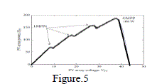
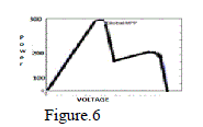
| A PV array usually consists of several PV modules which are connected in series-parallel to obtain the desired voltage and current. Bypass diodes are used in parallel with each PV module to protect modules from hot-spot problems. When the solar irradiance is uniform, only one MPP exists on the P-V characteristic curve. But under non-uniform irradiation (partial shading) conditions, several local maximum power points evolve on the P-V characteristic curve. Fig.5 shows the P-V characteristic of a partially shaded PV array when they receive the irradiation as 800 W/m2, 200 W/m2, 200 W/m2, 800 W/m2 from top to bottom with respect to Fig.3. Similarly Fig.6 and Fig.7 show P-V characteristic curve for 800 W/m2, 600 W/m2, 400 W/m2 ,200 W/m2 and 800 W/m2,500 W/m2,300 W/m2,200 W/m2 irradiations respectively. |
 |
 |
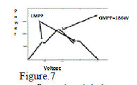 |
| Fig.5, fig.6 and fig.7 show that there are several peaks that exist on the P-V curve. In fig.5, the global MPP occurs at a voltage quite close to that one at which the unique MPP normally occurs in the uniform irradiation case. In fig.6, global MPP occurs at a low voltage level and the local MPP occurs at a voltage quite close to that one at which the unique MPP normally occurs. In fig.7, global MPP occurs at middle voltage level. This global MPP happens to be in between two local MPPs. Therefore, partial shading has a strong impact on the P-V characteristic curve of the PV system. |
B. FAILUR OF CONVENTIONAL MPPTS |
| The mostly used MPPT techniques (P & O method, Incremental Conductance method, RCC method etc) work very well under uniform irradiation conditions. They track the maximum power point efficiently because there exists only one MPP on the P-V characteristic curve. But under partial shaded conditions, there exists several MPPs on the P-V curve as explained in the previous section. In addition to that, global MPP occurs at different voltage levels. Therefore, conventional MPPT methods fail to track the global MPP and instead they tend to stay at a local MPP which occurs at a voltage quite close to that one at which the unique MPP normally occurs in the uniform irradiation case. |
PROPOSED GLOBAL MPPT ALGORITHM |
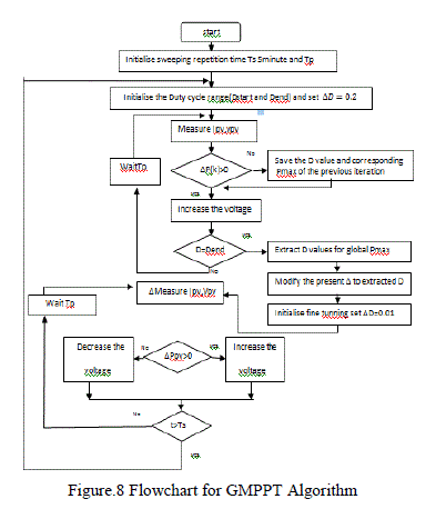
| The global MPPT methods implemented so far fail to reach the global MPP when global MPP occurs in between two local MPPs as shown in fig.7. Therefore, the proposed algorithm has been developed such that it tracks global MPP under any operating condition under two stages. |
| (i) Global search with a large step size, Δd |
| (ii) Local search with a small step size, Δd in the region of global MPP |
| The proposed MPPT algorithm is based on the hill climbing method. The improved hill climbing algorithm sweeps the majority of the entire P-V curve with a large step size in duty cycle, Δd in the search space set between the Dstart and Dend so that no maximum power point is missed during the entire search. During the search started from Dstart, whenever the sign of difference in power, ΔP(k)=P(k) – P(k-1) , changes from positive to negative, it indicates that there exist a maximum power point in the region corresponding to the duty cycle D(k-1) and D(k). Therefore, corresponding duty cycle that represents the starting point of the region D(k-1) and corresponding power P(k-1) are stored. Then the search is continued until the duty cycle D is equal to Dend. During the rest of the search also, Duty cycles D and corresponding powers P with respect to other maximum power points are also stored in a similar manner. Once the global search is over, then global MPP is identified from the stored values of all the maximum power points just by comparing the powers P of each duty cycle, D. since the step size Δd used for the global search is sufficiently large enough, time taken to finish the entire global search is reduced. The global maximum power point identified by the global search will not transfer the actual maximum power available under the given weather conditions because global MPP identified by the global search is near to the actual global MPP. Therefore to reach the exact global MPP, local search is started now with starting duty cycle as D(k-1) with small step size in duty cycle, Δd. once the exact global MPP is reached, there will be a twostep oscillation around the global MPP. Since the step size Δd is very small, the magnitude of oscillation around the global MPP is reduced so that the efficiency of the PV system is increased. According to this algorithm, global search is repeated every five minutes as weather conditions may have changed. |
 |
SIMULATION RESULTS |
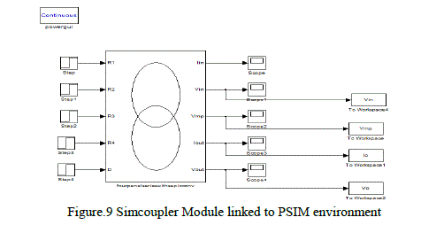
| Simulation of the proposed system is carried out in MATLAB/SIMULINK environment coupled to PSIM through simcoupler module. For implementing the hill climbing algorithm, programming has been developed using MATLAB and executed after linking this program with SIMULINK. The PV system with SEPIC converter is simulated in the PSIM environment and linked to the SIMULINK environment with the help of simcoupler. |
 |
| Figure.10,Figure.11 and Figure.12 show the simulation results for different partial shading conditions given in the table 3 |
 |
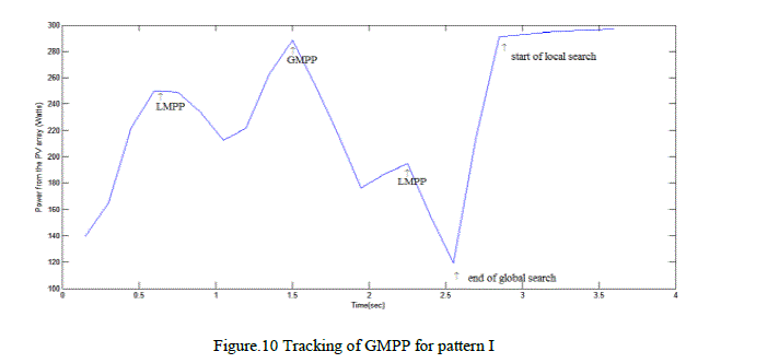 |
| The simulation result shown in fig.10 has two local MPPs and one GMPP in the middle. Under this kind of P-V curve of PV array, other GMPPT methods fail to reach the GMPP. But the GMPP technique proposed in this paper identified global MPP through global search and has settled at the GMPP through local search at steady state |
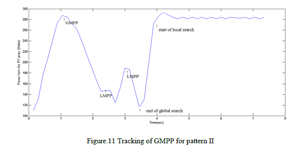 |
| In fig.11, first GMPP occurs and then two local MPPs occur consecutively. In this kind of P-V curve of the PV array corresponding to pattern II too, GMPP has been identified exactly by global search and the PV system settled at this power level through local search. But, conventional MPPTs usually tend to stay at one of the local MPPs and hence leads to huge power loss. |
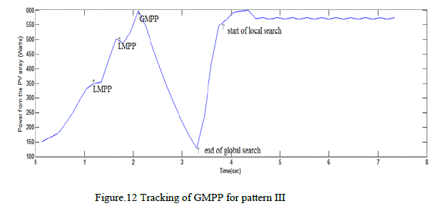 |
| P-V curve of the PV array has been simulated for pattern III and shown in fig.12. In this case, two local MPPs evolve first followed by a global MPP. Global search exactly identified the GMPP and the PV system has settled at this power level. In all these cases, the global search has been completed within reasonable time because of large step size used for duty cycle. |
 |
| In fig. 13, steady state part of the fig.12 has been expanded to show that the steady state losses caused by oscillation of the PV operating point around the GMPP because of small change in duty cycle adopted during the local search. The magnitude of oscillation is less than 1% of the average power level around GMPP. |
CONCLUSION |
| Simulation was done in the MATLAB/SIMULINK environment coupled to PSIM software for different partial shading conditions. The simulation results show that the improved hill climbing algorithm identifies the global maximum power point within reasonable time without missing any local maximum power points through global search as the step size for duty cycle is large enough. Then local search exactly reaches the global maximum power point with minimum oscillations as the step size is very small. Therefore search time as well as magnitude of oscillations around global MPP are reduced significantly thus improving the tracking efficiency and overall system efficiency. |
References |
|