INTRODUCTION
|
| Stripline filters play an important role in many RF applications. As technologies advances, more stringent requirements of filters are required. One of the requirements is the compactness of filters . At very high frequencies, the practical inductors and capacitors loses their intrinsic characteristics. Also a limited range of component values are available from the manufacturer. Therefore for microwave frequencies (>3GHz), passive filter is usually realized using distributed circuit elements such as transmission line sections. Many works have been reported that use waveguides for transmission line filter. However, waveguides systems are bulky and expensive. Low-power and cheaper alternatives are stripline and microstrip. These transmission lines are compact. Edge-coupled stripline is used instead of microstrip line as stripline does not suffer from dispersion and its propagation mode is pure TEM mode. Hence it is the preferred structured for coupled-line filters. Therefore, a third order chebyshev edge-coupled stripline filter is designed in the research. |
BASIC THEORY
|
PARALLEL-COUPLED,HALF-WAVELENGTH RESONATORS FILTERS
|
| Figure 2.1 illustrates a general structure of parallel-coupled (or edge-coupled); microstrip bandpass filters that use halfwavelength line resonators. They are positioned so that adjacent resonators are parallel to each other along half of their length. This parallel arrangement gives relatively large coupling for a given spacing between resonators, and thus, this filter structure is particularly convenient for constructing filters having a wider bandwidth as compared to the structure for the end-coupled microstrip filters. |
| The design equations for this type of filter are given by |
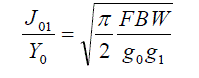 |
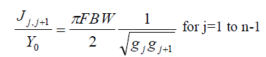 |
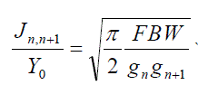 |
| where g0, g1… gn are the element of a ladder-type low-pass prototype with a Normalized cutoff Ωc = 1, and FBW is the fractional bandwidth of band-pass filter. J j, j+1 are the characteristic admittances of J-inverters and Y0 is the characteristic admittance of the terminating lines. The equation above will be use in end-coupled line filter because the both types of filter can have the same low-pass network representation. However, the implementation will be different. |
| To realize the J-inverters obtaine |
 |
DESIGN METHODOLOGY
|
| Given a center frequency of 2.45 GHz, bandwidth of 10% and equal ripple in the pass-band of 0.5dB and 30dB design a band-pass filter for the ISM band with 3rd order Coupled Line configuration for the given specification. Use FR4 and Roger Ro4003c substrate of dielectric constant 4.2 with thickness of 1.58mm and 3.38 and 3.38mm respectively. Refer to the filter tables given in D.M Pozar [2] to find the following coefficients for 0.5dB and 30dB ripple third order Chebyshev filter. |
| g0 = 1.0000 and 1.0000 g1 = 1.5963 and 3.3487 g2 = 1.0967 and 0.7117 g3 = 1.5963 and 3.3487 g4 = 1.0000 and 1.0000 |
| These values are for low-pass prototype design with source and load impedance equal to unity. A ladder circuit that begins with a series element is chosen, g1and g3 are inductors and g2 is a capacitor. |
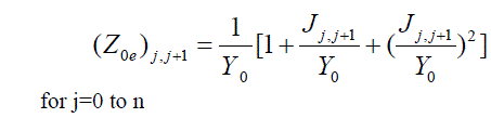
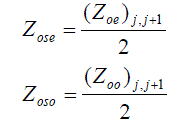
| Using (1) and (2) design equations yield the design parameters, half of which are listed in Table I because of symmetry of the filter, where the even- and odd-mode impedances are calculated for Y=1/Z and Z=50 ohms. |
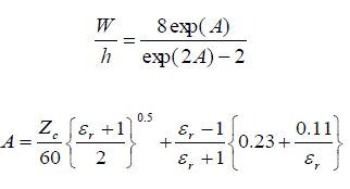
| The next step of the filter design is to find the dimensions of coupled microstrip lines that exhibit the desired even- and odd-mode impedances. Firstly, determine equivalent single microstrip shape ratios (w/d) s. Then it can relate coupled line ratios to single line ratios. For a single microstrip line |
 |
| Use single line equations to find (w/h)se and (w/h)so from Zose and Zoso. With the given r ? =4.2, find that for Zo=50, w/h is approximately 1.95. Therefore, W/h? 2 has been chosen for this case. 2 h W F |
 |
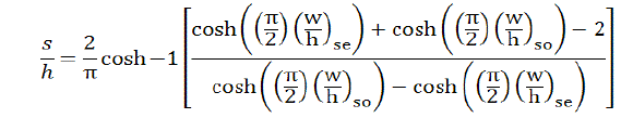
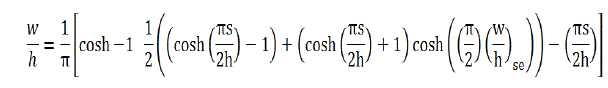
| At that point, it’s able to find (w/h)se and (w/h)so by applying Zose and Zoso (as Zc) to the single line microstrip equations. Now it comes to a point where it reach the w/h and s/h for the desired coupled microstrip line using a family of approximate equations as following |
 |
 |
| The microstrip transmission line by an overall dielectric constant in order to assume TEM propagation. There are a number of formulas, listed for the calculation of eff ? . The most basic formula is given by Pozar as follows: [2] |
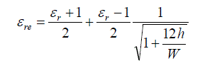 |
| Once the effective dielectric constant of a microstrip is determined, the guided wavelength of the quasi-TEM mode of microstrip is given by |
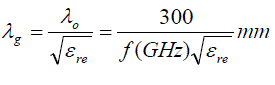 |
Thus the required resonator, 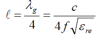 |
| Using the design equations for coupled microstrip lines given (3a) and (3b), the width and spacing for each pair of quarterwavelength coupled sections are found, and listed in Table II |
| The final filter layout with all the determined dimensions is illustrated in Figure 3.2 |
| For section 1 and 4, |
| s/h=0.0288? s=0.046 mm and w/h=1.6106 ? w=2.54mm |
| For section 2 and 3, |
| s/h=0.2728? s=0.431 mm and w/h=2.2368 ? w=3.53mm |
RESULTS AND ANALYSES
|
| All the formulas were coded in MATLAB . The MATLAB response is shown in Figure 3.5. As shown in figure, the MATLAB code gave a center frequency of 2.45 GHz. Spurious modes which do appear due to in-homogeneities of the microstrip [7, 8] are not shown here. |
CONCLUSION
|
| The Edge coupled filter for different center frequency and for different substrates are simulated and we find that for compact design rogerR04003 c substrate is suitable for 2.45GHz frequency .The coupled line filter is a band-pass filter used for narrow bandwidth. Wider bandwidth filters require very tightly coupled lines which are difficult to fabricate. One advantage of this type over the capacitively coupled is the smaller size; it uses quarter wave instead of half wave resonators. |
FUTURE WORK
|
| Physical development and measurement of RF filters design for more accurate design. Use additional software such as ADS simulations to compare the results with MATLAB to accurately determine the final design. |
Tables at a glance
|
 |
|
| Table 1 |
Table 2 |
|
Figures at a glance
|
 |
 |
 |
| Figure 1 |
Figure 2 |
Figure 3 |
 |
 |
 |
| Figure 1 |
Figure 2 |
Figure 3 |
|
References
|
- Matthaei, L. Young, and E. M. T. Jones, Microwave Filters, Impedance-Matching Networks, and Coupling Structures. Boston, MA: Artech House, 1980.
- D. M. Pozar, “Microwave Engineering”, Second Edition, Wiley and Sons, 1998.
- R. Rhea, HF Filter Design and Computer Simulation.Atlanta, GA: Noble Publishing, 1994.
- T. Edwards, Foundations for Microstrip Circuit Design, 2nd edition, England: John Wiley & Sons Ltd.,1981.
- N. Toledo, “Practical Techniques for designing Microstrip tapped hairpin resonator filters on FR4 laminates” 2nd National ECE Conference, Manila,Philippines, November 2001.
- Eagleware Corporation, “ TLine Program,” Genesys version 8.1, Norcross, GA, May 2002.
- T. Yamaguchi, T. Fujii, T. Kawai, and I. Ohta, “Parallel-coupled microstrip filters with periodic oating conductors on coupled-edges for spurious suppression," IEEE MTT-S International Microwave Symposium Digest, 2008.
- K. Singh, “Design and analysis of novel microstrip filter at l-band," in Agilent EESoF 2005 India User Group Meeting, 2005.
|