International Journal of Advanced Research in Electrical, Electronics and Instrumentation Engineering
ISSN ONLINE(2278-8875) PRINT (2320-3765)
ISSN ONLINE(2278-8875) PRINT (2320-3765)
Khadim Moin Siddiqui1, Kuldeep Sahay2 and V.K.Giri3
|
| Related article at Pubmed, Scholar Google |
Visit for more related articles at International Journal of Advanced Research in Electrical, Electronics and Instrumentation Engineering
Induction motor especially three phase induction motor plays vital role in the industry due to their advantages over other electrical motors. Therefore, there is a strong demand for their reliable and safe operation. If any fault and failures occur in the motor it can lead to excessive downtimes and generate great losses in terms of revenue and maintenance. Therefore, an early fault detection is needed for the protection of the motor. In the current scenario, the health monitoring of the induction motor are increasing due to its potential to reduce operating costs, enhance the reliability of operation and improve service to the customers. The health monitoring of induction motor is an emerging technology for online detection of incipient faults. The on-line health monitoring involves taking measurements on a machine while it is in operating conditions in order to detect faults with the aim of reducing both unexpected failure and maintenance costs. In the present paper, a comprehensive survey of induction machine faults, diagnostic methods and future aspects in the health monitoring of induction motor has been discussed.
Keywords |
| Health Monitoring, Induction Motor Faults, Motor Current Signature Analysis, Identification and Diagnosing Techniques |
INTRODUCTION |
| The Squirrel cage induction motors are most widely used electrical machines for industrial, domestic and commercial applications. These motors have advantages such as robustness, simplicity of its construction and highly reliable [1-2]. Since, Induction motors are undoubtedly reliable but we cannot avoid the possibility of failure also. These failure conditions are taking place because of its component failure. If the failure occurs in the machine that failure ought to be diagnose as early as possible. If these failure conditions are not diagnosed on time, the failure component will affect whole motor operation badly and will become more catastrophic. Consequently, large revenue losses and maintenance will be needed [5]. |
| Different faults of induction motors are generally classified as either electrical or mechanical faults. Different types of faults include stator winding faults, rotor bar breakage, misalignment, static and/or dynamic air-gap irregularities and bearing gearbox failures. The most common fault types of these rotating devices have always been related to the machine shaft or rotor. The percentage failure components of induction motor are as shown in fig 1. |
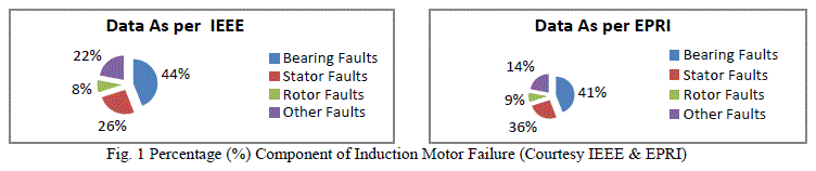 |
| The survey was taken by Institution of Electrical & Electronics Engineers (IEEE) and Electric Power Research Institute (EPRI)[3-4]. According to the IEEE standard 493-1997, the most common faults and their stastical occurrences are shown in fig 1. A 1985 stastical study of the EPRI provides similar results as also shown in fig.1. From the fig 1 it may be clearly observed that the major occurrences of induction motor faults are on rotating shaft as well as stator winding side. |
| In recent years, there is significant progress in the field of the fault analysis and maintenance of induction machines, with the extension of computer techniques, control techniques, and advance intelligence algorithms. Many methods of fault detection are proposed, such as the knowledge based method, the analytical model method and the signal processing method [37,64,90,93]. |
| The classification of induction motor faults is as follows: |
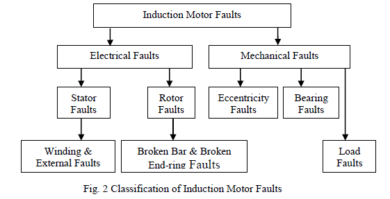 |
| It may be observed from fig 2 that the Induction motor faults basically classified as two faults i.e. electrical and mechanical faults. The stator faults and bearing faults components are failed highly. In rotor related faults, rotor broken bar and broken end ring come in the category. |
| The major faults of induction machines can broadly be classified is as follows [8,12,23,35,43,44]: |
| (i) Stator faults resulting in the opening or shorting of one or more of a stator phase winding; |
| (ii) Abnormal connection of the stator windings; |
| (iii) Broken rotor bar or cracked rotor end rings; |
| (iv) Static and/or dynamic air gap irregularities; |
| (v) Bent shaft; |
| (vi) Shorted rotor field winding; |
| (vii) Bearing & gearbox failures; |
| The health monitoring of the induction machine has always been the challenging task for many researchers. Therefore, they have used a lot of techniques for diagnosing the various existing faults of the induction machine. Those monitoring techniques are[13,34,38,39-43,51,52,,55,57-61,76]: |
| (i) Vibration monitoring |
| (ii) Noise monitoring |
| (iii) Magnetic flux monitoring |
| (iv) Partial discharge monitoring |
| (v) Voltage monitoring |
| (vi) Current monitoring |
| Each method will be discussed in detail in the further sections. In among the techniques, the vibration monitoring technique had extensively used in past successfully for diagnosing the mechanical faults. This technique gives excellent results for mechanical faults such as bearing faults and mechanical imbalance. This method has limited capabilities for diagnosing the induction motor faults. It is able to diagnose mechanical faults for small rating induction machines only not for high rating induction machines [57-61]. |
| The noise monitoring, magnetic flux monitoring, partial discharge monitoring and voltage monitoring methods were used earlier but they required costly sensors. These methods were also having some limited capabilities for fault diagnosis in the induction machines. Therefore, these methods are not used in the current scenario. |
| The current monitoring technique is used these days. Due to the advancement in the digital signal processing techniques (DSP), the fault diagnosis in the induction machine is being easy for the researchers. They used motor current with DSP techniques such as Fast Fourier transform (FFT), Short Term Fourier Transform (STFT) and Wavelet Transform (WT). The FFT technique diagnoses almost all existing faults of the induction machine in the steady state condition but it is found that this method is not able to diagnose faults efficiently where load is varied. It gives excellent results for constant load conditions [34-43]. Therefore, some researchers used STFT method for fault diagnosis purpose. This method is having excellent capability to diagnose faults in the transient conditions. Therefore, early fault detection has been done by this method with constant window size for all frequencies. Since, this method gives constant window for all frequencies. Therefore, it gives good time resolution but with poor frequency resolution [35,65,84-86].Some researchers used WT for induction machine faults diagnosing purpose. This method has excellent features; it is able to diagnose faults in the transient conditions with improved frequency resolution. In this method the size of window is not same for all frequencies. Therefore, frequency resolution is good [33-35,65]. |
| In the present paper, all the induction motor faults, their all possible diagnostic methods, their advantages, disadvantages and future aspects in the health monitoring have been discussed in the further sections. |
INDUCTION MOTOR FAULTS |
| A. Mechanical Faults |
| The mechanical faults occurrence priority is highest in the induction motor. The mechanical faults are classified as bearing fault, eccentricity fault and load fault respectively. |
| 1) Bearing Faults |
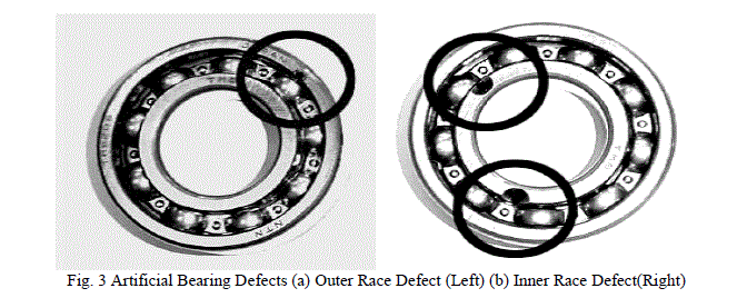
| This fault contains over 40 % of all induction machine failures. The majority of electrical machines use ball or rolling element bearings and these are one of the most common causes of failure. These bearing consist of an inner and outer ring with a set of balls or rolling elements placed in raceways rotating inside these rings as shown in fig 3. In the fig 3 Artificial bearing defects are shown which are outer race defect and inner race defect. Since, the rolling elements of a rolling element bearing ride on races. The large race that goes into a bore is called outer race, and the small race that the shaft rides is called inner race. Faults in the inner raceway, outer raceway or rolling elements will produce unique frequency components in the measured machine vibration and other sensor signals. These bearings fault frequencies are functions of the bearing geometry and the running speed. Bearing faults can also cause rotor eccentricity[7,8]. |
| A continuous stress on the bearing results into the fatigue failures. These failures are at inner or outer races of the bearings. This kind of failures results in rough running of bearings which results in detectable vibrations and increased noise levels, contamination, corrosion, improper lubrication, improper installation and brinelling are the external factors which are also responsible for the bearing fault. Now when the flux disturbance like rotor eccentricities occurs, it results in unbalanced shaft voltages and currents which are also the reason for bearing failures [6]. |
| Temperature is also causing for the bearing failure .So, it is advisable that the temperature should not exceed beyond its predetermined limits at rated load condition. A fault in bearing is imagines as a small hole, a pit or a missing peace of material on the corresponding elements, as shown in fig 3. Now, defecting rolling elements bearings produces mechanical vibrations at the rotational speeds of each component. Consider the hole on the outer raceway. In this case the rolling elements move over the defect. It will stay in contact with the hole which produces an effect on the machine at a given frequency [9]. |
 |
| 2) Eccentricity Faults |
| Air gap eccentricity is common rotor fault of induction machines. Unequal air gap that exist between stator and rotor is known as machine eccentricity. The eccentricity fault produces the problems of vibrations and noise. In the case of healthy machine, the rotor is centre aligned with the stator bore, and the rotor’s centre of rotation is the same as geometric centre of the stator bore. When the rotor is not centre aligned, the unbalanced radial forces (unbalanced magnetic pull) can cause a stator to rotor rub, consequently, damage the stator and rotor [10-12]. |
| The eccentricity is divided into three parts: |
| (i) Static eccentricity |
| (ii) Dynamic eccentricity. |
| (iii) Mixed eccentricity |
| In the case of static eccentricity the position of the minimal radial air gap length is fixed in space. Incorrect positioning of the stator or rotor core at the commissioning stage results into static eccentricity[11]. |
| In the case of dynamic eccentricity, the centre of the rotor is not at the centre of the rotation and the position of minimum air gap rotates with the rotor[11]. The misalignment caused due to the several factors such as bent rotor shaft, bearing wear or misalignment etc. An air gap eccentricity is permissible upto 10%. An inherent level of static eccentricity exists even in newly manufactured machines due to manufacturing and assembly methods [13-14]. |
| Actually, the static and dynamic eccentricities tend to coexist. Ideal centric conditions can never be assumed. Therefore, an inherent grade of eccentricity is implied for any real machine. The combined static and dynamic eccentricity is called mixed eccentricity[14]. |
| 3) Load Faults |
| It is also a one type of mechanical fault. In some applications such as aircrafts, the reliability of gears may be critical in safeguarding human lives. For this reason, the detection of load faults (especially related to gears) has been an important research area in mechanical engineering for some time. Motors are often coupled to mechanical loads and gears. Several faults can occur in this mechanical arrangement. Examples of such faults are coupling misalignments and faulty gear systems that couple a load to the motor [44-45]. |
| B. Electrical Faults |
| The electrical faults are classified as stator and rotor faults. The stator faults and rotor faults mainly occur in the windings. |
| 1) Stator Faults |
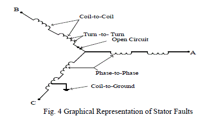
| Less than 40 % of all reported induction machine failures fall into this category. These faults occur mainly due to interturn winding faults caused by insulation breakdown. They are generally known as phase-to-ground or phase-to-phase faults. The stator winding consists of coils of insulated copper wire placed in the stator slots. Stator winding faults are often caused by insulation failure between two adjacent turns in a coil. This is called a turn-to-turn fault or shorted turn as shown in fig 4. The resultant induced currents produce extra heating and cause an imbalance in the magnetic field in the machine. If undetected, the local heating will cause further damage to the stator insulation until catastrophic failure occurs. The unbalanced magnetic field can also result in excessive vibration that can cause premature bearing failures[15-34]. |
| The graphical representation of stator faults is shown in fig 4. The figure shows that all the stator faults occur in the winding. These faults are called as coil-to-coil, turn-to-turn, phase-to-phase, coil-to-ground and open circuit faults. Since, it has been shown in the fig 1from the surveys that the stator fault occurrence has second priority i.e. less than 40%. Therefore, it is important to diagnose these faults in the early stage. |
 |
| 2) Rotor Faults |
| Rotor faults occur about almost 10% of total induction motor faults. These faults are caused by rotor winding. The rotor faults are mainly broken rotor bars because of pulsating load and direct on-line starting. It results into fluctuation of speed, torque pulsation, vibration, overheating, arcing in the rotor and damaged rotor laminations [35-39]. |
| Cage rotors are classified in two parts: cast and fabricated. Cast rotors were only used in small machines. But, now days due to development of casting technology, it can be used for the rotors of machines in the range of 3000kW. While fabricated rotors are generally used in special application machines[40,41]. |
| The reason for rotor bar and end ring breakages are as following [8,15,35,42,43,54,64]. |
| (i) Thermal stresses |
| (ii) Magnetic Stresses |
| (iii) Residual stresses |
| (iv) Dynamic stresses |
| (v) Environmental stresses |
| (v) Environmental stresses |
| Due to the above reasons, rotor bar may be damaged and simultaneously rotor unbalance situation may occur. |
HEALTH MONITORING AND NEED OF HEALTH MONITORING |
| The continuous evaluation of the health of the equipment throughout its service life is called Health monitoring or condition monitoring. It is very essential to detect faults while they are still developing. This is called incipient failure detection [5,33]. This incipient failure detection of motor provides a completely safe environment. The health monitoring of the induction machine provides us continuous assessment of the electrical condition of electrical machines. By using health monitoring, it is possible to provide adequate warning of imminent failure. As a result, we can schedule future preventive maintenance and repair work. This can result minimum downtime and optimum maintenance schedules [5, 46]. |
| The health monitoring and fault diagnosis scheme allows the machine operator to have necessary spare parts before the machine is stripped down, thereby reducing outage times. Therefore, effective health monitoring of electric machines can improve the reliability, safety and productivity of the machine [65]. |
| Health monitoring has great significance in the business environment due to the following reasons [5]. |
| • To reduce cost of maintenance |
| • To predict the equipment failure |
| • To improve equipment and component reliability |
| • To optimize the equipment performance |
| • To improve the accuracy in failure prediction |
| Due to the above motioned advantages of the health monitoring of the induction machines, now, it has been most important to find out the best suitable monitoring technique of induction machine. |
HEALTH MONITORING TECHNIQUES |
| There are a lot of methods which have already been used in the last four decades for health monitoring of the machine but most commonly used techniques are described below: |
| 1) Thermal Monitoring |
| The thermal monitoring of electrical machines can be completed by measuring local temperature of the motor or by the estimation of the parameter. Due to the shorted turns in the stator winding the value of stator current will be very high and hence it produces excessive heat if proper action would not be taken and results into the destruction of the motor. So, some researchers have introduced thermal model of electric motor. Basically this model is classified into two parts: |
| (i) Finite element analysis(FEA) based model |
| (ii) Lumped parameter based model |
| FEA model is more accurate than the second model but it is a highly computational method and also time consuming [49-50]. |
| A lumped parameter based model is equivalent to the thermal network and made from thermal resistances, capacitances and corresponding power losses. In a turn to turn fault, the temperature rises in the region of the fault, but this might be too slow to detect the incipient fault before it progresses into a more severe faults[47-48]. |
| The temperature monitoring technique has been used for bearing and stator fault detection purpose. This method provides a useful indication of machine overheating but offer limited fault diagnosis capability [51]. |
| 2) Magnetic Flux Monitoring |
| Abnormal harmonics which appear in the stator current are functions of a number of variables due to magnetomotive force (MMF) distribution and permeance-wave representation of the air-gap. Hence any distortion in the air-gap flux density due to stator defect sets up an axial flux in the shaft. The axial magnetic leakage flux of an induction motor is readily measured using a circular search coil which is placed on the non-drive (rear) end of the machine, concentric with the shaft. The search coil produces an output voltage which is proportional to the rate of change of the axial leakage flux. This signal contains many of the same frequency components which are present in the stator current. it is particularly useful for estimating the speed as it contains a strong component at the slip frequency[51-52]. |
| 3) Vibration Monitoring |
| Vibration monitoring technique is the oldest health monitoring technique of the induction motor. It is widely used to detect mechanical faults such as bearing failures or mechanical imbalance. A piezo-electric transducer providing a voltage signal proportional to acceleration is often used. This acceleration signal can be integrated to give the velocity or position[13,55]. |
| Almost, all electrical machines generate noise and vibration. Therefore, researchers had been used this vibration for fault diagnosis purpose. They successfully diagnosed several faults from this vibration parameter. Since, very small amplitude of vibration in the machine can produce high noise. Noise and vibration in electric machines are caused by forces which are of magnetic, mechanical and aerodynamic origin [57-60]. The vibrations also can produce due to the inter-turn winding faults, single phasing and supply voltage unbalance [56,57]. |
| The radial forces due to the air gap field are largest sources of vibration and noise in electrical machines. Since, the air gap flux density distribution is product of the resultant mmf wave and total permeance wave. The resultant mmf also contains the effect of possible rotor or stator asymmetries. The permeance wave depends on variation of the air gap as well, the resulting magnetic forces and vibrations are also depends on these asymmetries. Thus, by analyzing the vibration signal of an electric machine, it is possible to detect various types of fault and asymmetries[58-61].therefore, we can say that the vibration monitoring method is most suitable method for detection of the mechanical faults such as bearing fault, rotor eccentricities ,gear faults and unbalanced rotors. Since, many researchers found a very effective parameter i.e. vibration for diagnosis various faults. This method needs expensive accelerometers and associated wiring. Therefore, this limits its use in several applications. Since, this method is expensive and cannot use for large machines fault diagnostics purpose. |
| 4) Partial Discharge Monitoring |
| This method is used for detecting stator insulation faults in higher voltage motors. It consists of detecting the low amplitude, ultrafast pulses(ns) produced by electric discharges in small voids in the insulation. Partial discharge occur even in healthy machines. However an increase in the amount of partial discharge activity can be associated with insulation degradation[76]. |
| 5) Air Gap Torque Monitoring |
| The air gap torque is produced by the flux linkage and the currents of a rotating machine. It is very sensitive to any unbalance created due to defects as well as by the unbalanced voltages. Since, all types of motor faults produce the side bands at special frequencies in the air gap torque. Since, it is not possible to measure air gap torque directly. The difference between the estimated torques from the model gives an indication of the existence of broken bars. From the input terminals, the instantaneous power includes the charging and discharging energy in the windings. Therefore, the instantaneous power can not represent the instantaneous torque. From the output terminals, the rotor shaft and mechanical load of a rotating machine constitute a tensional spring system that has its own natural frequency. The attenuates of the components of air gap torque transmitted through the tensional spring system are different for different harmonic orders of torque components. But by using this method it is not easy to diagnose all faults [77]. |
| 6) Noise Monitoring |
| By measuring and analyzing the acoustic noise spectrum we are able to do noise monitoring. Due to the air gap eccentricity the noise is produced. This noise is used for fault detection in induction motor. However it is not the accurate way to detect the fault by noise monitoring because of the noisy background from the other machines. Ventilation noise is associated with air turbulence, which is produced by periodic disturbances in the air pressure due to rotating parts. The noise is due to the Maxwell’s stresses that act on the iron surfaces. These forces are responsible for producing the noise in the stator structure[78]. |
| 7) Stator Voltage Monitoring |
| This can be safely measured using high frequency differential voltage probe or isolation amplifier. It has been used to calculate the instantaneous power, instantaneous torque and negative sequence impedance[38,61,62]. |
| 8) Stator Current Monitoring |
| The stator current is usually measured using a clip-on hall-effect current probe. It contains frequency components which can be related to a variety of faults such as mechanical and magnetic asymmetries, broken rotor bars and shorted turns in the stator windings. Most of the published research work in recent years has examined the use of the stator current for health monitoring. Particularly using frequency analysis[34-43]. |
SIGNAL PROCESSING TECHNIQUES |
| Signal processing techniques are applied to the measured sensor signals in order to generate failures or parameters (e.g. amplitudes of frequency components associated with faults) which are sensitive to the presence or absence of specific faults. |
| 1) RMS |
| Calculation of simple statistical parameters such as the overall root mean squared (RMS) value of a signal can give useful information. For instance, the RMS value of the vibration velocity is a convenient measure of the overall vibration severity. In the same way, the RMS value of the stator current provides a rough indication of the motor loading[79]. |
| 2) Time-Domain Analysis |
| Time-domain analysis is a powerful tool for a three phase squirrel cage induction motor. In the oscillation of the electric power in time domain becomes mapped in a discrete waveform in an angular domain. Data clustering techniques are used to extract an averaged pattern that serves as the mechanical imbalance indicator. Time domain technique can track the fundamental frequency and slip of the machine and then compute a diagnosis index without any spectrum analysis[80-82]. |
| 3) Frequency Analysis |
| Frequency analysis using the Fast Fourier Transform (FFT) is the most common signal processing method used for online condition monitoring. This is because many mechanical and electrical faults produce signals whose frequencies can be determined from knowledge of motor parameters such as the number of poles. These fault signals appear in a variety of sensor signals including vibration, current and flux. Frequency analysis can thus provide information about a number of faults. Though some faults produce similar fault frequencies and so require other information to differentiate them. It also allows the detection of low level fault signal in the presence of large “noise” signals at other frequencies[34- 43],[65-68].The use of frequency analysis of vibration and current signals has been heavily researched to detect bearing, stator, and rotor and eccentricity faults. |
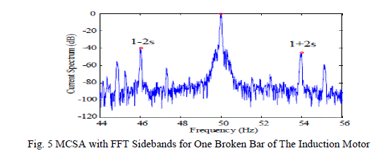
| The fig 5 shows the current spectrum for a motor with one broken bar. This type of analysis is called Motor Current Signature Analysis(MCSA),showing the characteristic (1± 2s) broken bar sidebands around the 50Hz peak[35]. |
| The frequency analysis has also been applied to quantities such as the instantaneous “partial” power and instantaneous torque. Which can be computed from the measured voltage and current signals.[66-71]. |
| This FFT technique is much suitable in the steady state analysis where load is constant. For variable load, fault diagnosis from this method is not suitable. This method is not applied for the fault diagnosis in the transient conditions also. Some researchers also found that the sideband frequencies are overlapped from the fundamental frequency. Therefore, fault cannot diagnose in the no-load condition from this method. The FFT method only gives frequency information it can not give the information at what |
 |
| time which frequency exist. Therefore, some researchers used Short Term Fourier Transform(STFT) and Wavelet Transform(WT) for fault diagnosis purpose[35]. |
| 4) Time-Frequency Analysis Method |
| The conventional FFT method already had been used to detect various induction motor faults but this method is applicable where constant load is required. The FFT method unable to diagnose fault in the transient conditions. This FFT method can do can not reveal at what time what frequency exists. Therefore, to overcome these problems some researchers used shot term Fourier transform (STFT) method for detecting faults in the transient conditions but it shows poor frequency resolution. This method can do 3-dimesional analysis and give time-frequency information simultaneously [83-85]. |
| This resolution problem that was happened with STFT method. Now, this problem has been solved by wavelet transform method. Therefore, in the recent trends wavelet transform is used by several researchers as fault diagnosis method in the induction motor[35,65,84-86]. |
| In the other words we can say, The Fourier transform used for conventional frequency analysis assumes that the frequency spectrum is not changing with respect to time over the sampling period. This assumption is not always valid. Especially with mechanical loads which show consideration variation over time[85,87].The time-frequency analysis techniques overcome this issue by dividing the signal into short time segments over which it is relatively constant, and computing the Fourier transform of each segment. This allows the changes in the frequency content of the signal with time to be observed. Note that the frequency resolution is limited by the size of the segments[86-87]. |
| The wavelet transform is another time-frequency analysis method. The conventional Fourier transform is based on decomposing the measured signal into sinusoids with different frequencies. The wavelet transform decomposes the signal into a set of non-sinusoidal waveforms. It has been generally applied to pulse type waveforms which are not conveniently represented as the sum of sinusoidal components. Various researchers used these methods with stator current sensor signal therefore; these techniques are also called Motor Current Signature Analysis (MCSA) techniques[33-35,65]. |
| 5) Higher Order Statistics |
| Common stastical measures such as the mean or variance can be used to describe the probability density function of time-varying signal. There are also high order stastical measures such as kurtosis, which gives an indication of the proportion of samples which deviate from the mean by a small value compared with those which deviate by a large value. Some of these higher orders statistical measures have the useful property that they are insensitive to Gaussian distributed measurement noise. These have been used to investigate the detection of machine faults[58-59]. |
| It is possible to perform frequency analysis (Fourier transform) of the higher order stastical measures to obtain what is called higher order spectra. These spectra allow the identification of components in a signal which have a fixed phase relationship and hence may originate from the same source[59]. |
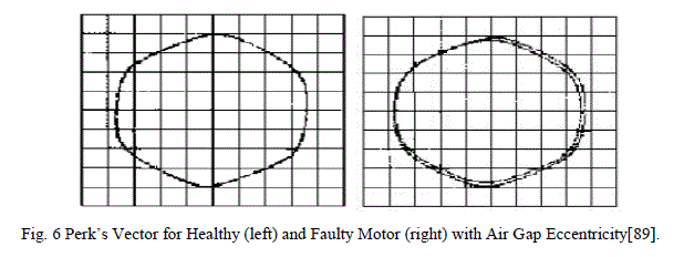
| 6) Stator Current Park’s vector |
| The park’s vector is based on the locus of the instantaneous spatial vector sum of the three phase stator currents. This locus is affected by stator winding faults and air-gap eccentricity. |
| The park’s vector can be analyzed graphically shown in fig 8, or by examining its frequency spectra.[23,89]. From the fig 6, it has been observed that the healthy and faulty curves are different but this method has limited ability to diagnose faults. From this method stator fault can be diagnosed very effectively, but in the steady state operations not in transient operations[23]. |
 |
| 7) Negative Sequence Currents |
| When ideal three phase voltages are applied to a perfectly symmetrical three phase machine, the machine currents are equal in magnitude. A fault such as a shorted turn or eccentricity introduces an imbalance between the phases causing unbalanced phase currents. The imbalance increases with fault severity and can be described mathematically using a negative sequence current component[33,91]. |
| Note: however that imbalances in the supply voltages can also cause imbalances in the phase currents. It is thus necessary to measure the supply voltages so that this can be taken into account[33]. |
FAULT DETECTION METHODS |
| The final and most difficult step in the on-line health monitoring process is to examine the features and fault parameters extracted in the previous section and to decide if a fault exists, and if so, what type of fault. Presently this is often done based on the knowledge and experience of an expert user. However, there has been considerable research into means for automating this process using classification techniques such as artificial intelligence and pattern recognition. |
| The key difficulty with this step is the sensitivity of the measured fault parameters to machine specific details such as size, power, construction type and loading. Thus for a reliable fault detection /classification algorithm to be developed, an extensive set of “healthy” and “faulty” reference data is generally required. The final accuracy of the fault detection algorithm is clearly limited by the size, breadth, and quality of the reference data which was used to develop it. |
| 1) Model Based Approaches |
| The effect of particular faults on parameters such as the machine output current can be predicted using analytical [91] or finite element modelling approaches [92]. These models can allow accurate fault diagnostics for a given machine. If detailed electromagnetic machine design information is available. Note that it may be difficult to use the results from one motor to set general fault thresholds [53,92-93]. |
| 2) Trending |
| This involves observing a fault parameter over a period of time so that it will be able to detect sudden changes which would be associated with the presence of faults. Still, there is difficulty of the determining of much of a change in the parameter corresponds to a fault detection [92]. |
| 3) Fault Thresholds |
| The simplest fault detection algorithm is to use a threshold for a given parameter. For instance, there are tables which show the acceptable levels of mechanical vibration amplitude depending on the size of the machine [57]. Another example is the “rule of thumb” for the broken bar sidebands in the current spectrum. It has been reported that if these side bands are less than -54dB with respect to the main peak then the motor is healthy. If they are greater than -54dB then the motor is faulty, else it is marginal [65]. |
| 4) Multi-Dimensional Space Techniques |
| Multiple fault parameters can be taken into account by representing each fault parameter as one dimension of a multiple-dimensional space. A given set of parameters corresponds to a point in this space. Points for healthy operation are located in different regions in this space from points for faulty operation. |
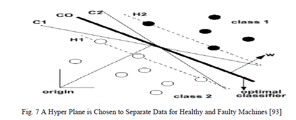 |
| The support vector classification approach [69,94] tries to find a linear combination of parameters (geometrically represented by a hyper plane) that will separate the healthy data from that faulty data as shown in fig 7. Another approach is to try to define geometric regions in the space which correspond to healthy operation and to faulty operation[69]. |
| 5) Neural Networks |
| Artificial neural networks are modelled on the neural connections in the human brain. Each artificial neuron accepts several inputs, applies preset weights to each input and generates a non-linear output based on the result. The neurons are connected in layers between the inputs and outputs[94-95]. |
| The training of the neural network is performed by feeding in selected sets of parameters corresponding to known healthy and faulty machines and adjusting the input weights of the neurons to give the required output in each case[63]. |
| 6) Fuzzy Logic |
| This involves making decisions based on classifying signals into a series of bands(fuzzy values) rather than simply as healthy or faulty based on a single threshold. For instance, based on the broken bar side band amplitude, a motor could be classified as healthy, marginal or faulty. Fuzzy logic allows combining fuzzy information from different signals together to make a more accurate judgment regarding the health of the motor[95-96]. |
| 7) Expert Systems |
| Expert systems seek to represent the knowledge of a human expert by defining a series of rules from which conclusions can be drawn. An example of a rule could be: if the broken bar side bands are greater than -45dB and the Park’s current vector is a circular then it is likely that a broken bar fault is present[92,97]. |
PROCESS OF ONLINE HEALTH MONITORING |
| The process of online health monitoring can be understood by the fig 8. The block diagram comprises of five blocks. The motor fault blocks shows the faults occur in the induction motor, sensor signal block shows to choose a suitable signal for fault diagnoses purpose. This sensor signal plays vital role for the diagnosing of faults. It has been observed from the previous researches, many researchers used several sensor signals such as vibration, noise, flux, torque but all the mentioned signals required costly sensors. Therefore, researchers used motor current for fault diagnosis purpose. This motor current differentiated healthy and faulty motor waveforms effectively [34-37,65]. Therefore, from last 2 decades by the advent of several signal processing techniques, researchers used the motor current for fault diagnosis purpose. |
| The signal processing block gives the details of methods used for the fault diagnosis purpose. It has already been discussed that the wavelet Transform(WT) technique is the most suitable technique for diagnosing the induction motor faults[35,65,84-88]. It gives time-frequency information simultaneously with improved resolution. By the invention of WT method we can do incipient fault detection, in the other words can say to diagnose faults in the early stage i.e. in the transient conditions. |
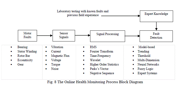 |
| Therefore, fault will not be more catastrophic and will not disturb the whole operation of the motor. Important and interesting thing to be discuss here, the fault was diagnosed earlier by the expert systems also. They had knowledge with their experience and can guess that a particular fault is going to occur. It was not extremely correct method but some researches have shown that they have diagnosed the fault efficiently [92]. This kind of detection process is called OFF-line fault detection process. |
FUTURE AREAS FOR RESEARCH |
| 1) Use of Multiple Sensor Types |
| The majority of present research has been carried out by a single sensor signal(e.g. motor current) with a particular signal processing technique(e.g. FFT) to detect a given fault. In the future work we can use multiple sensor signals with processing techniques. As a result, accuracy of fault detection will be improved. |
| 2) Detection and Diagnosis of Multiple Faults |
| There has been little work carried out on the identification of multiple faults in machines. This may be complicated by the inter-dependencies of the fault signals if there is more than one fault. The use of multiple sensors types and processing techniques may also be helpful for this work. |
| 3) Detection Based on The Varying Load Conditions |
| Many researchers have usually worked in the detection of faults only for under full load conditions. Though, in practice it has been seen that for actual load when machine is tested may not be controllable. Partial load operation can significantly changes the fault signals. For instance, it has been shown that the broken bar sidebands of the current spectrum are sensitive to the machine loading [35]. |
| 4) Portability of Methods |
| It is difficult to generalise the results from laboratory testing on what are normally low power machines to the much high power machines found in the field. For a fault diagnosis system to be practical, it must be applicable to machines with widely different ratings and different construction with little incremental effort. |
| 5) Fault Detection in Inverter-Driven Motors |
| It has been observed that from the previous research works that was already carried out by other researchers. They have detected those induction machines faults were operated directly from the mains. In the current scenario, the Inverter driven motors are used in the industry despite of noise, at increasing power levels. The detection of faults in inverterdriven machines is challenging due to noise created by the high switching frequency. On the other hand, the presence of a microcontroller and sensors in an inverter mean that health monitoring algorithms can be implemented with a little bit high cost. |
| 6) Remote Machine Monitoring |
| The remote monitoring system can also be useful in the future work. It is useful to have continuous remote monitoring of induction machines in unmanned/hazardous locations (such as remote mining sites or petroleum processing plants) and in critical applications where the highest reliability is required. |
CONCLUSION |
| In the present paper, a comprehensive review of induction motor faults and their detection techniques have been carried out. The accurate health monitoring technique of the induction motor can improve the reliability and reduce the maintenance costs. It has been observed from previous year’s research papers that the fault diagnosis in the induction motor is still a challenging task for researchers and academicians. Many researchers found that the stator current is much suitable signal for the fault diagnosis purpose. It has been observed from the various research papers that the majority of work was oriented towards constant speed induction motor. There are various methods which are used to diagnose faults for the constant speed induction motor like fuzzy logic, neural networks and genetic algorithm etc. |
| By the invention of several digital signal processing techniques, it will be easier to diagnose faults of the variable induction machines also. A lot of work has to be carried out for variable speed induction motor. So, for small rating induction motor faults has been analysed but for the large rating motors that the fault diagnosis and analysis will be challenging task. From the comprehensive survey, it has been found that the Fast Fourier Transform (FFT) method used for steady state analysis and the Wavelet Transform (WT) used for transient analysis with Digital Signal Processing (DSP) methods gives outstanding results. But, it has been found that the FFT method is not able to diagnose fault in the no-load conditions unlike WT. These methods are called Motor Current Signature Analysis (MCSA) methods with motor current. |
| Therefore, it has been observed that the MCSA technique can be used in the fault diagnosis of induction machine in the transient conditions with wavelet transform. But, with the wavelet transform only some limited work has been carried out. It has been observed that the wavelet transform diagnoses many faults successfully in the transient conditions. But, for inverter fed induction machines some introductory level work has been done by the researchers. Now, it will be interesting to see, in the future whether the wavelet transform tool will be able to diagnose faults for the inverter fed machines also or not. Therefore, the time-frequency transient fault detection capability of this wavelet transform tool with improved resolution could be the important tool for the early fault detection purpose in the inverter fed machines too. In fact, in the industries inverter fed machines are used inspite of noise. Therefore, now researchers will have to face the challenges to diagnose induction motor faults in these conditions also. |
| ACKNOWLEDGMENT |
| The first author “Khadim Moin Siddiqui” is a teaching cum research scholar in the Department of Electrical Engineering, Institute of Engineering & Technology, Lucknow through Technical Education Quality Improvement Program (TEQIP). They are financially assisting me to carry out my research work. Therefore, special thanks to the TEQIP committee for their support and dedication. Author is also thankful to Faculty and Staff of IET, Lucknow and the M.M.M. University of Technology for their support. |
References |
|