ISSN ONLINE(2278-8875) PRINT (2320-3765)
ISSN ONLINE(2278-8875) PRINT (2320-3765)
| Anna Maria Jose, Priyanka Rajendran and Dr.GnanaSheela K Department of ECE, Toc H Institute of Science and Technology, Kerala, India |
| Related article at Pubmed, Scholar Google |
Visit for more related articles at International Journal of Advanced Research in Electrical, Electronics and Instrumentation Engineering
This paper goes through an overview of an emerging display technology; Heliodisplay. It is an air-based display, using principally air that is already present in the operating environment. The system uses a projection unit focused onto multiple layers of air and dry micron-size atomized particles in mid-air, resulting in a two-dimensional display that appears to float. The system comprises a self-generating means for creating this dynamic, non-solid particle cloud. Particle cloud is created by ejecting atomized condensate present in the surrounding air, in a controlled fashion to air. A projection system consisting of an image generating means and projection optics, projects an image onto the particle cloud. As dark areas of the image may appear invisible, the image may be more realistic than on a projection screen, although it is still not volumetric. Any physical intrusion, occurring spatially within the image region, is captured by a detection system and the intrusion information is used to enable real-time user interaction in updating the image. A PC sees the Heliodisplay as a pointing device, like a mouse. Finger, pen, or another object can be used as cursor control and navigate or interact with simple content. The interactive version ("i") of the heliodisplay contains an embedded processor that controls these functions internally for single touch, or multiple touches.
Keywords |
| Interactive display, particle cloud, base unit, projection source unit |
INTRODUCTION |
| Over the years, display technology has been growing, from simple CRT to plasma screen. When computers first allowed people to manipulate the image on the screen, people were fascinated. Take away the screen and leave the image suspended in air, and people will feel as if they have been transported years into the future. Now display technology has reached a stage where images can be displayed in thin air without the aid of a screen. The Heliodisplay is a free-space display developed by IO2 Technology. It was invented by Chad Dyner. IO2 Technology holds the patent for heliodisplay technology. In the Heliodisplay, a projector is focused onto a layer of mist in mid-air, resulting in a two-dimensional display that appears to float[1]. As dark areas of the image may appear invisible, the image may be more realistic than on a projection screen, although it is still not volumetric. The Heliodisplay transforms water into a unique screen of fine vapour, suspended in mid-air to create a nearly invisible screen into which any image can be projected. Looking directly at the display, one would also be looking into the projector's light source. |
| Projection onto non-solid screens was first suggested in 1899 by Just where an image was projected onto a simple water screen known as fog screen projections[2]. Since then,general advancements to image quality have been described depending solely on improving the laminar quality of the screen directly correlating to image quality. These methodologies limit the crispness, clarity, and spatial image stability solely based on the dynamic properties of the screen which intrinsically produce a relativelyunstable image in space. Image fidelity was further compromised and image aberrations were amplified by the easily discernible screen detracting from the intended objective of free-space imaging. One of the main disadvantages found in fog screen was the reliance on a supply of screen generating material. These devices depended on either a refillable storage tank for the screen generating material, or the device had to be positioned in or around a large body of water such as a lake in order to operate. This limited the operating time of the device in a closed environment such as in a room. It required refilling, or a plumbing connection for constant operation. The result severely limited the ease of operation, portability, and placement of the device. Furthermore, some fog screen projection systems changed the operating environment by over-saturating the surrounding ambient air with particulates, such as humidity or other ejected gases. The constant stream of ejected material created a dangerous environment, capable of short-circuiting electronics equipment as well as producing a potential health hazard of mold build-up in a closed space, such as in a room[2]. While a relatively laminar screen can be achieved using existing methodologies, generating a spatially stable and clear image is limited by depending solely on improvements to the screen. This is obtained in heliodisplay. |
SYSTEM OVERVIEW |
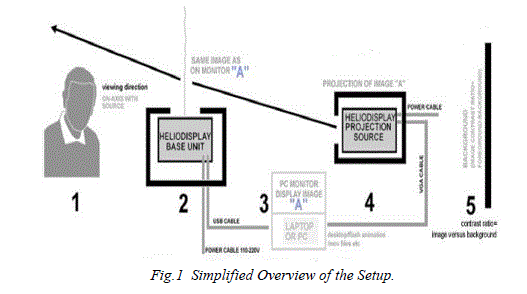
| Heliodisplay has two parts, a base unit and a projection unit. Fig.1 shows the simplified overview of the setup. The base unit produces the water vapour screen necessary to display the image. The projection source unit projects images onto the mid-air. The image can be viewed from behind the base unit. |
 |
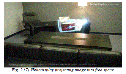
| Chad Dyner explains, “Heliodisplay creates a dynamic, non-solid particle cloud by ejecting atomized condensate present in the surrounding air, in a controlled fashion, into an invisible particle cloud.” That is a heliodisplay runs on particles already present in the air. Particles in the air are converted into nearly atom-sized particles, and are re-emitted upward through a dozen metal plates. These particles, about the size of printer ink droplets, are held together by surface tension and form a cloud that can act as a screen. By changing the molecular properties of this cloud, the qualities of the image, like brightness and sharpness, can also be changed. The cloud is invisible and walk through. Currently, a disadvantage is that the screen is essentially air, so it can become distorted with too much air movement in the room. Fig.2 shows heliodisplay projecting image into free space. No fog or any other chemical additives is required. Heliodisplay does not affect the environment as it works using the existing air that is already in the room to create the image. It transforms air into a unique screen of fine cloud, suspended in mid air to create nearly invisible screen into which any image can be projected. This vapour curtain (screen) is sandwiched between layers of clean air to create an acceptable screen. This vapour screen is a particle cloud created by passing the surrounding air through a heat pump which in turn cools the air to a level below its dew point. These particle clouds consist of individual micro droplets, held together by surface tension. Internal or external tanks can be installed to provide a continuous supply of water for the unit. The capacity of these tanks depends upon the nature of application and the duration of operation of the device. |
 |
SYSTEM DESCRIPTION |
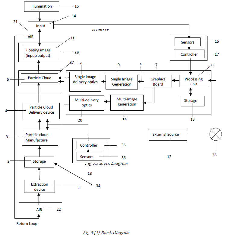
| Fig. 3 shows the block diagram of the system. It shows the basic elements of heliodisplay. Main working of the device can be seen as three parts; the screen preparation section, the input section and the interactive section. |
| A. Screen Preparation |
| The base unit of heliodisplay extracts moisture from the surrounding air (22) through a heat pump extraction device (1), utilizing solid state components such as thermoelectric (TEC) modules, compressor-based dehumidification systems or other means of creating a thermal differential, resulting in condensation build-up for subsequent collection. This air coming from the heat pump extraction device is passed through a cold surface, cooling it below its dew point, so that it becomes condensate. This condensate is stored in a storage vessel (2). This storage vessel can also have an external connection (34), for additional refilling with water for operation without the extraction device[1]. A level sensor is controls the level of condensate in the vessel, preventing it from overflowing. |
| The condensate which is stored in the storage vessel is sent to a particle cloud manufacturing system (3). This system alters the condensate by mechanical, acoustical, electrical or chemical means, or a combination of one or more means, into microscopic particle cloud material (5). A piezoelectric disk, vibrating ultrasonically, atomises the condensate, generating a fine cloud of mist. It is then passed to Particle cloud delivery device (4). It mixes the mist with air, and the air-mist mixture is ejected to surrounding air (21), locally re-humidifying it. The velocity of ejection is determined by the height required for the screen. This creates a nearly invisible particle cloud screen (5), contained within a controlled microenvironment (37). |
| Environment Management Control (EMC) system (18) comprising of controllers (35) and sensors (36) adjust screen density (number of particulates per defined volume), velocity and other parameters of particle cloud. EMC continuously modifies the microenvironment and particle cloud ejection velocity to compensate for any change in particle cloud density. The particle cloud density determines the visibility of the cloud. External ambient conditions such as temperature, humidity, and ambient lighting are read by sensors (36), and sent to controller (35), which interpret the data and instruct particle cloud manufacturing system (3) to adjust the cloud parameters[1]. A photoemitter placed on one side of the particle cloud and photo-detector on the opposite side, can be employed to calculate the visibility of the cloud by monitoring the amount of light passing from emitter to detector, thereby maximizing the invisibility of the cloud. The loss in signal strength due to the light reflected off particle cloud and not received by detector corresponds to the cloud density and therefore visibility of the cloud. This signal can be sent to controller to regulate density and velocity modifying visibility of cloud. This ensures an effective screen for imaging. |
| B. Input from External Source |
| Signals originating from an external source (12), a VCR, DVD, video game, computer or other video source, are passed through an optional scan converter (38). Optical scan converter converts the video signal to light signals for processing. These signals are sent to processing unit (6), to be decoded. Stored video data (13), (for example, data contained on a hard disk, flash memory, optical, or any other alternate storage means), is the source of content. The processing unit (6), receives these signals, interprets them and sends instructions to graphics board (7). Graphics board generates video signal (8). This signal is sent to an image generating means. It can be single image generation or (9) multi-image generation (10). It produces a still or video image. The image generators have a means of displaying still or video data for projection. It can Liquid Crystal Display, (LCD), Digital Light Processing unit (DLP), Organic Light Emitting Diodes (OLED’s). Sometimes the image generators may even have a laser based means of directing or modulating light from an illumination source. This is used to generate a still or video image. |
| Single image delivery optics (10), comprising telemetric projection optics includes adaptive anamorphic optics for focusing onto non-linear screens, such as curved surface screens. In the multisource embodiment, a single projection source (9) includes a multi-delivery optical path (20), comprising a series of lenses, prisms, beam splitters, mirrors, as well as other optical elements required to split the generated image[1]. From here, the projection beam is redirected to the particle cloud. An alternate method of displaying available is the multi-image generation. Here, multiple images are generated on either a single image generator, such as one projection unit or multi-image generators (19). Multi-image generators have more than one projection units. The images are then directed, using a single optical delivery path (10), or multiple delivery paths using multidelivery optics (20). Optical or software based means or a combination of both are used for correct focusing and on axis projection of the image. The directed projection illuminates particle cloud (5) and the image appears to be floating in air. The free-space image (11) is floating in protective microenvironment (37) within the surrounding air. Microenvironment (37) increases boundary layer performance between the particle cloud and the surrounding air. This is done by creating a protective air current with similar ejection velocity as that of particle cloud. This microenvironment (37), and particle cloud (5) characteristics are continuously optimized to compensate for changing environmental conditions, in order to minimize cloud visibility. |
 |
| C. Interactive Input |
| For the interactive input section, an input detectable space (39) coexists spatially with the image (11). This allows the image to serve as input/output device. Any physical intrusion within the input detectable space of particle cloud, such as is recognized as an input instruction (14). The intrusion can be a user’s finger, a pen or any other foreign object. The input is registered when an illumination source (16), comprised of a specific wavelength, such as infrared (IR) source, is directed towards the detectable space highlighting the intrusion. The illumination reflects light off a physical object within a defined detectable region. This is done by utilizing a laser line stripe, IR LED’s, or conventional lamp. This can also include the same illumination source from the image projection, illuminating the detectable space. The area in which the image is being composed is monitored for any foreign physical intrusion such as a finger, hand, pen or other physical object such as a surgical knife. The operating detection system wavelength does not interfere with the image and remains unnoticed by the user. So, a narrow bandwidth illumination source, beyond the visible spectrum, such as infrared (IR) rays are preferred. |
| The reflected light, which is scattered off the user’s finger or other intrusion, is captured by optical sensor (15). It includes a charge coupled device (CCD) or a complementary metal-oxide silicon (CMOS) sensor or a similar type of detector or sensor capable of capturing image data. The optical sensor is capable of filtering unwanted noise. This is done by operating at a limited sensitivity response i.e., with a wavelength similar to or equal to that of the illumination source. Specific band-width sensors or band pass filters or a combination of both can be used for this. Light beyond the bandwidth of the sensor is ignored, diminishing background interference. Thus only the intended input is recognised. The coordinate in space where the intrusion is lit by the illumination source corresponds to an analogous two or threedimensional location within a computer environment. Thus the intrusion input acts as a mouse cursor. The highlighted coordinates, captured by the sensor are sent to controller (17). The controller read and interprets the highlighted input data using blob recognition or gesture recognition software at processing unit. Tracking software instructs the operating system or the application running in the processing unit to update the image. |
IMAGE FORMATION |
| The particle cloud composition consists of a vast number of individual condensate spheres held together by surface tension. These spheres have mean diameter in the range of one to ten micron. They are too small to be visible individually by a viewer, yet large enough to provide an illuminated cloud for imaging. The light from source is focused onto these spheres with controlled illumination. This allows the individual spheres to act as lenses, transmitting and focusing light. The highest intensity is when the image is viewed on-axis, i.e., the observer positioned directly in front of both screen and projection source can see the image at its brightest and clearest. Viewing an image clearly from all directions is also made possible. This is done by projecting images from multiple sources. When image is projected from multiple sources, the intersecting light rays maximize the illumination at the intended image location. |
| Fig. 4 shows the optics of an individual cloud particulate. An individual particle, which is sphere shaped acts as a ball lens. |
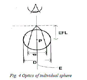 |
| D is the diameter of the near perfect sphere of the particulate formed naturally by surface tension. The incoming light follows along path E, and is diffracted as it enters sphere, with a resolution d. The light ray is focused at a distance EFL (effective focal length. The focused point is on-axis with E. Therefore the maximum intensity is observed when the image is viewed on axis. This process is repeated on adjacent particulates throughout the depth of the cloud and continues on-axis until it finally reaches the viewer’s position. The on-axis illumination intensity is determined by source intensity and the depth of the cloud. The maximum intensity and clarity is in front, on-axis at zero-degrees and lowest intensity and clarity is when viewed from behind at 180 degrees. That is, i.e., the floating image can be viewed clearly from the front of the screen and is invisible, from behind. This serves as a privacy one-way screen. So, the cloud, from the rear side, thereby provides an empty surface to project an alternate image. The same image as on the front side or a discrete image can be projected to the rear side of the screen. |
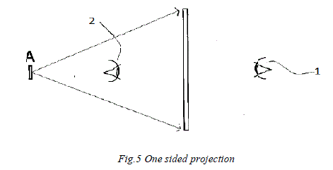
| Fig. 5 shows the projection of image to one side of the screen. The image A is projected onto the particle cloud[1]. A viewer at position 1 can see the image clearly, while for the one viewing from position 2, the image is invisible. |
 |
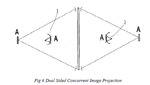
| As said above, the rear side of the screen can be used as a second screen to project same or discrete images. Fig. 6 shows an image ‘A’ being projected onto both sides of the screen separately. Here, viewers located at both position 1 and 2 can view the image. |
 |
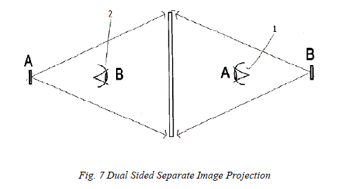
| On the other hand fig. 7 shows a dual viewing embodiment, i.e. two discrete images are projected to both sides of the screen. Observer located at position 1 can see image ‘A’ clearly and image ‘B’ is invisible to him. Similarly, observer at position 2 can see the image ‘B’ and image ‘A’ is invisible to him. |
 |
RECENT DEVELOPMENTS |
| Ever since the invention of heliodisplay, a number of heliodisplay models were developed by IO2 Technology. Each model is an updated version of its predecessor, rectifying its limitations. “i” is the interactive version of the model. |
| A. Model M1: |
| The initial model M1units produced by IO2 were advanced prototypes and proof-of concept. These are the first heliodisplay developed by the IO2 technologies[4]. They have less fidelity. These first generation heliodisplays support only a 22” image. |
| B. Model M2: |
| The second-generation M2Heliodisplay supports a 30” image with 16.7 million colours and a 2000:1 contrast ratio. Its images were unique and offered many advantages over existing displays. The M2 is about the size of a tower desktop computer case turned on its side. The interactive M2iversion included virtual touch screen capability. It allows a finger placed on the floating image to act as a computer pointing device. The user was able to interact with floating images or video, and manipulate them as you could do with a mouse, including clicking and dragging. Its power consumption was 350W. |
| C. Model M3 and M30: |
| The third-generation M3version has the same basic specifications as the M2but is much quieter, with improved brightness and clarity and more stable operation with an improved triflow system. Apart from displaying at a standard ratio of 4:3 in addition it also displays 16:9 widescreen ratios. These improvements allow the display to begin to offer advantages in markets such as teleconferencing, board room displays, and as an access point for gathering information in hotel and corporate lobbies. The heliodisplay M3 is available directly from IO2. There is also an interactive version called the M3i.M3i serves as a computer input device for cursor control in a desktop environment. The M30is the updated version of the M3, which fits into the current model numbering system, 30 designating the diagonal screen size. |
| D. Model M50 and M100 |
| In late 2007, IO2 Technology introduced two larger Heliodisplays, the M50 and 100. The M50 has a 50” diagonal image, equivalent to displaying a lifesize head-and-shoulders person. The M100 has a 100” diagonal image, equivalent to displaying a large full-body person (about 2 meters tall). |
| E. Model L90 |
| L90 is another model developed of heliodisplay by the IO2 Technologies. This is also an updated version of previous models. It has an interactive version also, called L90i. L90 is backward compatible. |
| F. P-Series |
| P-series Heliodisplay Projection systems are designed with simpler operation functionality and advanced controls for integrating and use. P-series incorporate an optical synchronisation between components that they are in direct communication link so only one button or trigger is required to operate as they all turn on and shut down in sync. Communication ports allow for the helio projection and helio base to be controlled remotely in an installation via a remote controller or PC. Built in gesture control allows even simpler operation, such as hand waving to turn on the unit without actually touching the device. To project the images and videos, air should be touched[4]. The PRX2 projection unit includes proprietary baffling to reduce the viewing of the light source and beam-steering optics shorten the throw distance by 10”(25cm) while simultaneously allowing for easy control of the projection angle without even moving the projection. In addition, and only available in the in the P92”, the base system can operate in any orientation from 0-180 degrees. It also has USB playback from projection unit. |
| The new display technology has many advantages and since it’s an emerging technology, it has its limitations. The main advantages are: |
| • No screen to project images. |
| • No special glasses are required to see the display. |
| • Device is light weight and can be converted into a furniture. |
| • Since nothing is added to air, the air quality is not affected. |
| • Projected images and video are 2D, but appear 3D since there is no physical depth reference |
| • Heliodisplay does not create fog, so no electronic devices in the room are affected. |
| • Heliodisplay can be used in any climate since it works on 95-115ºC or 220-240V ac |
| • Heliodisplay, imagery can be seen up to 75 degrees off aspect for a total viewing area of over 150 degrees |
| • Translucency is controlled by the heliodisplay And the limitations include |
| • Heliodisplay is very expensive. |
| • Viewing a Heliodisplay image in direct sunlight is almost impossible. |
| • Screen is essentially air, so it can become distorted with too much air movement in the room. |
| Proposed applications for the real-world Heliodisplay include: |
| • Advertising and Promotion, e.g.: trade shows; in-store displays; museum, movie and casino displays; theme parks. |
| • Collaborative Decision Making, e.g.: board meetings and presentations; air-traffic control; |
| • Military command and control; architectural and engineering design; teleconferencing. |
| • Simulation & Training, e.g.: virtual targets; pre-operative planning; virtual surgery. |
| • Consumer applications, e.g.: video games; home theatre. |
| • Heads-up displays in new fields, e.g.: a patient's vital signs could hover above the chest during open heart surgery. |
| • Build one into a door jamb and have a walk through image or virtual privacy screen. |
| • An in-store end cap advertising display and demonstration through which the customer can reach and grab shown product. |
CONCLUSION |
| The heliodisplay is a relatively new technology and is still being developed. Heliodisplay works as a kind of floating display and touch screen, making it possible to manipulate images projected in air with our fingers. Though it has some flaws the attention that it brings is enormous. Its various applications such as in advertising, a board room etc suggests that its future scope is very large. Several other thin air-displays are available but heliodisplay out classes them as it adds nothing to air and keeps the atmosphere clean. As a result it has more market value. Though it is currently expensive and unaffordable heliodisplay technology has a great potential. More researches on the topic and further advancements of the product may make it more popular, bringing the cost down. It is the future generation display where we can see images projected into mid-air without the help of a solid screen. It could be used for museum or trade-show displays or for advertisements, and would be ideal for collaborative work. |
| As advocated by IO2 technologies, heliodisplay is just the beginning of the future generation displays to come. Heliodisplay therefore can be considered as the foundation blocks for the future generation display technology. A future generation display might incorporate the best of heliodisplay with some additional features like open-air display with 3D capability, higher resolution and more accurate interactive capabilities. |
References |
|