International Journal of Advanced Research in Electrical, Electronics and Instrumentation Engineering
ISSN ONLINE(2278-8875) PRINT (2320-3765)
ISSN ONLINE(2278-8875) PRINT (2320-3765)
| Anjali.R.Prakash PG Student [PEPS], Dept. of EEE, Amal Jyothi college of Engineering, Kottayam, Kerala, India |
| Related article at Pubmed, Scholar Google |
Visit for more related articles at International Journal of Advanced Research in Electrical, Electronics and Instrumentation Engineering
The utilization of photovoltaic energy becomes an key source of electrical energy with the advancement in power electronic technology. The dc-dc converters is connected to PV system, for connecting the source to the grid or AC load through an inverter. MPPT (Maximum Power Point Tracking) increases the power production of the PV system. The advantages of high step up converters integration with voltage multiplier includes improving voltage gain without using extreme duty ratio, reduction of voltage stress, current ripple and conduction losses are desirable for renewable energy applications. A multilevel hybrid cascaded inverter is connected high step up converter for connecting to the ac load.
Keywords |
| High step up converter, voltage multiplier, renewable energy, photovoltaic system, high gain. |
INTRODUCTION |
| With the development in power electronics technologies the renewable energy sources utilization become an increasing trend for electrical energy. The photovoltaic system is a feasible energy source in research and development work in power system and power electronics. High performance dc to dc converter can be obtained with MPPT technique and islanding detection for photovoltaic system are now considered for the interface to the grid or ac utilities [4]. The DC/AC inverters control the output voltage of DC/DC converter and generate a fundamental real power required for the loads. |
| A voltage multiplier is a device which converts the low voltage input to a higher voltage by means of capacitors and diodes combined circuit. The voltage multiplier helps in reducing the turns ratio of transformer for better performance. |
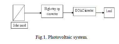 |
| The high step-up converter helps in improving the voltage gain, reduction of voltage stress and current ripple with optimized circuit performance. The integration of voltage multiplier reduces the input current ripple, hence the increases the life of PV arrays of the photovoltaic system. The output from PV, 30-40V is stepped to 300-400V by using dc-dc converters. The main factor depends on the selection of the PV array or cells in the photovoltaic system are the cost and efficiency. A novel cascaded hybrid inverter is connected to the output of the high boost converter for connecting ac loads in a photovoltaic system are discussed in this paper as shown in fig 1. |
MODELLING OF PHOTOVOLTAIC CELL |
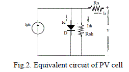
| The solar radiations from the sun are converted to electric energy by the photovoltaic effect. The photons from the sun having band gap energy higher than the semiconductor material used, will produce electron-hole recombination, which depends on incident radiation. Electron-hole recombination result in the flow of photocurrent[5].The PV system depends on the cell temperature and solar insolation have non-linear characteristics for P-V and I-V curves. The equivalent circuit of the PV system is shown in fig 2. The PV modules can be connected in series and parallel to obtain required value of voltage and current. |
 |
 |
MODELLING OF MPPT ALGORITHM |
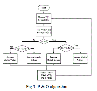
| Maximum Power Point Tracking (MPPT) technique is to extract maximum power from photovoltaic systems. Here the PV system uses P & O algorithm because of simplicity, less time and parameters requirement. The algorithm starts with setting the reference voltage and power of the module. The flowchart for P & O algorithm is discussed in the fig 3. |
 |
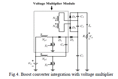
BOOST CONVERTER INTEGRATION WITH VOLTAGE MULTIPLIER |
| The pulses are obtained from the MPPT algorithm are given to the switches as switching pulses. The output from the PV panel are in the range of 30-35V. The boost converter on combining with voltage multiplier to get high gain output at the load. This topology reduces the conduction losses, improves the efficiency and gain of the converter for connecting it to an inverter for connecting ac loads[1]. The switching frequency is given for 40kHz and provided with a load of 200Ω. The turns ratio are set to be 1:1. The secondary’s of the two coupled inductors are connected in series for high gain output. |
| The advantages of integration of voltage multiplier with high step up converter for increasing voltage conversion ratio and gain. The circuit diagram is shown in figure 4. |
 |
 |
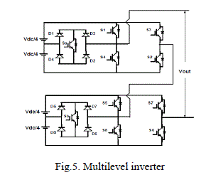
HYBRID MULTILEVEL INVERTER |
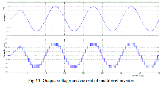
| A multilevel inverter uses sinusoidal pulse width modulation technique with phase disposition principle[2]. Here we use single phase 9-level hybridised cascaded multilevel inverter for connecting it to the output of high step up converter. The MLI is shown in figure 5. The modulation index are controlled for getting the desired number of levels of the inverter’s output voltage.The output voltage when the switches ON and OFF. Proper switching of the inverter can produce nine output-voltage levels: Vs, 2Vs,3Vs, 4Vs, 0, −Vs, −2Vs, −3Vs, −4Vs. |
 |
SIMULATION RESULTS |
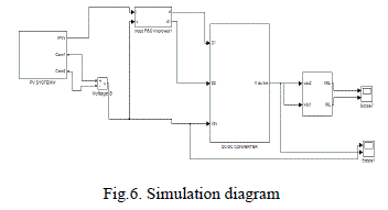
| The simulation is done on MATLAB simulink. The simulation diagram consists of PV modeling, boost with voltage multiplier and cascaded H bridge inverter. The simulation diagram of the system is shown in the figure 6. |
 |
| A. Simulation of PV Panel |
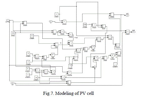
| The PV panel modeling is done based on the equation stated above in section II. The MPPT algorithm generates the gate signals for the converter. The solar radiation for the system is given by step increment in radiation. The solar PV modeling with the modeling equation are shown in figure 7. |
 |
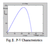
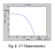
| The figures 8 and 9 shows the PV characteristics obtained for the photovoltaic system. The PV characteristics of the system are non-linear in nature. |
  |
| Simulation of Boost with voltage multiplier converter |
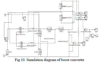 |
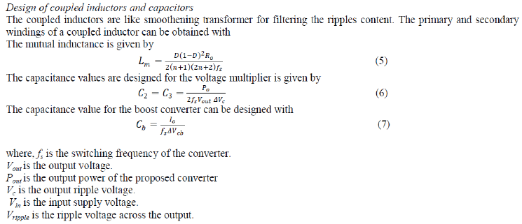
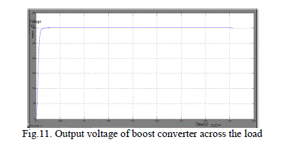
| The output voltage across the converter for an input of 30V from PV system is 300V. So the gain is 10 for a turns ratio of 1. The output of the converter is shown in figure 10.The output voltage obtained across the load is the sum of the voltages developed across the capacitors. The voltage stress across the switch can be minimized. Also improves the gain and efficiency of the converter. The converters are provided with capacitances of values C1=470μF, C2=C3=Cb=220μF and load resistance R= 200Ω respectively. The pulses for the converter provided by P & O algorithm are based on transport delay. The converter works in continuous mode of operation, with a phase shift of 180âÃÂð and duty cycle greater than 0.5 |
 |
| c.Simulation of Multilevel inverter |
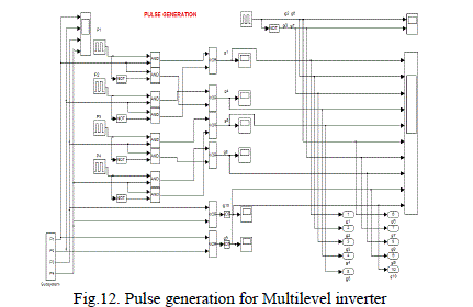
| The inverter is a hybrid combination of cascaded H bridge inverter with phase disposition principle. The output of which is shown in figure 13.The reference sine wave of fundamental frequency is compared with four carrier triangular waves for generating basic pulses for the inverter. The triangular pulses are selected for a frequency of 25kHz. This topology can be used for power factor correction, the figure shows the current and voltages are in phase. The figure 12 shows the gating pulses for the inverter to operate. |
 |
 |
CONCLUSION |
| The boost converter and inverter integration with photovoltaic system is discussed. The gain and efficiency of the converter depends on the design, components used in the topology. The maximum power can be tracked with MPPT technique in the photovoltaic system for better performance. The design of the converter determines the performance of the system. The smaller value of duty cycle increases the robust working of the photovoltaic system. This system are advantages for various application such as reduction in conduction losses, voltage stress across the switch, leakage energy recycling, better efficiency and gain. The dc-dc converter discussed is integrated with hybrid cascaded H bridge for connecting the R-L load. |
References |
|