ISSN ONLINE(2278-8875) PRINT (2320-3765)
ISSN ONLINE(2278-8875) PRINT (2320-3765)
R.Dharmaprakash1 and Joseph Henry2
|
| Related article at Pubmed, Scholar Google |
Visit for more related articles at International Journal of Advanced Research in Electrical, Electronics and Instrumentation Engineering
Induction motors are used in most of the industrial applications due to its reliability, robustness, low cost and low maintenance. The main focus of this paper is investigation of high performance control methods which are being applied to make induction motor with good dynamic behaviour. The high performance control methods investigated are vector control and direct torque control. The dynamic behaviour of induction motor is studied for step change in speed and step change in load. The results of Matlab/Simulink simulations of both methods are presented. The relative advantages and disadvantages of each method were highlighted.
Keywords |
| Induction motor, variable speed, electrical drives, vector control, direct torque control |
INTRODUCTION |
| AC motors are classified into two major types, synchronous and asynchronous or induction motors. Induction motors have been widely used in industrial applications due to the reliability, robustness low cost and greatly reduced maintenance compared to other motors. Electrical motors take more than 50 percent of the total electrical power in the industries. In this more than 65 percent of the power is used by induction motor drives [1]. Even the principle of induction motor being known for more than 100 years, still a considerable progress is being achieved [2]. This is due to the advances in materials, power electronics and high speed digital controllers[1-2]. High performance motor applications require a fast torque response. Generally DC motors were preferred. Previously, torque response control was a problem in induction motors. The advancements in power electronic devices and high speed controllers provide the fast torque response control of induction motors [3, 9]. These controllers provide good steady state performance and transient behaviour [3]. |
| The control methods of induction motor can be divided into two types as scalar control method and vector control method. In scalar control method magnitude and frequency are controlled. It is a simple method to implement. But due to the coupling effect it gives poor torque response. Vector control method has been proposed in early 1970s. It is also known as field oriented control. In this method, both magnitude and phase alignment of vector variables are considered. It provides fast torque response. In vector control, motor equations are transformed into field coordinates which is corresponding to the decoupled torque production in separately excited DC motor [4]. In mid of 1980s an advanced scalar control method known as direct torque control was introduced. Direct torque control method utilised the vector relationships, but replaces the coordinate transformation concept of vector control method. It also provides the fast torque response [5]. |
| In this paper, the vector control or field oriented control and direct torque control methods are investigated. A brief overview of the operation of each method and the Matlab-Simulink simulation results are presented. A comparison of the two methods is included. |
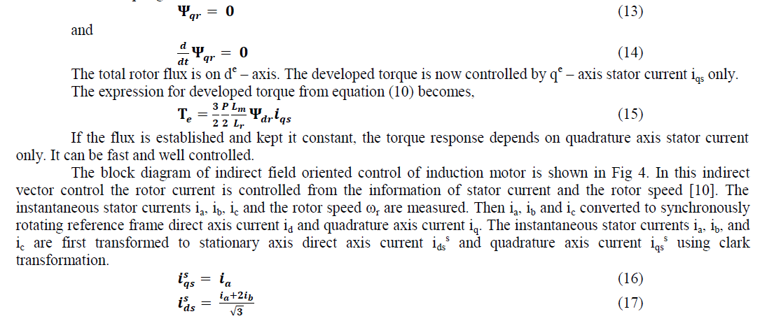
DYNAMIC MODEL OF INDUCTION MOTOR |
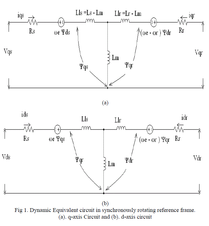
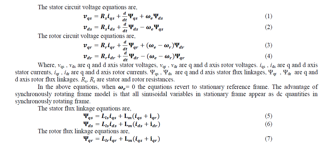
| The dynamic model of three phase induction motor can be written with the variables referred to the d-q synchronously rotating reference frame [5]. The dynamic d-q equivalent circuit of induction motor in synchronously rotating reference frame is given in Fig 1. |
 |
 |
 |
INDIRECT FIELD ORIENTED CONTROL |
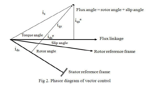
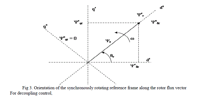
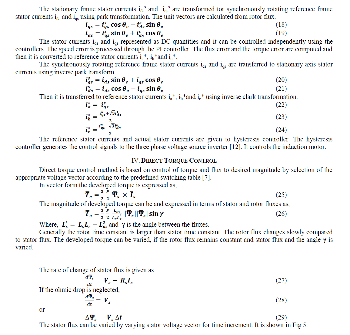
| The vector control or field oriented control consists of controlling stator currents [6], [8]. This control is based on transforming three phase time dependent variable into two phase time invariant system. This leads DC motor-like control to induction motor. Field oriented control requires two constant inputs, torque component and flux component. In synchronously rotating reference frame, iqs and ids are analogous to torque and flux components. The stator currents are controlled in such manner that iqs delivers the desired torque while ids maintains the rotor flux. Speed error is used to generate desired torque. The phasor diagram of vector control is shown in Fig 2. |
 |
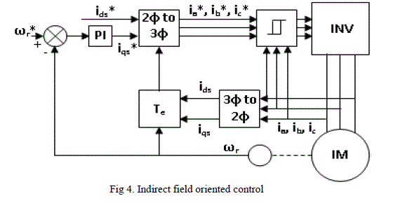
| Indirect vector control is same as direct vector control except the unit vectors are generated in feed forward manner. Indirect vector control method is used in more number of industrial applications. |
 |
 |
 |
 |
 |
 |
 |
 |
 |
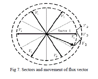
| Based on flux angle, taking the first sector as – 30° to + 30°, the six sectors are shown in Fig 7. |
 |
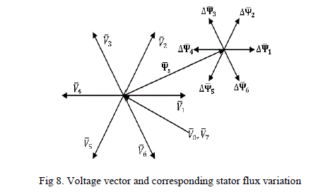 |
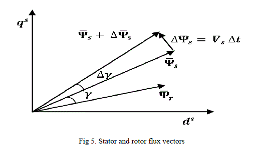
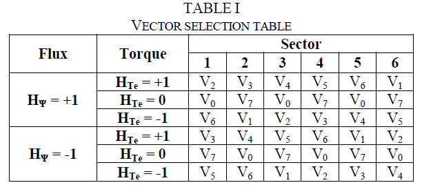
| The voltage vector and corresponding stator flux variation is shown in Fig.8. To vary the magnitude of stator flux and developed torque, the voltage vector is selected based on equation (26), Fig 7 and Fig 8 [5]. If the stator flux vector is in first sector. To increase the flux and torque voltage vector V2 is selected. To decrease the flux and increase the torque voltage vector V3 is selected. To decrease the flux and torque the voltage vector V5 is selected. And to increase the flux and decrease the torque the voltage vector V6 is selected. |
| The voltage vectors to be selected for variation of stator flux and torque in each sector is identified as above and it is given in Table I [5], [10], [11]. |
 |
SIMULATION |
| To compare the vector control and direct torque control of induction motor, simulations are carried out by using Matlab / Simulink. For simulation a 50HP, 460V, 60 Hz star connected three phase induction motor has been taken and its rated parameters are Rs = 0.087, Rr = 0.228, Lls = 0.8 mH, Llr = 0.8 mH and Lm = 34.7mH. Motor inertia J = 1.662 kg m2, friction factor B = 0.1 Nm.sec/rad. |
| The simulations are carried out for three cases. |
| Case.1. Constant speed (1300 rpm) at no load, |
| Case.2. Step change in speed (600 to 1300 rpm at 3 sec) at no load. |
| Case.3. Step change in load (no load to 100 Nm) at constant speed (1300 rpm). |
| The speed response, stator current response and the torque response are plotted for vector control and direct torque control methods. |
RESULTS |
| Results of simulations of vector control and direct torque control are shown in Fig.9 - 11. |
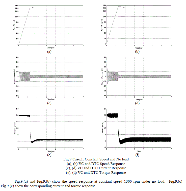 |
| Fig.9.(a) and Fig.9.(b) show that the induction motor speed response using vector control has less overshoot during starting settling time compared with direct torque control. In vector control the speed reaches 1344.9 rpm at 1.3129sec and then settled in the steady state speed of 1300 rpm at 2.369 sec. In direct torque control the speed reaches 1366.5 rpm at 1.352 sec, and then it settled in the steady state speed of 1300 rpm at 2.828 sec. |
| Fig.9.(c) and Fig.9.(d) show that vector control has less stator current transient during starting. The torque response in Fig.9.(e) and Fig.9.(f) show that vector control and direct torque control has the torque ripple of 11Nm and 28Nm respectively. |
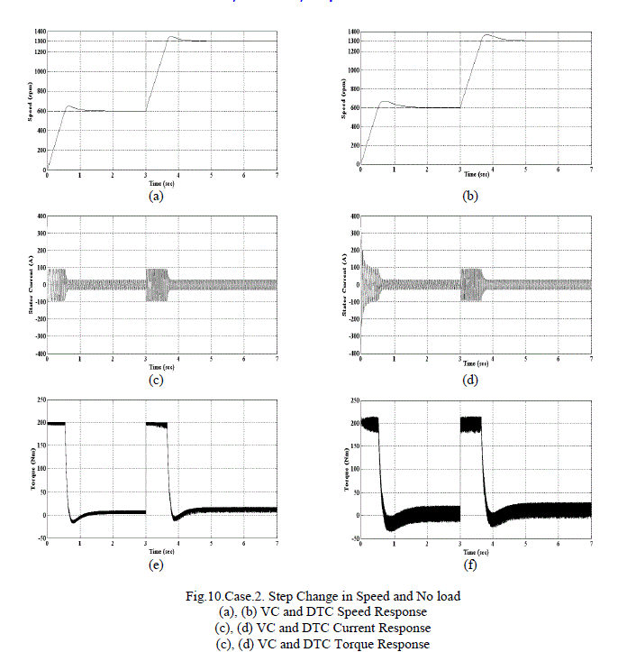 |
| Fig.10.(a) and Fig.10.(b) show the speed response for change in speed from 600 rpm to 1300 rpm at 3 sec, under no load. Fig.10.(c) – Fig.10.(e) show the corresponding current and torque response. |
| Fig.10.(a), (b) show that vector control has quick speed response than direct torque control. . In vector control the speed reaches 646.85 rpm at 0.663 sec and then settled in the steady state speed of 600 rpm at 1.84 sec. The reference speed is changed from 600 rpm to 1300 rpm at 3 sec. The speed reaches 1344.85 rpm at 3.773 sec, and then it comes to 1300 rpm at 5.92 sec. In direct torque control the speed reaches 669.27 rpm at 0.7056 sec and then settled in the steady state speed of 600 rpm at 2.595 sec. After the reference speed is changed, it reaches 1366.5 rpm at 3.818 sec, and then it comes to 1300 rpm at 6.474 sec. |
| Fig.10.(c), (d) show that vector control has less stator current transient during starting and speed change. The torque response shown in Fig.10.(e) and Fig.10.(f) show that direct torque control has more ripple. |
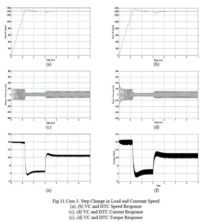 |
| Fig.11.(a) and Fig.11.(b) show the speed response for change in load from no load to 100 Nm at 3 sec and constant speed 1300 rpm. Fig.11.(c) – Fig.11.(e) show the corresponding current and torque response. |
| The speed decreases when the load is applied and then it comeback to the steady speed. After the load is applied, the speed decrease to 1275.5 rpm at 3.121sec and then settle in the steady state speed of 1300 rpm at 5.288 sec in vector control. In direct torque control the speed decrease to 1264.5 rpm at 3.175 sec and then settle in the steady state speed of 1300 rpm at 5.304 sec. |
| The torque response in Fig.11.(e) and Fig.11.(f) show that vector control and direct torque control has the torque ripple of 12 Nm and 33 Nm respectively. After load the torque ripple increased in both methods. The torque ripple is high in direct torque control. |
CONCLUSION |
| The result shows the performance similarities and differences between vector control and direct torque control methods. The dynamic response of both methods is good. Torque ripple is more in direct torque control method. It is due to the hysteresis band controller. The parameter sensitivity is low in direct torque control. The direct torque control is very simple. The vector control uses more transformation and the architecture is complex. Each method is having its advantages and disadvantages. So it is concluded as the selection of control method is based on particular application of the drive. |
References |
|