This paper presents a new parallel pipelined architecture to compute Discrete Fourier Transform (DFT) using FFT architecture. This particular architecture uses folding transformation technique as well as register minimization technique for the design of FFT architecture. Novel architectures for the computation of complex and real valued fast Fourier transform are derived. Pipelining is used to reduce the power consumption. Parallel processing and pipelining exploits concurrency. Parallel processing also aids to the reduction of power consumption by reducing the supply voltage. The power consumption is reduced very effectively using the parallel architecture. This paper includes the comparative study of the speed of operation of FFT architectures using different multipliers.
Keywords |
| Fast Fourier Transform (FFT), folding, pipelining, parallel processing, register minimization, Vedicmultiplier,
Array multiplier, Baugh Wooley multiplier |
INTRODUCTION |
| Fast Fourier Transform (FFT) is a commonly used technique for the computation of Discrete Fourier Transform (DFT).
DFT computations are required in the fields like filtering, spectral analysis etc. to calculate the frequency spectrum or
to identify a system’s frequency response from its impulse response and vice versa. FFT is used in digital video
broadcasting and OFDM systems. Much research has been carried out to design pipelined architectures for computation
of FFT. The basic one is Radix-2 FFT. Based on the radix-2 FFT approach many algorithms have been developed
which includes radix-4 [4], split-radix [3], radix-2��[5] etc. A popularly known algorithm is cooley-Tukey radix-2 FFT
[2]. Radix-2 Multipath Delay Commutator (R2MDC) [6] is a classical approach for pipelined implementation of FFT
architecture. Radix-2 Single-path Delay Feedback (R2SDF) [7] is another approach with reduced memory obtained by
a standard usage of storage buffer in R2MDC. Most of the algorithms require hardware complexity and there is no
complete hardware utilisation. The basic aspects like high throughput and low power consumption are required to
speed and power requirements while keeping the hardware overhead to a minimum. This paper presents a technique to
design the architecture from FFT flow graph. Folding transformation [8], [10] and register minimization [8], [9], [11]
are the two important steps included in this FFT algorithm. |
| Folding Transformation is a technique in which the number of butterflies in the same column is mapped into one
butterfly unit. If we consider an FFT of size N, then 2-parallel architecture can be obtained if we consider the folding
factor to be N/2 or 4-parallel architecture if considering a folding factor of N/4. |
 |
 |
| By selecting the appropriate folding sets we can derive the FFT architectures. The folding sets are designed in a way to
reduce the number of storage elements and also the latency. The prior FFT architectures had no systematic way of
approach. This architecture simplifies the design of FFT and is a systematic approach towards the design of FFT with
arbitrary level of parallelism. These are derived either in Decimation-In-Time (DIT) or Decimation-In-Frequency (DIF)
flow graphs. FFT architectures can be derived for different radices. Parallel pipelined architectures for the computation
of Real valued signals (RFFT) based on radix-22 and radix-23 and different architectures for the computation of
complex valued signals (CFFT) are carried out earlier. This paper is organised into VII sections where section II
represents the folding transformation and register minimization based FFT architecture, section III and IV explains
about the proposed architecture for CFFT and RFFT respectively. In section VI a comparative study is conducted using
different multipliers. Finally, section VII certain conclusions are drawn from the comparative study. |
FFT ARCHITECTURE USING FOLDING |
| Folding Transformation as well as Register minimization techniques are used to obtain several FFT architectures.
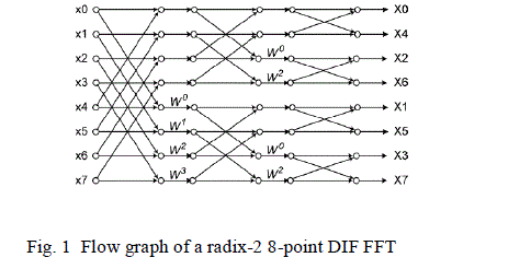
The whole process is explained with the help of 8-point radix-2 DIF FFT which can be extended to different radices.
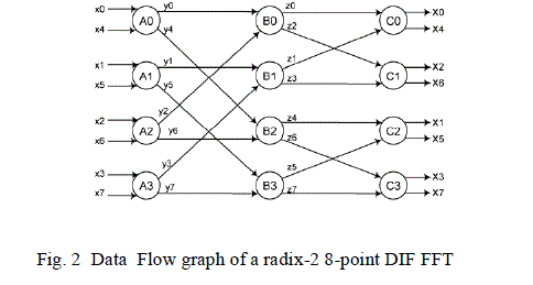
The flow graph of 8-point radix-2 DIF FFT is illustrated in Fig. 1. The twiddle factor indicates a multiplication by wkn
in between the stages. The Data Flow Graph of Fig.1 is shown in Fig. 2 where each node represents a computation. |
| DFG is subjected to folding transformation in order to derive a pipelined architecture. For this we require a folding set,
which is an ordered set of operations executed by the same functional unit. Every folding set contains number of entries
which are called the folding factors. A folding set may include null operations also. Consider two nodes represented as
U and V which are connected by an edge e with w(e) delays. The l-th iteration of these nodes be scheduled at Kl+u and
Kl+v where is the number of entries and u and v are the folding orders. The folding equation is represented as |
 |
| where PU is the number of pipeline stages. For the DFG in Fig. 2 consider the folding set shown below. |
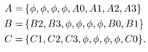 |
| We assume that the butterfly operations do not have any pipeline stages. Prior to deriving the folded architecture the
folded equations in (1) are to be written for all the edges as shown in (2). DF (A0→B0) = 2 means there is an edge with
weight 2 from node A to Bin the folded DFG. After obtaining the folding equations we have to determine whether the
folding sets are feasible or not. |
 |
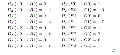 |
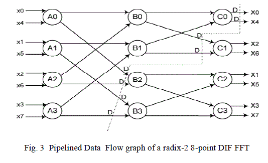
| In the equations obtained some negative delays are observed which needs to be removed. To make sure that the
folded architecture has non-negative number of delay the DFG can be pipelined as shown in Fig. 3. For the pipelined
DFG the folding equations are given by |
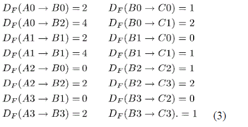 |
| From the above equations we can see 24 registers are required for implementing the folded architecture. As a next
step a technique called Lifetime analysis [8], [9], [11] is employed to design the architecture with the minimum number
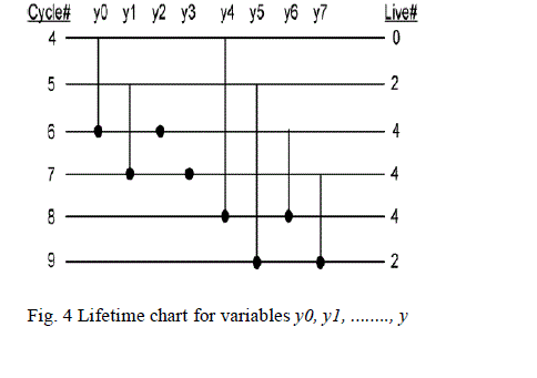
of delays. A lifetime chart is obtained as shown in Fig. 4 for one stage of the 8-point DFG. From the lifetime chart we
can analyse that we require only 4 registers to implement the design while considering the outputs of nodes A0, A1, A2
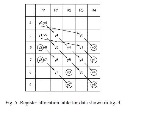
and A3 in the DFG instead of the 16 registers which was used in the straight forward implementation. Next step is
Register allocation as shown in Fig. 5. From the folding equations and the table in Fig. 5 the architecture in Fig. 6 can
be derived. We can see from the folding sets that half of the time null operations are being executed and therefore the
hardware utilization is only 50%. |
 |
 |
 |
ARCHITECTURE WITH COMPLEX INPUTS (CFFT) |
| This section presents parallel architecture for complex valued signals based on radix-2 and radix-23 algorithms. The
approach presented in the previous section can be used to derive all these architectures. |
| A. 2-parallel radix-2 FFT Architecture |
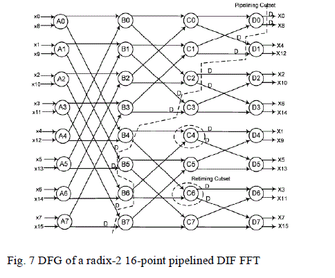
| Fig. 7 shows the DFG of radix-2 DIF FFT for N=16 where all the nodes represent radix-2 butterfly operations.
Consider the folding sets |
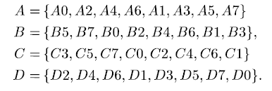 |
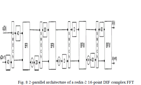
| We can observe that here the folding sets does not contain any null operations. Thus we can derive the folded
architecture using the steps used in the previous section. In this architecture two input samples are processed at the
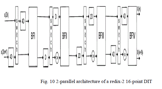
same time. The hardware utilization is 100%. The architecture is shown in Fig. 8. In a similar way the 2-parallel
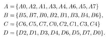
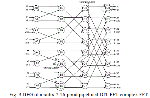
architecture for radix-2 DIT FFT can also be derived using the folding set below. Fig. 9 represents the pipelined DFG
and fig. 10 shows the 2-parallel architecture. |
 |
 |
 |
 |
 |
| B. 4-Parallel Radix-2 FFT Architecture |
| Consider the folding set shown below using which a 4-parallel architecture can be derived. |
 |
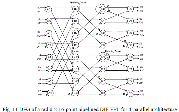
| Using the algorithm used in the previous section we can obtain the pipelined DFG as in Fig. 11 and the 4-parallel
architecture as shown in Fig. 12 |
 |
 |
 |
ARCHITECTURES WITH REAL INPUTS (RFFT) |
| The input sequence x[n] for RFFT is considered to be real. If x[n] is real then output X[k] is symmetric. ie ; X[Nk]=
X*[k].
Using this property (N/2) - 1outputs can be removed which are redundant. A new approach in identifying these
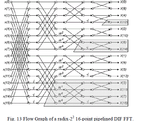
redundant samples is proposed in [12]. The shaded regions of the Fig. 13 can be removed as they are all redundant
samples identified using the approach in [12] and only N/2 + 1 outputs of the FFT are required. |
| A. 2-Parallel Radix-2 Architecture |
| The DFG of this architecture is same as Fig. 7 and the folding set is as follows. |
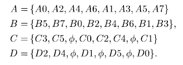 |
| The architecture is similar to that shown in Fig. 8 except that first two stages will contain a real data path. The hardware
complexity is same as that of the CFFT. |
| B. 2-parallel Radix-22 Architecture |
| Two different scheduling approaches are used to derive two different architectures. It is mainly done by changing the
folding order of the butterfly nodes. |
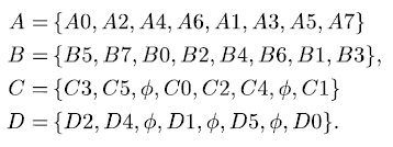
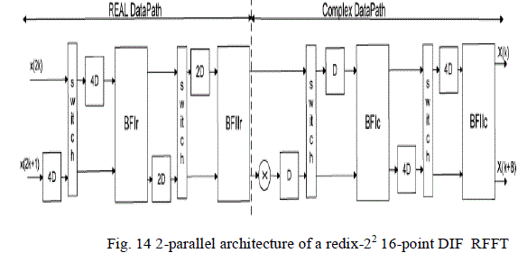
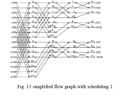
| 1) Scheduling Method 1: The parallel-pipelined architecture is shown in Fig. 14 obtained from Fig. 13. The
folding set used is [1], [8]. The scheduling for the architecture is shown in Fig. 15. |
 |
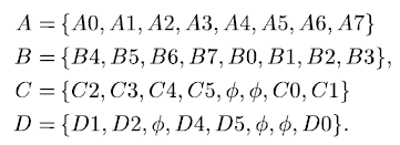
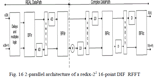
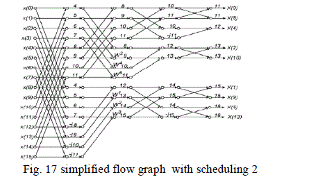
| 2) Scheduling Method 2: This method reduces the number of delay elements and slightly modifies the
architecture [1], [8]. The folding set is as follows. |
 |
 |
 |
| The modified architecture is shown in Fig. 16 and the scheduling is shown in Fig. 17. |
MULTIPLIERS |
| Multipliers play a very important role in FFT architectures as it consumes most of the time. The speed of FFT greatly
depends on the multiplier employed in the design. Array Multipliers are used for various architectures due to its regular
structure where the multiplier circuit is based on add and shift algorithm. Baugh Wooley Multipliers are generally
known for its high speed and low power consumption. And Vedic Multipliers are a particular type of multipliers which
are high speed complex multipliers which is an ancient methodology of Indian Mathematics. The speed of FFT
architectures varies with the use of different multipliers. |
COMPARISON AND ANALYSIS |
| Researchers had generated parallel pipelined FFT architecture that achieves complete hardware utilization with reduced
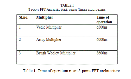
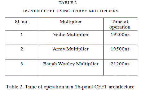
power consumption [1] when compared to the serial architectures. Here different multipliers including Vedic multiplier,
Array Multiplier and Baugh Wooley Multiplier are being employed in separate designs and compared for Time of
operation and comparison tables are generated for different parallel FFT architectures. The analysis is done using
Modelsim 6.5e. |
 |
 |
 |
 |
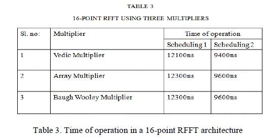 |
| From the tables we can understand that Vedic multiplier is very much efficient in terms of speed of operation than the
other two multipliers. |
CONCLUSION |
| This paper presents a pipelined parallel FFT architecture which has a lesser power consumption compared to serial
FFT architectures. It also has the advantage of complete hardware utilization. For a high speed Pipelined parallel FFT
architecture a Vedic multiplier can be employed in the particular design. Thus an efficient design can be obtained in
terms of power and speed. |
References |
- Pipelined Parallel FFT Architectures via Folding Transformation, ManoharAyinala, Student Member, IEEE, Michael Brown, and Keshab K. Parhi, Fellow, IEEE transactions on very large scale integration (vlsi) systems, vol. 20, no. 6, June 2012.
- J. W. Cooley and J. Tukey, âÃâ¬ÃÅAn algorithm for machine calculation of complex fourier series,âÃâ¬Ã Math.Comput., vol. 19, pp. 297âÃâ¬Ãâ301, Apr. 1965.
- P. Duhamel, âÃâ¬ÃÅImplementation of split-radix FFT algorithms for complex, real, and real-symmetric data,âÃâ¬Ã IEEE Trans. Acoust., Speech, Signal Process., vol. 34, no. 2, pp. 285âÃâ¬Ãâ295, Apr. 1986.
- A. V. Oppenheim, R.W. Schafer, and J. R. Buck, Discrete-Time Signal Processing, 2nd ed. Englewood Cliffs, NJ: Prentice-Hall, 1998.
- S. He and M. Torkelson, âÃâ¬ÃÅA new approach to pipeline FFT processor,âÃâ¬Ã in Proc. of IPPS, 1996, pp. 766âÃâ¬Ãâ770.
- L. R. Rabiner and B. Gold, Theory and Application of Digital Signal Processing. Englewood Cliffs, NJ: Prentice-Hall, 1975.
- E. H. Wold and A. M. Despain, âÃâ¬ÃÅPipeline and parallel-pipeline FFT processors for VLSI implementation,âÃâ¬Ã IEEE Trans. Comput., vol. C-33, no. 5, pp. 414âÃâ¬Ãâ426, May 1984.
- Keshab K Parhi, VLSI Digital Signal Processing Systems: Design and implementation, , Hoboken, NJ: Wiley.1999.
- K. K. Parhi, âÃâ¬ÃÅCalculation of minimum number of registers in arbitrary life time chart,âÃâ¬Ã IEEE Trans. Circuits Syst. II, Exp. Briefs, vol. 41, no. 6, pp. 434âÃâ¬Ãâ436, Jun. 1995.
- K. K. Parhi, C. Y. Wang, and A. P. Brown, âÃâ¬ÃÅSynthesis of control circuits in folded pipelined DSP architectures,âÃâ¬Ã IEEE J. Solid-State Circuits, vol. 27, no. 1, pp. 29âÃâ¬Ãâ 43, Jan. 1992.
- K. K. Parhi, âÃâ¬ÃÅSystematic synthesis of DSP data format converters using lifetime analysis and forward-backward register allocation,âÃâ¬Ã IEEE Trans. Circuits Syst. II, Exp. Briefs, vol. 39, no. 7, pp. 423âÃâ¬Ãâ440, Jul. 1992.
- M. Garrido, K. K. Parhi, and J. Grajal, âÃâ¬ÃÅA pipelined FFT architecture for real-valued signals,âÃâ¬Ã IEEE Trans. Circuits Syst. I, Reg. Papers, vol. 56, no. 12, pp. 2634âÃâ¬Ãâ 2643, Dec. 2009.
|