ISSN ONLINE(2278-8875) PRINT (2320-3765)
ISSN ONLINE(2278-8875) PRINT (2320-3765)
G.TAMIZHARASI1, S.KATHIRESAN2
|
| Related article at Pubmed, Scholar Google |
Visit for more related articles at International Journal of Advanced Research in Electrical, Electronics and Instrumentation Engineering
In this era conservation of electricity plays a main role. Equally generating electricity is also very important. There are number of ways to produce electricity. Out of that, wind energy is one of the ways. But it cannot produce electricity as per the need. To overcome that, a new approach is necessary and that is establishing a scooped wind mill. It could help to generate more electricity and cater to the need. The main aim of this paper is to improve the efficiency of the wind mill by following the new design, scoop technology that leads to improvement of the efficiency of the wind turbine.
INTRODUCTION |
| A new modified blade is to be used in a wind mill instead of the type of blade that is used at present. This blade can be useful to generate more electricity. By using normal blade we get a minimum percentage of electricity from wind mills. This is so because there is no variation in the force of the wind that strikes against the blade. For example if the wind blows 40 km/hr, it strikes against the blade with the same force. But the same wind dashes against the scooped blade with extra force. |
| When a scooped blade is used, there is a variation in the force of the wind that dashes against the blade. This increases the speed of the blade and so the blade rotates faster than that of the previous blade. This project is to prove how the scooped blade is superior to the flat blade and how it is beneficial. |
 |
| TOWERS |
| The tower on which a wind turbine is mounted is not just a support structure. It also raises the wind turbine so that its blades safely clear the ground and so it can reach the stronger winds at higher elevations. The towers without guy wires are called freestanding towers. Something to take into consideration about a tower is that it must support the weight of the windmill along with the weight of the tower. Maximum tower height is optional in most cases, except where zoning restrictions apply. Towers can be constructed of a simple tube, a wooden pole or a lattice of tubes, rods, and angle iron. Large wind turbines may be mounted on lattice towers, tube towers or guyed tilt-up towers. It must be strong enough to support the wind turbine and to sustain vibration, wind loading and the overall weather elements for the lifetime of the wind turbine. Tower costs will vary widely as a function of design and height. |
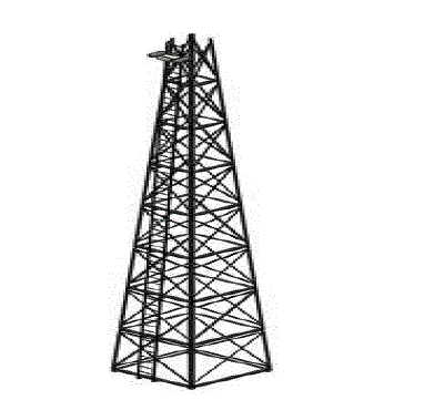
| LATTICE TOWER |
| Lattice tower were common back in the old farm days, they are kind of towers you see most wind powered well pumps on. They have a larger foot print for their size requiring a larger foundation. They are supported by three of four legs with interlock braces up and down the tower. This type of tower is a good option if you are looking for a small and cheap wind turbine tower. |
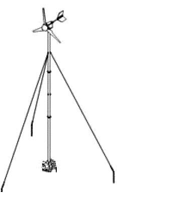 |
| GUYED TOWER |
| A guyed tower has a centre pole with guyed wires supporting and holding it in place. You will typically find guyed towers for radio and television antennas. These towers are typically the easiest and cheapest to build. However, they are ugly and intrusive and require more space than a free standing tower. |
| TILT-UP GUYED TOWER |
| Tilt-up tower are nice for erecting and maintain and are the most popular for home wind turbine builders. They have a pivot at the bottom allowing them to bend up and down from the ground. A tilt-up guyed tower is a popular choice for home builders. |
| BLADES |
| The blades are perhaps the most important part of our wind turbine - they are the ‘engine’ that drives our dynamo. These wind turbine blades have a simple airfoil and when finished they’ll look (and work) a bit like airplane wings. This design is a simple one. It’s a compromise we made keeping the following things in mind: efficiency, strength, cost and availability of materials, and ease of construction. The ‘front’ of the blade is the surface that faces towards the wind; it’s flat, scooped and angled a bit. |
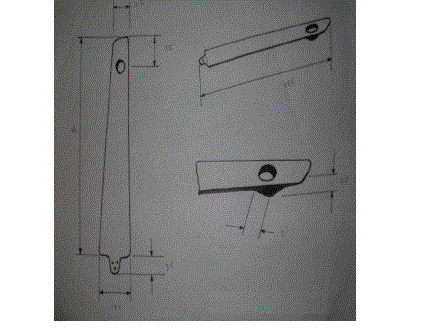 |
| The ‘back’ of the blade is facing away from the wind and it’s flat in shape. The portion of the wind turbine that collects energy from the wind is called the rotor. The rotor usually consists of two or more wooden, fiberglass or metal blades which rotate about an axis (horizontal or vertical) at a rate determined by the wind speed and the shape of the blades. The blades are attached to the hub, which in turn is attached to the main shaft. |
| When wind moves over the turbine blades, it generates a lift. The lift makes the blades rotate and hence rotate the shaft. The rotating shaft moves a magnetic field in the dynamo, which in turn creates electricity. |
| NUMBER OF BLADES |
| The ideal wind generator has an infinite number of infinitely thin blades. In the real world, more blades give more torque, but slower speed, and most alternators need fairly good speed to cut in. 2 bladed designs are very fast (and therefore perform very well) and easy to build, but can suffer from a chattering phenomenon while yawing due to imbalanced forces on the blades. 3 bladed designs are very common and are usually a very good choice, but are harder to build than 2-bladed designs. Going to more than 3 blades results in many complications, such as material strength problems with very thin blades. Even one-bladed designs with a counterweight are possible. |
| BALANCING THE BLADES |
| If the wind rotor is not balanced then the wind generator will shake as it spins. After hours and days of shaking, parts will begin to drop off. Usually the tail is first to go. It is important to balance the wind rotor carefully. Here are some steps to balance the rotor blades: |
| 1. Support each blade at the root, and weigh the tip. Each blade should have the same tip weight. In order to do this test accurately we support all of the blade roots in exactly the same way. Make a jig which supports the blade root at the centre of the rotor. |
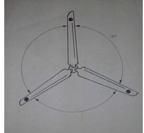
| 2. Mount the blades on the rotor hub accurately. If there are three blades, then the distance between the blade tips must be the same for each pair. If there are two blades then the line between the tips must pass exactly through the centre of the rotor. |
| 3. When the blades are mounted on the wind generator, check that the tips pass though exactly the same space as they turn. One blade tip should not be in front or behind the others. |
 |
| MOUNTING THE ROTOR BLADES |
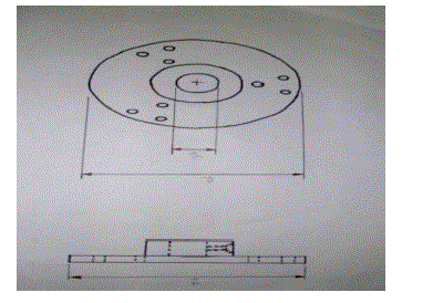
| The blades must be securely bolted to a central hub which fits on the PMG. Do not bolt the blades directly to the front magnet-rotor, because the gyroscopic forces on the blades will stress the magnet rotor and cause the magnets to hit the stator. The blades are ‘sandwiched’ between two steel plates. This makes a simple, strong hub. |
 |
WORKING PRINCIPLE |
| The wind turbine basically works the opposite of a fan. Instead of using electrical energy to generate wind energy, turbines use wind energy to generate electrical energy. These turbines are computer-controlled to improve its efficiency, and to prevent them from breaking down. |
| Firstly, as the wind is blown, an Anemometer is used to measure the speed and direction of the wind. As the turbine is moved into the direction of the wind, the Blades begin to rotate. As it rotates, the energy is then transmitted into a Gearbox. The gearbox is a set of gears that formulates the Generator to revolve. The Generator is what converts mechanical energy into electrical energy. The generator is made of opposite magnetic fields. As the magnets revolve, it produces an invisible magnetic field, which consists of electrical energy. Coils of wire, which harnesses the electrical energy, is therefore converted into electricity. |
| THE OPERATING PRINCIPLES OF WIND TURBINES |
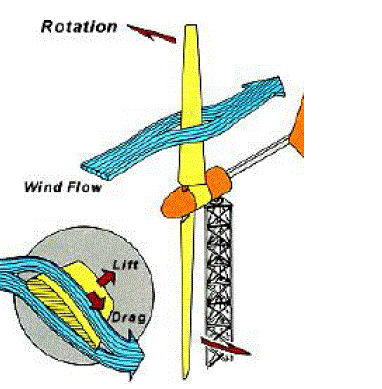 |
| The “Lift” and “Drag” Aerodynamic Principles of a Rotor Blade |
| When a gust of wind passes over the airfoil shaped blade, it passes faster over the upper or curved part of the airfoil. This causes a low-pressure area above the airfoil. The difference in pressure between the top and bottom surfaces results in a force, called aerodynamic lift. |
| If this were an aircraft wing, this force would cause the airfoil to “rise”, lifting the airfoil, and therefore the aircraft, off the ground. Since the blades of a wind turbine are permanently attached to the hub at its centre, the lift force causes rotation about the hub. In addition to lift force, a “drag” force perpendicular to the lift force impedes rotor rotation. The prime objective in a wind turbine design is to have a relatively high lift-to-drag ratio, and this ratio can be varied depending on the length of the blade to maximize the turbine’s energy output at various wind speeds. |
OPERATING CHARACTERISTICS |
| CUT-IN SPEED |
| Cut-in speed is the minimum wind speed at which the wind turbine will generate usable power. This wind speed is typically between 7 and 10 mph. |
| RATED SPEED |
| The rated speed is the minimum wind speed at which the wind turbine will generate its designated rated power. For example, a "10 kilowatt" wind turbine may not generate 10 kilowatts until wind speeds reach 25 mph. Rated speed for most machines is in the range of 25 to 35 mph.At wind speeds between cut-in and rated, the power output from a wind turbine increases as the wind increases. The output of most machines levels off above the rated speed. Most manufacturers provide graphs, called "power curves," showing how their wind turbine output varies with wind speed. |
| CUT-OUT SPEED |
| At very high wind speeds, typically between 35 and 80 mph, most wind turbines cease power generation and shut down. The wind speed at which shut down occurs is called the cut-out speed. Having a cut-out speed is a safety feature which protects the wind turbine from damage. Shut down may occur in one of several ways. In some machines an automatic brake is activated by a wind speed sensor. Some machines twist or "pitch" the blades to spill the wind. Still others use "spoilers," drag flaps mounted on the blades or the hub which are automatically activated by high rotor rpm's, or mechanically activated by a spring loaded device which turns the machine sideways to the wind stream. Normal wind turbine operation usually resumes when the wind drops back to a safe level. |
| TIP SPEED RATIO |
| The ‘tip-speed-ratio’ is the speed at which the blade tip should run compared to the Wind speed. The shaft speed in revolutions per minute (rpm) depends on the tip speed and the diameter. rpm = wind speed x tip-speed-ratio x 60 / (diameter x P) The main reason why the two blade rotor can work at higher tip-speed-ratio is that it only has two blades. The smaller, three bladed rotor will have a slower tip-speed, but will run more smoothly because it has three blades. |
| BETZ LIMIT |
| It is the flow of air over the blades and through the rotor area that makes a wind turbine function. The wind turbine extracts energy by slowing the wind down. The theoretical maximum amount of energy in the wind that can be collected by a wind turbines rotor is approximately 59%. This value is known as the Betz limit. If the blades were 100% efficient, a wind turbine would not work because the air, having given up all its energy, would entirely stop. In practice, the collection efficiency of a rotor is not as high as 59%. A more typical efficiency is 35% to 35%. A complete wind energy system, including rotor, transmission, generator, storage and other devices, which all have less than perfect efficiencies, will (depending on the model) deliver between 10% and 30% of the original energy available in the wind. |
CONCLUSION |
| From this paper, we come to know that we get more power from scooped blade wind mill than from the normal blade wind mill. If we use high voltage capacity dynamo, we can get more power which is sufficient for household bulbs and fans. The Future will likely to bring bigger and better platform for the wind turbine. Many new wind turbine models are being built. So this scooped wind mill will play a vital role in the producing of electricity than that of the normal one. Thus we conclude that it will be accepted and implemented in the course of time. |