In modern days, we must use various high-tech machineries and equipments to get our jobs done and make the life easier. These machineries should be controlled by the house owner from any location as the house owner might be away from house at workplace or travelling in a different place in the weekend. Thus a system of remote monitoring and controlling are very much necessary. Smart home is one of these types of system equipped with home appliances which we wish to control home appliances smartly from anywhere. Some products are commercially available which allow remote home appliance controlling through internet which is undoubtedly emerging. But it lacks the true sense of real mobility and security, making the remote home appliance controlling a limited term than it is supposed to be. In search of a true remote and adequately secure solution to be really effective and practicable, mobile telephony is better than any other solutions. Mobile phones have become almost an inseparable part of civil lives today. In this work we introduce a new mechanism so that the ordinary services of the mobile phones can be leveraged to communicate with and control the home appliances and make our homes a really smart one.
INTRODUCTION |
| Now-a-days home is equipped with various machineries and equipments which provides various facilities to human
life. Most used devices at home are electrical light, electric fan, air conditioner and refrigerator. These are to be controlled and
operated by human beings. However this may not be possible all the time. Operator may not be at home and may be
somewhere in a different place and if the necessity arises to control these home appliances there must be some source to control
and monitor the home appliances. This necessity made the invention of new product which controls the home appliances.
We introduce a new mechanism using mobile phones which control home appliances and make our work easier. Home
appliances controlling using WINDOWS PHONE7 application creates a friendly environment to the user. Main advantages of
this system is reducing power wastage saving time and also for security purposes. One of the security applications is automation
of door locks. This door locks can be operated using this smart phone application. Operator can control switching appliances
that is they can be made on or off, can change temperature of room from any place, control lighting and can perform many other
tasks. |
WINDOWS PHONE-7 APPLICATION |
| A. INTRODUCTION: |
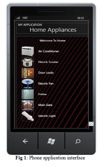
| This application runs on windows mobile platform, the application has a graphical interface provided with convenient
radio buttons to operate their status on a single click, for few appliances like Air conditioners were even provided with the real
time status, so we may easily operate this application to control the home appliances, the image preview is here provided below. |
| B. TOOLS: |
| Various tools used for the development of windows phone 7 application are |
| • Visual studio 2010 express for windows phone |
| • Windows phone emulator resources |
| • Silver light 4 tools for Visual studio |
| • XNA game studio 4.0 |
| • Microsoft expression blend for windows phone |
| C. DESIGN: |
| All the tools are to be installed for developing the windows phone7 application. LAUNCH the visual studio 2010 and
create a new Silverlight for windows phone application. The tool will be providing all the design options. For example as shown
in below. |
 |
| HARDWARE |
| A. MICROCONTROLLER AT89S52 |
| The AT89S52 is a low-power, high-performance CMOS 8-bit microcontroller with 8k bytes of in system
programmable flash memory. The device is manufactured using Atmel’s high-density non-volatile Memory technology and is
compatible with the industry-standard 80C51 instruction set and pin out.
The on-chip Flash allows the program memory to be reprogrammed in system or by a conventional non-volatile
memory programmer. By combining a versatile 8-bit CPU with in-system programmable Flash on a monolithic chip
(monolithic chip is integrated circuit which contains active and passive devices, the chip will be made with “planar
technology”) , the Atmel AT89S52 is a powerful microcontroller which provides a highly-flexible and Cost-effective solution to
many embedded control applications. |
| The AT89S52 provides the following standard. |
| 1) FEATURES: |
| • 8K bytes of Flash, |
| • 256 bytes of RAM, |
| • 32 I/O lines, |
| • Watchdog timer, |
| • Two data pointers, |
| • Three 16-bit timer/counters, |
| • A six-vector two-level interrupt Architecture, |
| • A full duplex serial port, |
| • On-chip oscillator. |
| In addition, the AT89S52 is designed with static logic for operation down to zero frequency and supports two software
selectable power saving modes. The Idle Mode stops the CPU while allowing the RAM, timer/counters, serial port, and
Interrupt system to continue functioning. The Power-down mode saves the RAM con-tents but freezes the Oscillator, disabling
all other chip functions until the next interrupt or hardware reset. MCS-51 devices have a separate address space for Program
and Data Memory. Up to 64K bytes each of external Program and Data Memory can be addressed. |
| The WDT is intended as a recovery method in situations where the CPU may be subjected to Software upsets. The
WDT consists of a 14-bit counter and the Watchdog Timer Reset (WDTRST) SFR. The WDT is defaulted to disable from
exiting reset. To enable the WDT, a user must write 01EH and 0E1H in sequence to the WDTRST register (SFR location
0A6H). When the WDT is enabled, it will increment every machine cycle while the oscillator is running. The WDT timeout
period is dependent on the external Clock frequency. There is no way to disable the WDT except through reset (either hardware
reset or WDT Overflow reset). When WDT over-flows, it will drive an output RESET HIGH pulse at the RST pin. |
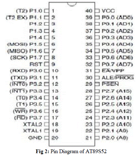
| 2) PIN CONFIGURATION: |
 |
| B. POWER SUPPLY |
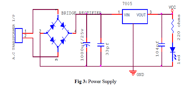
| In our project we used 9 volts transformer for continuous power supply. Because of this we can have continuous
power, hence we use it. Otherwise if we use a battery sometimes the total currents will loss so that’s way we are using A.C
Transformer. A.C transformer is giving the input to Bridge Rectifier. Bridge Rectifier converts A.C to D.C. After that we are
using one filter capacitor 1000uf/25v electrolytic capacitor .We are connecting this capacitor in parallel section. The main
purpose of this capacitor is if there is any alternate peaks we need to reduce that peaks nothing but filtering those ripples. After
that we are using LM7805 Regulator Most digital logic circuits and processors need a 5 volt power supply. To use these parts
we need to build a regulated 5 volt source. We make a 5 volt power supply, The LM7805 is simple to use. First connect the
positive lead of our unregulated DC power supply input pin, connect the negative lead to the Common pin and then when we
turn on the power, we get a 5 volt supply from the Output pin. Here we are using one red colour led to indicate the power. |
 |
| C. SERIAL COMMUNICATION: |
| Data is transferred by computers in two ways. They are serial data transfer and parallel data transfer. In parallel data
transfer data is transmitted to the devices which are at smaller distances that are devices which are few feet away. In printers
and hard disks parallel data transfer is used. Serial communication is used for transferring data to devices which are located
many meters away. |
| When microcontroller communicates with other devices then data is provided in the form of bytes in ASCII code format.
In printers the data is received from the 8-bit data bus and this byte sized data is to be converted into single bits for serial
communication. Parallel in serial out shift register converts byte of data into serial bits then output of this shift register is serial
bits and these serial bits can be transmitted over single bit line. At the receiver side serial in parallel out shift register is used to
group individual bits into bytes. They are two methods in serial communication one is synchronous method and the other
method is asynchronous method. In synchronous method a block of data is transmitted at a time while in asynchronous method
a single byte is transferred at a time. Software can be written to both these methods but program is very long so IC chips are
designed by the manufactures for serial communication. |
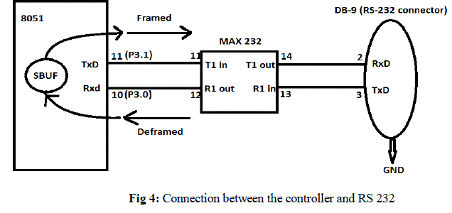
| Two pins of the microcontroller AT89S8252 are used for transmitting and receiving data serially. TXD pin is used for
transmitting data serially. RXD pin is used for receiving data serially. These two pins RXD and TXD are connected to port3 of
microcontroller. |
| D. RS232: |
| RS232 called as a standard interface allows compatibility for data communication and it supports data interface. Rs232
is used for connecting serial devices. It acts as a physical interface for low speed communication between computers and other
related devices. Data is transmitted and received serially in RS232. For full duplex communication independent channels are
established Signals of RS23 are represented with voltage levels. The input and output voltage levels are not compatible with
transistor-transistor logic family. These voltage levels are represented with respect to common level. The idle state represents
negative signal level with respect to common and active state represents positive level with respect to ground. RS232 interface
has common ground between DTE and DCE. It has hand shaking lines primarily used with modems and this specifies
communication protocol. |
| In RS232 +3 to +12 volts represents ON state or 0-state condition and -3 to -12 volts represents OFF state or 1-state
condition. Zero level represents OFF state and lesser positive potentials represent ON state. Thus 5v dc power is enough for
driving RS232 circuits. The output signal level swings between +12v and -12v. Voltage range from +3v to -3 v is called dead
area and this dead area absorbs line noise. RS232 port can support less power to other devices.
As RS232 is not compatible with TTL voltage converters are used as interconnection in between RS232 and microcontrollers.
The voltage converter used is MAX232. |
 |
| E. RELAY: |
| An electrical switch that is operated by an electromagnet such as solenoid. When a small current passes through the
electromagnets coiled wire, it produces a magnetic field that attracts a movable iron bar, causing it to pivot and open or close
the switch. |
| 1) Operation: An electromagnetic relay is a type of electrical switch controlled by an electromagnet. The
electromagnetic relay is used in a variety of applications, including alarms and sensors, signal switching, and the
detection and control of faults on electrical distribution lines. The electromagnetic relay was invented in 1835, and its straightforward function has not changed much since. Consumers interact with the electromagnetic relay in a variety of
forms daily, from timed office lights to test buttons and other quality control devices. The core of the
electromagnetic relay, naturally, is an electromagnet, formed by winding a coil around an iron core. When the coil is
energized by passing current through it, the core in turn becomes magnetized, attracting a pivoting iron armature. As
the armature pivots, it operates one or more sets of contacts, thus affecting the circuit. When the magnetic charge is
lost, the armature and contacts are released. Demagnetization can cause a leap of voltage across the coil, damaging
other components of the device when turned off. Therefore, the electromagnetic relay usually makes use of a diode to
restrict the flow of the charge, with the cathode connected at the most positive end of the coil. |
| F. OPTO COUPLER: |
| Opto Coupler is a solid state component in which light emitter, the light path and light detector are all enclosed within the
component and cannot be altered externally. Usually Intra Red Emitting Diode (IRED) can be used as a light emitter. Photo
transistor can be used as a light detector. |
| 1) PRINCIPLE: There is one way of transfer of electrical signal from LED (IRED), to photo transistor without any
electrical connection between the input and output circuitry. The degree of isolation between input and output depends
on the kind of materials used in the light path and on the distance between light emitter and light detector. If the
distance between emitter and detector is greater then and the isolation is better but current transfer ratio i.e., ratio of
detector to emitter current is lower. |
| 2) WORKING: The coupler may be operated as switch in which cause both the LED and photo transistor are normally
OFF. A pulse of current through LED causes the transistor to be switched ON for the duration of the pulse. Operation
as a linear coupler is also possible by setting up a bias current in the LED. The signal is then capacitive coupled to the
LED and causes its brightness to increase or decrease thus the photo transistor receives a light signal which increases
or decreases linearly around the constant bias level. |
| G. GSM INTRODUCION: |
| GSM(Global System for Mobile Communications), is the standard developed by the European Telecommunications
Standard Institute to describe protocols for second generation digital cellular networks used by mobile phones. Previously, there
are first generation analog cellular networks which are replaced by these 2G networks and these networks are optimized for full
duplex voice telephony. |
| GSM is a trademark which is owned by GSM Association. One of the key features of GSM is the Subscriber Identity Module,
commonly known as a SIM card. The SIM is a detachable smart card containing the user's subscription information and phone
book. This allows the user to retain his or her information after switching handsets. Alternatively, the user can also change
operators while retaining the handset simply by changing the SIM. Some operators will block this by allowing the phone to use
only a single SIM, or only a SIM issued by them; this practice is known as SIM locking. |
| 1) SYNTAX AND COMMANDS |
| AT COMMAND SYNTAX: |
| The "AT" or "at" prefix must be set at the beginning of each command line. To terminate a command line enter <CR>. |
| Commands are usually followed by a response that includes.”<CR><LF><response><CR><LF>” |
| Throughout this document, only the responses are presented, <CR><LF> are omitted intentionally. |
| The AT command set implemented by SIM300 is a combination of GSM07.05, GSM07.07 and ITU-T recommendation V.25ter
and the AT commands developed by SIMCOM. |
| Note: Only enter AT command through serial port after SIM300 is power on and Unsolicited Result Code “RDY” is
received from serial port. And if unsolicited result code”SCKS: 0” returned it indicates SIM card isn’t present. |
| All these AT commands can be split into three categories syntactically: “basic”, “S parameter”, and “extended”.
These are as follows: |
| BASIC SYNTAX: |
| These AT commands have the format of “AT<x><n>”, or “AT&<x><n>”, where “<x>”is the command, and
“<n>”is/are the argument(s) for that command. An example of this is “ATE<n>”, which tells the DCE whether received
characters should be echoed back to the DTE according to the value of “<n>”. “<n>” is optional and a default will be used if
missing. |
| S PARAMETER SYNTAX:These AT commands have the format of “ATS<n>=<m>”, where “<n>” is the index of the S register
to set, and “<m>”is the value to assign to it. “<m>” is optional; if it is missing, then a default value is assigned. |
| SMS AT COMMANDS: |
| AT+CMGD: DELETE SMS MESSAGE |
| AT+CMGF: SELECT SMS MESSAGE FORMAT |
| AT+CMGL: LIST SMS MESSAGES |
| AT+CMGR: READ SMS MESSAGE |
| AT+CMGS: SEND SMS MESSAGE |
| AT+CMGW: WRITE SMS MESSAGE TO MEMORY |
| AT+CMSS: SEND SMS MESSAGE FROM STORAGE |
| AT+CMGC: SEND SMS COMMAND |
| AT+CNMI: NEW SMS MESSAGE INDICATION |
| AT+CPMS: PREFERRED SMS MESSAGE STORAGE |
| AT+CRES: RESTORE SMS SETTINGS |
| AT+CSAS: SAVE SMS SETTINGS |
| AT+CSCB: SELECT CELL BROADCAST SMS MESSAGES |
| AT+CSDH: SHOW SMS TEXT MODE PARAMETERS |
| AT+CSMP: SET SMS TEXT MODE PARAMETERS |
| AT+CSMS: SELECT MESSAGE SERVICE |
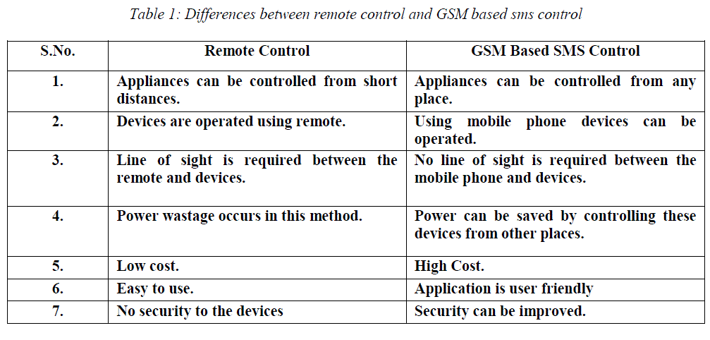 |
PROPOSED METHOD |
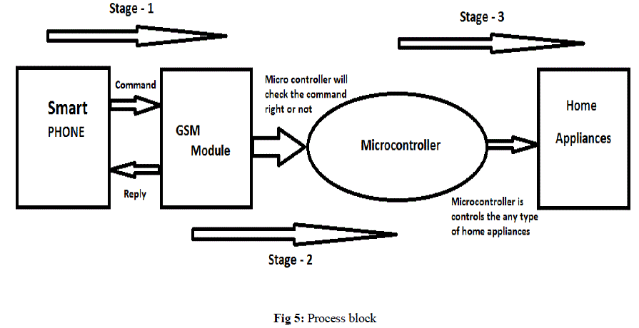 |
| STAGE-1 |
| Stage-1 is communication between the smart phone and the GSM module. |
| • The smart phone will be sending the command to GSM module. |
| • GSM module will be sending the Acknowledgement back to the smart phone. |
| STAGE-2 |
| Stage-2 is communication between the GSM module and microcontroller. |
| • GSM module will be sending the command to the microcontroller. |
| • The controller will be checking the command. |
| STAGE-3 |
| Stage-3 is communication between the microcontroller and home appliances. |
| • The microcontroller will be control the home appliances. |
| • Using this microcontroller control the any type of home appliances. |
| STAGE-1 |
| 1. Open the application page in the smart phone where you can find the appliances list. |
| 2. Select the appliances which you want to control. |
| 3. If you select the air conditioner interface may be opened as above. |
| 4. Select the options provided above which are different for different appliances. |
| 5. The AT commands will be generated automatically in the background. |
| 6. If we click on the send button the command will be sent to the GSMMODULE at home through SMS service. |
| 7. The message is transferred to the microcontroller from GSMMODULE and it works accordingly, and the
microcontroller sends the acknowledgement back. |
| STAGE-2 |
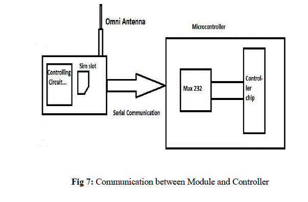
| 1. Instructions are sent to controller chip through MAX232 using RS232 cable. |
| 2. MAX232 is a voltage level converter. |
| 3. Communication between MAX232 and RS232 is serial communication. |
| 4. Pin 3.0 receives data and Pin 3.1 transmits data in microcontroller AT89S52. |
| STAGE-3 |
| Different types of home appliances are controlling with the different types of drivers. Those are Relay, Optocoupler,
and etc….. |
| 1. Relay is used for ON and OFF purposes. |
| 2. Optocoupler is used for controlling speed, for example it is used for controlling the speed of fan. |
| 3. These drivers are interconnected with microcontroller and home appliances. |
| LIGHT CONTROL: |
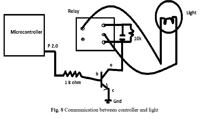
| 4. Data is transmitted from microcontroller to relay. |
| 5. Light is controlled using relay. It can be made ON or OFF. |
| 6. When 0 volts is given to relay then light will be OFF. |
| 7. When positive voltage is supplied to relay then light will be ON. |
| 8. The status of the appliance is sent by the microcontroller through GSM module to mobile. |
| FAN CONTROL: |
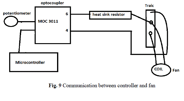
| 9. Data is transmitted from microcontroller to Opto Coupler. |
| 10. Fan is controlled using Opto Coupler. It can be made ON or OFF and speed of the fan can also be regulated. |
| 11. When 0volts is supplied to Opto Coupler then fan will be in OFF state. |
| 12. When positive potential is supplied to Opto Coupler then fan will be in ON state. |
| 13. Speed of the fan is regulated using potentiometer. |
| 14. This potentiometer is connected to Opto Coupler. |
| 15. Status of fan is obtained from microcontroller to mobile via GSM module. |
RESULT ANALYSIS |
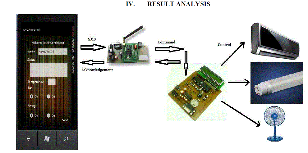 |
| Fig 6: Overview of Home Appliances |
| A. COMMUNICATION BETWEEN MODULE AND CONTROLLER |
 |
| B. LIGHT CONTROL |
 |
| C. FAN CONTROL |
 |
CONCLUSION |
| In this work we introduced how to control the home appliances using the smart phone application. From above discussion we
conclude that as technology is vast growing and can have many facilities suggested above such as controlling the home
appliances from remote areas, also overcome fire accidents if we implement some more changes which is more helpful. |
References |
- Kenneth J.Ayala, âÃâ¬ÃÂThe 8051 MicrocontrollerâÃâ¬ÃÂ.Edition.3,pp.185-197,2000
- Lawrence Harte, Bruce Bramley, Mike Davis ,âÃâ¬ÃÅIntroduction to GSMâÃâ¬ÃÂ,Edition.3
- Vladimir Gurevich, âÃâ¬ÃÂElectric Relays Principles and applicationsâÃâ¬ÃÂ, pp.193-269,2006
- Jochen Schiller, âÃâ¬ÃÂMobile CommunicationâÃâ¬ÃÂ,Edition.2,pp.96-130,2006
- Charles Petzold, âÃâ¬Ã Programming Windows Phone 7âÃâ¬ÃÂ,pp.393-589,2010
- Jacob Milliman, âÃâ¬ÃÅElectronic devices and circuitsâÃâ¬ÃÂ,Edition.2,pp.592-629,2008
- Brian Faucher, âÃâ¬ÃÂWindows phone7 application developmentâÃâ¬ÃÂ,pp.3-37,2011
- Nick Randolph, Christopher Fairbairn, âÃâ¬ÃÂProfessional Windows Phone 7 Application Development: Building Applications and Games Using Visual Studio, Silverlight, and XNAâÃâ¬ÃÂ,pp.123-149,2010
- Rob Cameron, âÃâ¬ÃÂPro Windows Phone 7 DevelopmentâÃâ¬ÃÂ,edition.2,pp.1-305,2011
- Windows Phone 7 Application Development - from internet Microsoft windows.
- Phone 7 development center-from internet.
- Yuksekkaya B, Kayalar A.A, Tosun M.B, Ozcan M.K, Alkar A.Z, "A GSM, internet and speech controlled wireless interactive home automation system," Consumer Electronics, IEEE Transactions on Consumer Electronics,Vol.52,no.3,pp.837-843,Aug.2006
- RifatShahriyar, EnamulHoque, S.M. Sohan, IftekharNaim, âÃâ¬ÃÅRemote Controlling of Home Appliances using Mobile TelephonyâÃâ¬ÃÂ, International Journal of Smart Home, Vol. 2, No. 3, July, 2008
- Malik Sikandar Hayat Khiyal, Aihab Khan, and ErumShehzadi âÃâ¬ÃÅSMS Based Wireless Home Appliance Control System (HACS) for Automating Appliances and SecurityâÃâ¬ÃÂ, Issue in Information Science and Information Technology Vol.6, pp 887-894, 2009.
- Jia-Ren Chang Chien, Cheng-Chi Tai âÃâ¬ÃÅThe Information Home Appliance Control SystemâÃâ¬ÃâA Bluetooth Universal Type Remote ControllerâÃâ¬Ã Proceedings of the 2004 IEEE. International Networking, Sensing & Control. Taipei, Taiwan, Vol. 1,pp. 399-400, March 21-23. 2004
|