ISSN ONLINE(2278-8875) PRINT (2320-3765)
ISSN ONLINE(2278-8875) PRINT (2320-3765)
Sriram DivyaVani1 and K. Gunaprasad2
|
| Related article at Pubmed, Scholar Google |
Visit for more related articles at International Journal of Advanced Research in Electrical, Electronics and Instrumentation Engineering
Now-a-days due to the shortage of electric power and rising cost of non-renewable energy resources generating electric power from the renewable energy resources such as PV modules are increasing day to day. This paper presents non-isolated, high step-up dc-dc converter with hybrid transformer with for low voltage renewable energy resources applications. The proposed converter utilizes hybrid transformer to transfer the inductive and capacitive energy simultaneously, achieving high step-up voltage with smaller sized magnetic component, the turn-off loss of switch is minimized, increasing the efficiency of the converter under all load conditions. By changing the input voltage the voltage stresses on the active switch and diodes are maintained at low level and are independent as a result of the resonant capacitor transferring energy to the output of the converter. Due to high system efficiency as well as ability to operate with a wide variable input voltage, the proposed dc-dc converter is an attractive design for alternative low dc voltage energy sources, such as solar PV modules and fuel cells.
Keywords |
| High boost ratio dc-dc, high efficiency, hybrid transformer, photovoltaic (PV) module. |
INTRODUCTION |
| Due to the rising costs and limited amount of Non-renewable energy sources, there is an increasing demand for the utilization of renewable energy sources such as photovoltaic modules. Integrating the power from the PV module into the existing power distribution infrastructure can be achieved through power conditioning systems (PCS). |
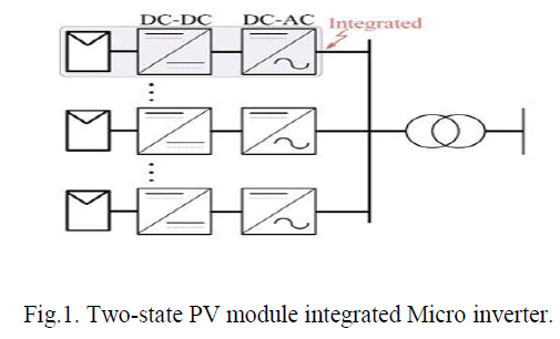 |
| Typical PCS can be accomplished using a single stage or a double-stage as shown in Fig. 1.The double-stage PCS consists of a dc-dc conversion stage that is connected to either a low power individual inverter or a high-power centralized inverter that multiple converters could connect to. The dc-dc conversion stage of the PCS needs a high efficiency and high boost ratio dc-dc converter to increase the low dc input voltage from the PV panel to a higher dc voltage. |
| The high boost ratio dc–dc converter for such systems can be isolated or non-isolated [1]; however, transformerisolated converters tend to be less efficient and more expensive due to the increased manufacturing costs. A nonisolated dc–dc converter with a high boost ratio would be advantageous for a two-stage PCS [1] because it can be easily integrated with current PV systems while reducing the cost and maintaining a high system efficiency. Due to the different output voltages from the PV panel, it would be useful to have a system with a high efficiency over the entire PV voltage range to maximize the use of the PV during different operating conditions. |
A. LITERATURE SURVEY |
| To obtain a high step-up gain with high efficiency in non-isolated applications, a high step-up method based on isolated-type converters is introduced. By stacking the secondary side of an isolated converter in addition to its primary side, a high step-up conversion ratio as well as distributed voltage stress can be achieved. Moreover, a careful selection of an isolated converter can provide zero-voltage switching (ZVS), continuous input current and reduced reverse recovery on diodes. Depends on a conventional voltage doubler rectifier boost-integrated half-bridge converter, the proposed converter satisfies all these features, which make it apt for high step-up applications. |
B. HIGH BOOST DC-DC CONVERTER |
| Of the many high boost ratio dc-dc converter topologies, a combination of flyback and boost converters was proposed to increase the boost ratio without significant cost and efficiency penalties is shown in fig.2. |
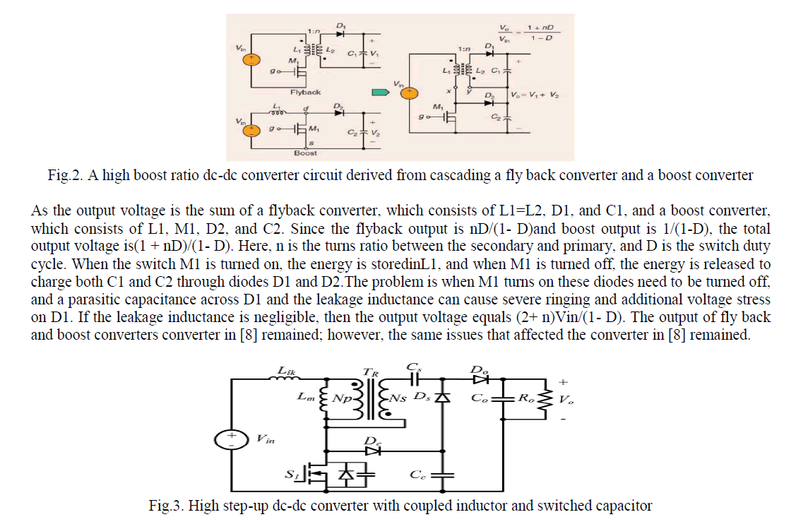 |
| By adding a switched-capacitor in series with the energy transformer path, a new improved high boost ratio dc–dc converter with coupled-inductor and switched capacitor, as shown in Fig. 3, was introduced. With the switchedcapacitor inserted between the primary side and secondary side of the coupled-inductor, the boost ratio was increased and the output diode voltage stress was reduced closer to that of the output dc bus voltage. However, the magnetic core was not fully utilized because it functioned more as an inductor than as a transformer. Light load efficiency of the converter is also reduced because switching losses were more dominant under light load conditions. |
| For PV module converter, the high efficiency over a wide load range and input voltage range is extremely important. In this paper, a high boost ratio dc-dc converter with hybrid transformer is presented to achieve high system level efficiency over wide input voltage and output power ranges. By adding a small resonant inductor and reducing the capacitance of the switched-capacitor in the energy transfer path, a hybrid operation mode can be achieved. The inductive and capacitive energy can be transferred simultaneously to the high voltage dc bus increasing the total power delivered decreasing the losses in the circuit. Output voltage is compared with a reference voltage to turn on the switch so as to keep the output voltage constant. |
PROPOSED METHOD |
A. PROPOSED CONVERTER TOPOLOGY AND OPERATION ANALYSIS |
| Fig.4 shows the circuit diagram of the proposed converter. C is the input capacitor; HT is the hybrid transformer with the turns ratio 1:n; S1 is the active MOSFET switch; D1 is the clamping diode, which provides a current path for the leakage inductance of the hybrid transformer when S1 is OFF, Cc captures the leakage energy from the hybrid transformer and transfers it to the resonant capacitor Cr by means of a resonant circuit composed of Cc , Cr , L r , and Dr ; L r is a resonant inductor, which operates in the resonant mode; and Dr is a diode used to provide an unidirectional current flow path for the operation of the resonant portion of the circuit. Cr is a resonant capacitor, which operates in the hybrid mode by having a resonant charge and linear discharge. The turn on of Dr is determined by the state of the active switch S1. Do is the output diode similar to the traditional coupled inductor boost converter and Co is the output capacitor. Ro is the resistive load. |
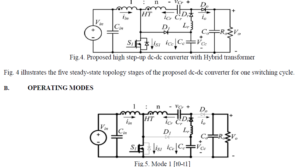 |
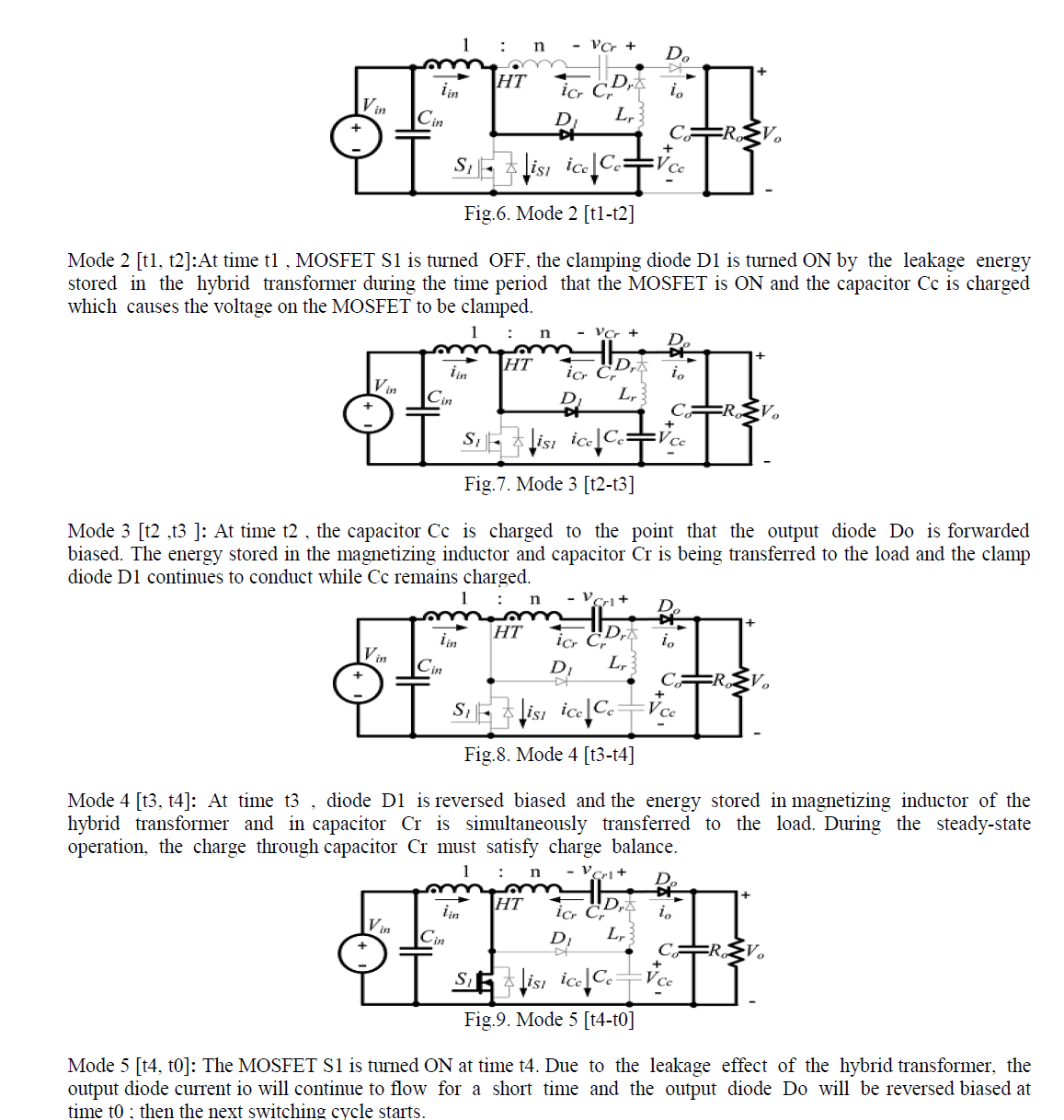
| Mode 1 [t0, t1]: In this period , MOSFET S1 is ON, the magnetizing inductor of the hybrid transformer is charged by input voltage, Cr is charged by Cc , and the secondary reflected input voltage nVin of the hybrid transformer together by the resonant circuit composed of secondary side of the hybrid transformer, Cr , Cc , Lr ,and Dr . The current in MOSFET S1 is the sum of the resonant current and linear magnetizing inductor current. |
 |
C. ANALYSIS AND ADVANTAGES OF THE PROPOSED CONVERTER |
| Fixed Voltage Stresses of the Power Devices: |
| The voltage stresses of MOSFET S1 and clamping diode D1 are obtained |
 |
| From the above equations it is obvious that all the voltage stresses of the switches are independent of input voltage and load conditions. In other words, all the voltage stresses of the switches are optimized based on the output voltage and the turns ratio of the transformer. |
D. ADVANTAGES OVER CONVENTIONAL NON RESONANT HIGH STEP- UP CONVERTER: |
| In the proposed high boost ratio dc d c converter the inductive and capacitive energy can be transferred simultaneously to the high voltage dc bus increasing the total power delivered decreasing the losses in the circuit. As a result of the energy transferred through the hybrid transformer that combines the modes where the transformer operates under normal conditions and where it operates as a coupled-inductor, the magnetic core can be used more effectively and smaller magnetics can be used. The continuous input current of the converter causes a smaller current ripple than that of previous high boost ratio converter topologies that used coupled inductors. The lower input current ripple is useful in that the input capacitance can be reduced and it is easier to implement a more accurate MPPT for PV modules. The conduction losses in the transformer are greatly reduced because of the reduced input current RMS value through the primary side. The voltage stress of the switch is always at a low voltage level and independent of the input voltages. |
TWO-PHASE INTERLEAVED EXTENSION |
| In order for the proposed converter to be used in higher power level conversion applications, the interleaving method applicable to the traditional high boost ratio PWM dc–dc converter can be employed. This gives the advantages of standard interleaved converter systems such as low-input current ripple, reduced output voltage ripple, and lower conduction losses. |
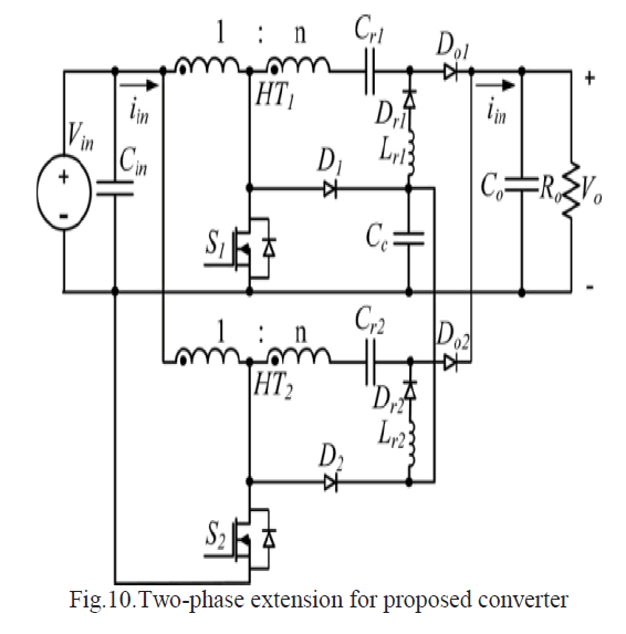 |
| Fig.10 represents two-phase extension of proposed converter. The difference between standard interleaved converters and the proposed interleaved converter is that the clamping capacitor Cc can also be shared by the interleaved units reducing the total number of components in the system. |
SIMULATION RESULTS |
| In order to verify the effectiveness of the proposed converter, the converter was designed in MATLAB/SIMULINK environment. |
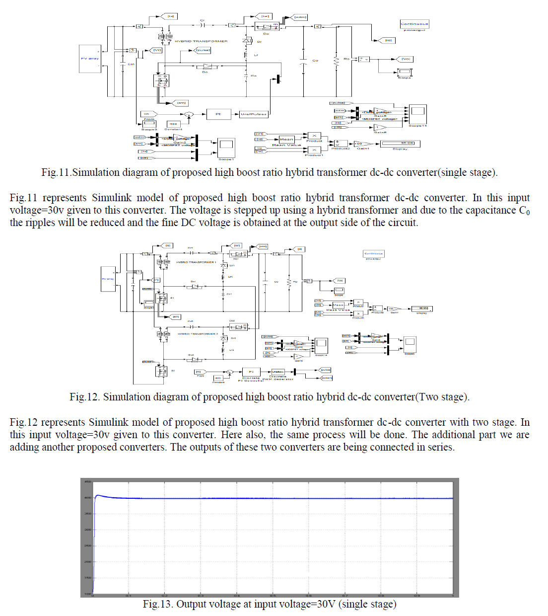 |
| Fig.13 shows the output voltage waveform of proposed high boost ratio hybrid transformer dc-dc converter with single stage which is seen that the voltage gradually increasing from 0v to 390v |
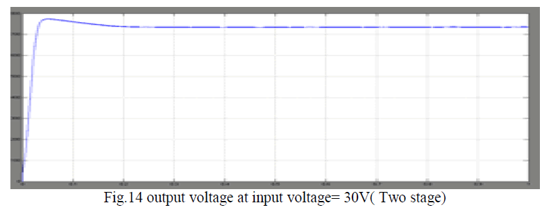 |
| Fig.14 shows the output voltage waveform of proposed high boost ratio hybrid transformer dc-dc converter with two stage which is seen that the voltage gradually increasing from 0v to 730v |
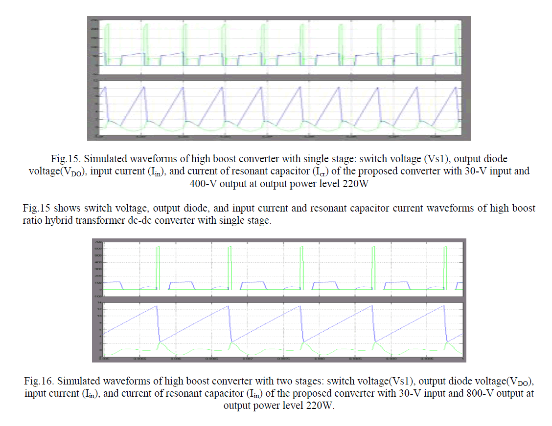 |
| Fig.16 shows switch voltage, output diode, and input current and resonant capacitor current waveforms of high boost ratio hybrid transformer dc-dc converter with two stage. |
CONCLUSION |
| This paper presents highly efficient high boost ratio hybrid transformer DC-DC converter for photovoltaic module applications with following features and benefits: |
| • This converter transfers the capacitive and inductive energy simultaneously to increase the total power delivery reducing losses in the system. |
| • The conduction loss in MOSFET is reduced as a result of the low-input RMS current and switching loss is reduced with a lower turn-off current. |
| • With these improved performances, the converter can maintain high efficiency under low output power and low-input voltage conditions. |
References |
|