Zigbee is a wireless technology that utilizes radio communication with 802.15.4 an IEEE standard. Presently, the widespread deployment of RFID technologies may generate new threats to security and user privacy. One of the main drawbacks of RFID technology is the weak authentication systems between reader and a tag. In general, “weak” authentication systems that either leak the password directly over the network or leak sufficient information while performing authentication allow intruders to deduce or guess the password. In this paper, we study the Zigbee based mutual authentication scheme. A hardware implementation of the mutual authentication protocol for the RFID system is proposed. The proposed system was implemented using a general purpose micro controller 89c51. The system has been successfully implemented in hardware using two zigbee transievers.
Keywords |
| Micro controller, Zigbee, mutual authentication, RS232c |
INTRODUCTION |
| RADIO-FREQUENCY identification (RFID) is a contactless identification technology that enables remote and automated
gathering and sending of information between RFID tags or transponders and readers or interrogators using a wireless link.
In recent years, RFID technology has gained rapid acceptance as a means to identify and track a wide array of
manufactured objects [1]–[3]. An RFID system is composed of three main components: tag, reader, and back-end database.
RFID tags come in a range of forms and can vary in storage capacity, memory type, radio frequency, and power capability.
An RFID tag typically consists of an integrated circuit for handling data and an antenna for receiving and transmitting a
radio-frequency signal. |
| In the commercial setting, RFID tags contain an electronic product code (EPC) that can uniquely identify each and
every tagged item [4]. The RFID tag stores its unique EPC with related product information inside the tag’s memory and
sends these data whenever the reader requests them. The reader reads data from and writes data to tags by broadcasting the
RF signals. After a reader queries a tag and receives information from the tag, the reader forwards the information to a
backend database. The back-end server plays an essential role in checking the validity of the tags or reader, which is very
important for privacy protection and security issues. RFID standards are a major issue in securing high investments in
RFID technology on different levels (e.g., interface protocol, data structure, etc.). There are two competing initiatives in the
RFID standardization arena: ISO [5] and EPC Global [4], [6]. The EPCglobal Class-1 Generation-2 (C1G2) ultrahigh
frequency (UHF) RFID standard defines a specification for passive RFID technology and is an open and global standard.
The EPC C1G2 standard specifies the RFID communication protocol within the UHF spectrum (860 to 960 MHz). The
standard specifies that a compliant RFID tag should contain a 32-b kill password (Kpwd) to permanently disable the tag
and a 32-b access password (Apwd). The reader then performs a bitwise XOR of the data or password with a random
number from the tag to cover-code data or a password in EPC Gen 2. However, the EPC C1G2 standards do not fully
support privacy invasion and data security issues. The simple kill and access commands specified in EPC C1G2
specifications are not enough to provide secure authentication function and data/privacy protection. EPC C1G2 provides
only very basic security tools using a 16-b pseudorandom number generator (PRNG) and a 16-b cyclic redundancy code
(CRC). Despite many prospective applications, RFID technology has several privacy-related problems such as data leakage
and data traceability, which should be resolved before RFID’s pervasive employment. Many methods have been proposed
to enhance the security of RFID systems, and the research for RFID security is quite extensive and growing [7]–[16]. Most hash-based RFID protocols for mutual authentication have been proposed in the literature [17]–[19]. Juels proposed a
solution based on the use of pseudonyms, without any hash function [20]. This mutual authentication protocol is based on a
short list of pseudonyms that are stored on a tag. To resist cloning and eavesdropping, this protocol requires extra memory
on the tag and needs a way to update the tag’s pseudonym list. The communication cost is relatively high because of the tag
data updates, which limits the practicality of this scheme. A set of lightweight challenge response authentication algorithms
for a low-cost tag is proposed in[21]. Although these can be used in authenticating the tags, the algorithms may be easily
broken by a powerful adversary. Due to very limited computational capability in a low-cost RFID tag, only 250–4 K logic
gates can be devoted to security-related tasks. Many studies on light authentication protocols that use only efficient bitwise
operations (such as XOR, AND, OR, etc.) on tags have been proposed [22]–[24]. Konidala et al. [10] proposed a protocol
based on XOR operation and tag’s access and kill passwords for the tag–reader mutual authentication scheme. However,
this approach has not been implemented in hardware. The rest of this paper is organized as follows. In Section II, we
present the background and previous work on the RFID reader-to-tag authentication protocol. The pad-generation function
is discussed in Section III. Section IV shows the implementation results of the mutual authentication scheme using zigbee .
Finally, we conclude the paper in Section V. |
RELATED WORK |
| A. EPC Class-1 Gen-2 Standard |
| An access password is required before data are exchanged between a reader and a single tag. The access password is a 32-b
value stored in the tag’s reserved memory. If this password is set, then the reader has to have the valid password before the
tag will engage in a secured data exchange. These passwords can be used in activating kill commands to permanently shut
down tags, as well as for accessing and relocking a tag’s memory. To cover-code data or a password in Gen 2, a reader first
requests a random number from the tag. The reader then performs a bitwise XOR of the data or password with this random
number and transmits the cover-coded (also called ciphertext) string to the tag. The tag uncovers the data or password by
performing a bitwise XOR of the received cover-coded string with the original random number. In addition, the tag
conforming to the EPC C1G2 standard can support only a 16-b PRNG and a 16-b CRC checksum that are used to detect
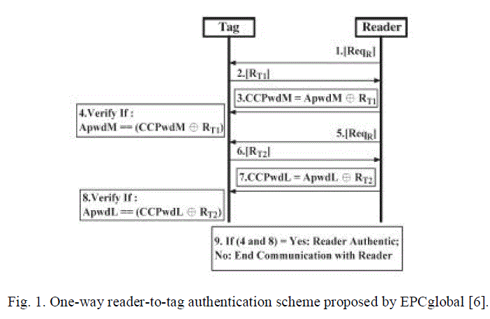
errors in the transmitted data [4], [6]. Fig. 1 describes the EPCglobal C1G2 communication step between a reader and a tag.
A detailed description of each step is as follows. |
| 1) The interrogator issues a Req_RN and sends a request message to a tag. |
| 2) The tag responds by backscattering a new 16-b random number RN16. |
| 3) The interrogator then generates a 16-b ciphertext string comprising a bitwise XOR of the 16-b word to be transmitted
with this new RN16, both MSB first, and issues the command with this ciphertext string as a parameter. |
| 4) The tag decrypts the received ciphertext string by performing a bitwise XOR of the received 16-b ciphertext string with
the original RN16. |
| 5) The interrogator issues a Req_RN to obtain a new RN16. |
| 6) The tag responds by backscattering a different RN16. |
| 7) The interrogator then transmits a 16-b ciphertext string generated from the 16 LSBs of the tag’s access password XORed
with the RN16 generated at step 6). |
| 8) The tag performs a bitwise XOR operation of the received 16-b ciphertext string and the RN16 to decrypt the received
ciphertext string for verification. |
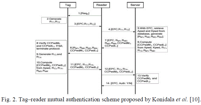
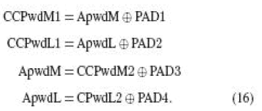
| B. Konidala et al. Mutual Authentication Scheme |
| Konidala et al. [10] utilized the tag’s 32-b access and kill passwords in achieving tag–reader mutual authentication. Their
scheme uses two rounds of PadGen to compute a cover-coding pad. The first round performs PadGen over the access
password, while the second round performs PadGen over the kill password. |
 |
| The PadGen function is used to create the 16-b pads for “cover coding” the access password. In the Konidala et al. [10]
authentication scheme, as shown in Fig. 2, the reader issues a Req_RN command to the acknowledged tag. The tag then
generates two 16-b random numbers, namely, RT1 and RT2, and backscatters them with its EPC to
the reader. The reader forwards these messages to the manufacturer. The manufacturer matches the received EPC to retrieve
the tag’s access password (Apwd) and kill password (Kpwd) from the back-end database. The manufacturer then generates
and stores two 16-b random numbers, namely, RM1 and RM2. The “cover-coded passwords” for the 16 MSBs (CCPwdM1)
and the 16 LSBs (CCPwdL1) are computed by the PadGen (RTi,RMi) function for i = 1, 2. CCPwdM1, CCPwdL1, and
EPC along with four 16-b random numbers, namely, RM1, RM2, RM3, and RM4, generated by the manufacturer are
transmitted to the reader, which, in turn, forwards them to the tag for verification. To authenticate the tag, the tag generates
another two random numbers RT3 and RT4 along with the received RM3 and RM4 used to compute CCPwdM2 and
CCPwdL2 with the PadGen (RTi,RMi) function for i = 3, 4. CCPwdM2,
CCPwdL2, and EPC along with two 16-b random numbers, namely, RT3 and RT4, are transmitted to the reader, which, in
turn, forwards them to the manufacturer for verification. The Konidala et al. scheme offers greater resistance against Lim
and Li’s attacks [12]. This scheme is also much more difficult for an adversary to recover the access password under the
correlation attack or to forge successful authentication under the dictionary attack. |
 |
PAD-GENERATION FUNCTION |
| A. Original Scheme |
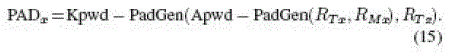
| In [10], the PadGen function is the key component in constructing the 16-b pads to cover code the two 16-b access
password halves (ApwdM and ApwdL). The pad-generation function retrieves the individual bits of the Apwd and Kpwd
from the memory locations by manipulating random numbers and concatenates these bits to form a 16-b pad. A brief
description of the PadGen function is provided in the following. Let us represent the 32-b Apwd and Kpwd in binary (base
2) as |
 |
 |
| The 16-b random numbers RTx and RMx generated by the tag and
manufacturer in hexadecimal (base 16) are |
 |
 |
| Each digit of RTx and RMx is used to ndicate a bit location in
Apwd, and these bits are concatenated to form a 16-b output
in hexadecimal (base 16) representations as |
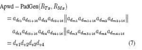
| Apwd − PadGen(RTx,RMx) |
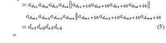 |
| where dv1dv2dv3dv4 is the decimal (base 10) notation.
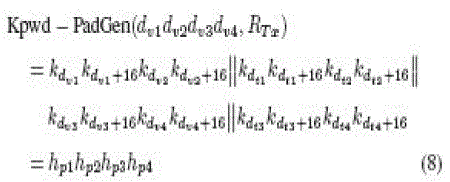
The PadGen is again performed over Kpwd using the previously generated v1dv2dv3dv4 to indicate a bit location in Kpwd,
and these bits are concatenated to form a 16-b PAD. The resulting PAD would then be expressed as |
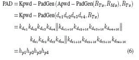 |
| where hp1hp2hp3hp4 is the hexadecimal (base 16) notation. |
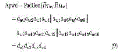
| C. Modified Scheme |
| As shown in the previous session, the first-round PadGen performs over the access password, as indicated in (5), while the
second-round PadGen performs over the kill password to generate the desired PAD, as indicated in (6). However, different
PADs can be generated by reconfiguring the concatenate operation. If we perform the following concatenate operation, the
first-round PadGen performs over the access password as |
 |
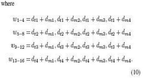
| where dv1dv2dv3dv4 is the decimal (base 10) notation. |
| Then, the second-round PadGen performs over the kill password. Instead of (6), the resulting PAD would then be expressed as |
 |
| where hp1hp2hp3hp4 is the hexadecimal (base 16) notation. A more complex anipulation on RTx and RMx to indicate a bit
location in Apwd and Kpwd can be formulated to increase the security level. For the present proposed methodology, the
first-round PadGen performs over the access password as |
 |
 |
| After the second-round PadGen performs over the kill password, the resulting PAD would then be expressed as |
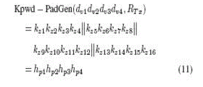 |
 |
| D. Security Considerations |
| The original scheme proposed by Konidala et al. utilizes the tag’s access and kill asswords and a PadGen chain of length
two for tag–reader mutual authentication [10]. However, practical attacks can effectively disclose the access and kill
passwords. In [11], the vulnerability analysis indicates that the original scheme contains a security weakness. If the
adversary sends the random number to the reader such that all the hexadecimal digitals in RTx have the same value (i.e.,
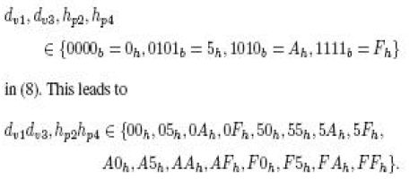
RTx = KKKKh), it can be deduced that all the bits in each of the hexadecimal digits dv1, dv2, hp3, hp4 ∈ {0000b = 0h,
1111b = Fh} in (6). This leads to dv1dv2, hp3hp4 ∈ {00h, 0Fh, F0h, FFh}. The adversary can then obtain the eight LSBs of
ApwdM and ApwdL by computing the following: |
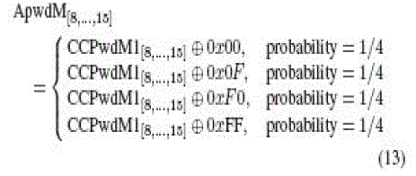 |
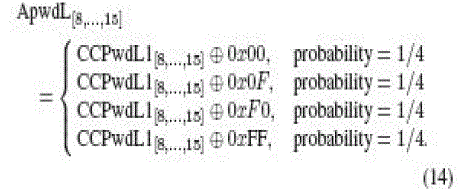 |
| The adversary can obtain the eight LSBs of ApwdM and ApwdL with a probability equal to 1/4 each. Results of further
analysis revealed that the 16 MSBs of the access password can be obtained with a probability greater than 1/32. In addition,
an attacker can recover the entire kill password with a probability equal to 1/4 [11].For a security comparison, we apply the
same attack scenario for our modified scheme (8). It can be deduced that all the bits in each of the hexadecimal digits |
 |
| Under this condition, an adversary will be able to extract the 16 b of the access password with a probability equal to 1/16,
which is more secure than the original scheme. For another modified scheme (11), the values of dv1, dv2, dv3, dv4, hp1,
hp2, hp3, and hp4 are calculated by adding two random numbers RTx and RMx. Using RTx = KKKKh, an adversary will not
be able to extract the 16 b of the access password without knowing RMx. |
DESIGN AND IMPLEMENTATION |
| A. Data Encoding Architecture |
| According to the EPC C1G2 protocol, a tag communicates with an interrogator using backscatter modulation, in which the
tag switches the reflection coefficient of its antenna between two states in accordance with the data being sent. Tags encode |
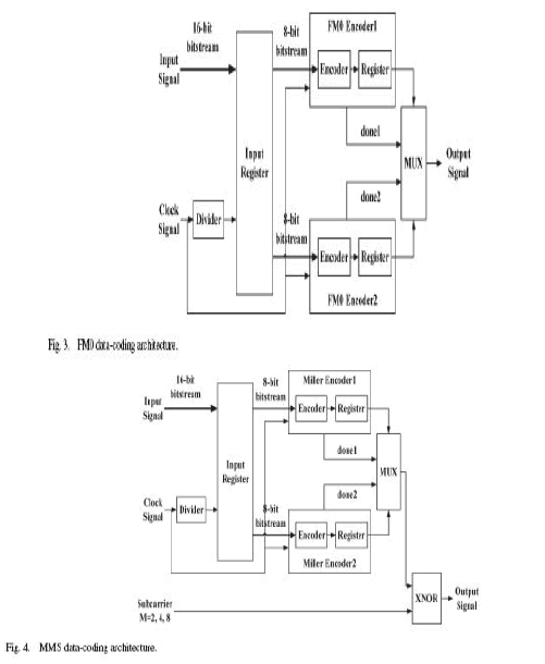 |
| the backscattered data as either FM0 baseband or the Miller modulation of a subcarrier at the data rate [25]. These two
kinds of encoding architectures, FM0 and Miller-modulated subcarrier (MMS), are proposed in this work. A detailed
definition of FM0 and MMS is described in [6]. The following is a brief definition of FM0 and MMS. A binary “1” is
constant during a symbol time, and a binary “0” has a state transition in the middle of a symbol, or the FM0 symbol can, in
turn, be XORed with square waves of up to eight times higher in frequency to form an MMS. In addition, baseband Miller
inverts the baseband value between adjacent binary values of zero. Finally, the resulting waveform is multiplied by a square wave ofM subcarrier cycles per bit, whereM is equal to two, four, or eight. The design of the FM0 encoding architecture is
shown in Fig. 3. The frequency divider divides the original clock signal frequency by two and is processed as a clock signal
to trigger the first register. The encoder is triggered by the original clock signal. The first input register is used to save the
input data for further encoding processes. The encoded information will be stored in the register and will output the final
results in sequence. The coding structure of MMS is similar to that of FM0. |
| Fig. 4 shows the MMS coding architecture. The frequency divider divides the original clock signal to trigger the first
register that stores the input data. The original clock is applied to the encoder as a trigger signal. The encoding result is
bitwised with a subcarrier through the XNOR gate. The Synopsys PrimePower platform is applied to simulate power
consumption with different input patterns on the FM0 and MMS coding architectures. In Fig. 5, there is a maximum power
consumption of FM0 when the input pattern is “01010101_01010101,” and the power is 3.367 × 10⁻⁵ W. The MMS
coding architecture |
 |
 |
| dissipates more power than that of FM0. The maximum power consumption for MMS encoding occurs when the input
pattern is “11111111_11111111.” The corresponding maximum power is 3.741 × 10⁻⁵, 3.993 × 10⁻⁵, and 4.493 × 10⁻⁵
W for M = 2, 4, and 8, respectively. |
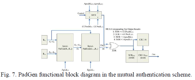
| B. PadGen Mutual Authentication Architecture |
| The PadGen function is the key function used to produce a cover-coding pad to mask the tag’s access password before
transmission. The implementation of the PadGen function also requires the random number generator to produce RTx and
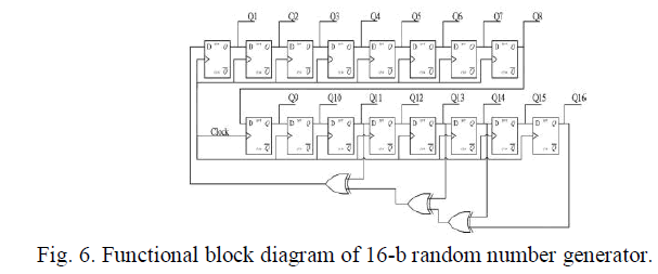
RMx. A typical 16-b linear feedback shift register (LFSR) is used to generate pseudorandom numbers. An LFSR with a
well-chosen feedback function can produce a sequence of bits that appears random and has a very long cycle. For an n-bit
LFSR, the LFSR can generate a (2n − 1)-b-long pseudorandom sequence before repeating. A maximum-length LFSR
produces an m-sequence (i.e., cycles through all possible 2n − 1 states within the shift register except the state where all
bits are zero). However, an LFSR with a maximal period must satisfy the following property: The polynomial formed from
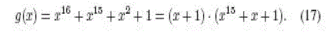
a tap sequence plus the constant 1 must be a primitive polynomial modulo 2 [26]. In this paper, the Fibonacci LFSR was
implemented because it is more suitable for hardware implementation than the Galios LFSR. The feedback polynomial is
x16 + x14 + x13 + x11 + 1. The architecture of the 16-b random number generator is shown in Fig. 6. is performed on the
tag’s 32-b access password Apwd = a0a1a2a3 . . . a31, which is broken up into two parts—the 16 MSBs of the access
password as ApwdM and the 16 LSBs denoted as ApwdL. The hexadecimal (base 16) notation of the 16-b random numbers RTx and RMx generated by the tag and manufacturer are expressed as RTx = dt1dt2dt3dt4 and RMx = dm1dm2dm3dm4,
respectively. Using each of the four hexadecimal digits in RTx (or RMx) to indicate a bit address within ApwdM or ApwdL,
PadGen then selects those bits from ApwdM and ApwdL to form the 16-b output pad, as shown in (5). The resulting output
dv1dv2dv3dv4 together with RTx will then perform PadGen over the 32-b kill password Kpwd (k0k1k2k3 . . . k31) to form
the 16-b output pad PADx. |
 |
| A multiplexer was utilized to allow for the selection of ApwdM, ApwdL, CCPwdL, or CCPwdM. The multiplexer then can
perform the XOR operation to obtain the following cover-coded passwords or the access password for mutual
authentication: |
 |
| The CRC function is implemented to protect and calibrate the commands/messages transmitted between tags and readers.
The generator polynomials used to implement the CRC is |
 |
| B. Implementation Results |
| The passwords were assumed to be Apwd = ABCDEF01 and Kpwd = 543210FE. The two random numbers RTx = 26D6
and RMx = 1FFF were generated by the random number generator. The calculated PAD1 was equal to B0D0. For ApwdM
= ABCD(hex), CCPwdM1 was calculated from ApwdM ⊕ PAD1 = 1B1D(hex), and the resulting CRC-16 code =
5A4E(hex). |
| The two random numbers RTx = 6B79 and RMx = 06C0 were generated by the random number generator. The calculated
PAD1 was equal to 88A8. For ApwdM = ABCD(hex), CCPwdM1 was calculated from APwdM ⊕ PAD1 = 2365(hex),
and the resulting CRC-16 code = 4B5D(hex). The simulation results of the final output are 23654B5D(hex), as shown in
Fig. 9. Table I lists the logic element gate counts and the power consumption summary of the design compiler report based
on TSMC 0.18-μm technology file. The experimental results of the original and modified schemes are also compared in
Table I. The modified scheme (8) occupies about the same area as the original scheme (6). In addition, the experimental
results show that the gate count and power consumption of the modified scheme in (11) are higher than that of the original
scheme (6). This is because the computation cost of PadGen in (11) is more than that of PadGen in (6) and (8). However,
the security level can be increased for PadGen in (11) by sacrificing the increase in the gate count and power consumption. |
CONCLUSION |
| In this paper, the functionality of the MMS and FM0 designs were verified using the micro controller based architecture.
Because the EPC Gen2 standard for Class 1 tags supports only a very basic security level, three different types of padgeneration
function were examined for tag–reader mutual authentication protocol in the ZIGBEE system environment. The
proposed scheme is feasible in improving the weakness of the EPC global C1G2 communication authentication scheme.
The hardware implementation of an ZIGBEE tag–reader mutual authentication scheme is also presented. This architecture
performs the PadGen function and tag’s access and kill passwords in achieving tag–reader mutual authentication. |
References |
- R. Want, âÃâ¬ÃÅEnabling ubiquitous sensing with RFID,âÃâ¬Ã Computer, vol. 37, no. 4, pp. 84âÃâ¬Ãâ86, Apr. 2004
- S. Garfinkel and B. Rosenberg, Eds., RFID : Applications, Security, and Privacy. Reading, MA: Addison-Wesley, Jul. 2005.
- S. Han, H. Lim, and J. Lee, âÃâ¬ÃÅAn efficient localization scheme for a differential-driving mobile robot based on RFID system,âÃâ¬Ã IEEE Trans. Ind. Electron., vol. 53, no. 5, pp. 3362âÃâ¬Ãâ3369, Dec. 2007.
- Class 1 Generation 2 UHF Air interface Protocol Standard. [Online]. Available: http://www.epcglobalinc.org/standards/
- Radio Frequency Identification for Item Management, 2nd ed., ISO/IEC 18000, Jul. 1, 2008.
- Ver. 1.0.9 EPCglobalRatifed Standard, EPC Radio-Frequency Identity Protocols Class-1 Generation-2 UHF RFID Protocol for Communications at 860 MHzâÃâ¬Ãâ960 MHz. [Online]. Available: http://www.epcglobalinc.org/standards
- S. L. Garfinkel, A. Juels, and R. Pappu, âÃâ¬ÃÅRFID privacy: An overview of problems and proposed solutions,âÃâ¬Ã IEEE Security Privacy, vol. 3, no. 3, pp. 34âÃâ¬Ãâ43, May/Jun. 2005.
- A. W. Stcphcn, E. S. Sanjay, L. R. Ronald, and W. E. Daniel, âÃâ¬ÃÅSecurity and privacy aspects of low-cost radio frequency identification systems,âÃâ¬Ã Security Pervasive Comput., vol. 2802, pp. 201âÃâ¬Ãâ212, 2004.
- J.-B. Eom, S.-B.Yim, and T.-J. Lee, âÃâ¬ÃÅAn efficient reader anticollision algorithm in dense RFID networks with mobile RFID read,âÃâ¬Ã IEEE Trans. Ind. Electron., vol. 56, no. 7, pp. 2326âÃâ¬Ãâ2336, Jul. 2009.
- D. M. Konidala, Z. Kim, and K. Kim, âÃâ¬ÃÅA simple and cost effective RFID tagâÃâ¬Ãâreader mutual authentication scheme,âÃâ¬Ã in Proc. Int. Conf. RFIDSec, Jul. 2007, pp. 141âÃâ¬Ãâ152.
- P. Peris-Lopez, T. Li, L. Lim, J. C. Hernandez-Castro, and J. M. Estevez- Tapiador, âÃâ¬ÃÅVulnerability analysis of a mutual authentication scheme under the EPC class-1 generation-2 standard,âÃâ¬Ã in Proc. RFIDSec, Jul. 2008,pp. 52âÃâ¬Ãâ63.
- P. Peris-Lopez, T.-L. Lim, and T. Li, âÃâ¬ÃÅProviding stronger authenticationat a low cost to RFID tags operating under the EPCglobalframework,âÃâ¬ÃÂinProc. IEEE/IFIP Int. Conf. EUC, Dec. 17âÃâ¬Ãâ20, 2008, vol. 2, pp. 159âÃâ¬Ãâ166.
- A. Juels, âÃâ¬ÃÅRFID security and privacy: A research survey,âÃâ¬Ã IEEE J. Sel. Areas Commun., vol. 24, no. 2, pp. 381âÃâ¬Ãâ394, Feb. 2006.
- S. Piramuthu, âÃâ¬ÃÅProtocols for RFID tag/reader authentication,âÃâ¬Ã Decis.upport Sys,., vol. 43, no. 3, pp. 897âÃâ¬Ãâ914, Apr. 2007.
- P. Peris-Lopez, J. C. Hernandez-Castro, J. M. Estevez-Tapiador, and A. Rib-agorda, âÃâ¬ÃÅRFID
|