ISSN ONLINE(2278-8875) PRINT (2320-3765)
ISSN ONLINE(2278-8875) PRINT (2320-3765)
Shivang Ghetia1, Nagendra Gajjar2 and Ruchi Gajjar3
|
| Related article at Pubmed, Scholar Google |
Visit for more related articles at International Journal of Advanced Research in Electrical, Electronics and Instrumentation Engineering
Discrete Cosine Transform (DCT) is a technique to get frequency separation. When DCT is applied on an image, it will give frequency segregation of an image since it is composed of DC value and range of low frequency values to high frequency values. DCT is very useful in image compression. When high frequency values are eliminated from image, it will give efficient compression at the cost of little degradation of image quality. But, the bottleneck is that when 2-Dimentional DCT is carried out on CPU, it takes much time since there is very high order of computation. To overcome this problem, Graphics Processing Unit (GPU) has opened the door for parallel processing. In this paper, we have implemented 2-D DCT with parallel approach on NVIDIA GPU using CUDA (Compute Unified Device Architecture). By applying here presented 2-D DCT algorithm for image processing has narrowed down the time requirement and has achieved speed up by factor 97x including data transfer timing from CPU to GPU and again back to CPU. So, parallel processing of 2-D DCT algorithm on GPU has fulfilled the purpose of fast and efficient processing of an image.
Keywords |
| DCT, GPU, compression, CUDA |
INTRODUCTION |
| The necessity for powerful computation is increasing rapidly. When it comes to advancement in the processing power of a computer, the first thing to be taken into account is the processorâÃâ¬ÃŸs operational frequency. But it cannot be expected to keep on increasing with time. The fact is that the clock frequency cannot be increased beyond some limit because of various factors such as overheating, etc, leaving the parallel computing as the only option for performance enhancement. Due to the hike in architectural and compiler complexity, multicore processors have always challenged engineers. But companies in the field of visual computing and graphic processing like NVIDIA, AMD has welcomed those challenges and opened new doors in the field of parallel and high performance computing [9]. |
| The CUDA, empowered by NVIDIA, integrated with high end C language which consists of additional functions, provides an interface between the developer and the device for the transferring of data and distribution of work between GPU and CPU [8]. It has the capability of identifying, programming, tracing a single core computation and performing multiple tasks in parallel as per the user requirement. |
| This flexible nature for parallel processing has attracted the researchers of image processing field. In image processing techniques, processing of images takes too much time which makes the system non real time. Researchers always try to narrow down this problem. GPU has launched new wings to solve this. Companies like NVIDIA have developed highly competent hardware and software to provide efficacious speed up for parallel processing. This invention has made revolution in field of parallel processing. Using its powerful techniques, optimized image processing algorithms can be implemented [10]. Along with image processing, image compression is also very crucial nowadays. Different compression algorithms are available which can be implemented on GPU for fast processing of compression. One of the most effective algorithms for image compression is Discrete Cosine Transform (DCT). When DCT is applied on an image, it will segregate its frequency components. As image is in 2-dimentional format, to get complete segregation of an image 2-D DCT must be applied. This paper shows the method for applying 2-D DCT on an image on a GPU. This will reduce the processing time and will give much accurate results. |
PARALLEL APPROACH TO IMAGE PROCESSING AND COMPRESSION |
| With the advancement of technology, world is now referring image processing as one of the most powerful field for automation and surveillance. Before using image processing, one must be sure that image should be processed within available time span. This only can make system near real time. Essentiality for expeditious processing of images is very pivotal in these days. Another bottleneck is, that in most the case, the size of an image is exorbitant and it has redundant data. So, it is essential that compression algorithm should be implied to zero down such redundant data but processing and implementing DCT compression algorithm on CPU takes too much time and makes the system non real time. In this scenario, GPU has provided solution for satisfying such fast computation. NVIDIA has developed CUDA to overcome the need for parallel processing [1]. |
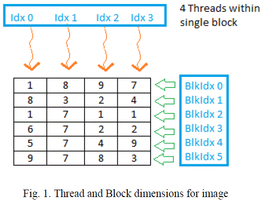
| Let an image of size m x n be processed and compressed according to 2-D DCT algorithm on GPU. Before implementing parallel processing approach, one must have knowledge of organizing block size and number of threads per blocks on the GPU. The presented algorithm for image compression takes number of rows (m) as number of block and number of columns (n) as the total number of thread within single block [3]. For example, consider image of size 4 x 6, as shown in figure 1. BlockIdx (block index) will vary from 0 to 5 and threadIdx (thread indexing) will vary from 0 to 3. |
 |
| Once the size of block is decided, raw image data needs to be converted into 1-D format for processing purpose. Raw data (image data) is converted into 1-D data using row major format. Once 1-D data is on hand, the proposed 2-D DCT algorithm can be applied. Different parts for implementation of 2-D DCT and compression algorithms are as below: |
| A. Convert N point data into 2N point data |
| As data is now available in 1-D format, it is required to convert that N point data into 2N point data, where N point data is data of each block. The N point data is converted into 2N point data by mirror reflection of N point data. This mirror imaged data of each block should be appended to corresponding block. This process is illustrated in the figure 2. In this figure, first part is the original data and later part is the mirror imaged data appended to its corresponding N point data. |
 |
| B. Apply 2N point CUFFT on 2N point data |
| Once 2N point data is on hand, Fast Fourier Transform (FFT) is applied. In CUDA, FFT is directly available. NVIDIA has developed „cufft.hâÃâ¬ÃŸ header file for optimized FFT on data. This CUFFT library is so rich that it provides an option for forward FFT and reverses FFT [12]. Data used here is in form of 1-D. So, for 1-D data, CUFFT library provides CUFFTPLAN1D. It also provides CUFFTPLAN2D and CUFFTPLAN3D for 2-D and 3-D data respectively [12]. Another feature of CUFFT library is that it provides different types of casting options like C2R (Complex data to Real data), R2C (Real data to Complex data) and C2C (Complex data to Complex data) [12]. For applying CUFFT (CUDA FFT), some parameters should be passed. These parameters are: |
| 1) Number of points in FFT, i.e. 2N |
| 2) Batch size, that will be same as number of columns of an image |
| 3) Type of FFT, that will be CUFFT_FORWARD as forward transformation is required [6]. |
| C. Converting 2N point data into N point data |
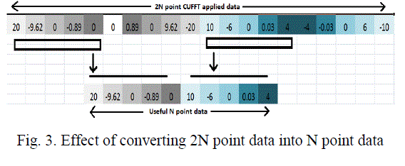
| After CUFFT data is available, 2N point data should be converted back into N point data. CUFFT applied data is of 2N point. In each 2N point data, first N point data is significant and the other N point data is a negative mirror image of the first N point data. So, from each 2N point data, the first N point data is conserved and remaining N point data is neglected. Raw data is now formed by collecting first N point of each 2N point data. This is shown in figure 3. |
 |
| D. Transform of N point data for converting row major format to column major format |
| Above mentioned N point data is now required to get transformed. Initially, data of an image is in 2-D form and this 2- D data is converted into 1-D using row major format. On this row major formatted data CUFFT and above mentioned steps are applied. Next step is to convert this processed 1-D N-point data into column major format for further processing. For converting this N point data into transposed N point data, kernel must be written with great calculation of launching threads and indexing these threads [11]. Here, thread indexing will vary from 0 to total number of rows. For each thread, there will be number of columns time iterations. For every iteration, thread index is offset added to multiplication of iteration index and number of rows. |
| E. Convert Transposed N point data into 2N point data and apply CUFFT |
| Transposed N point column major formatted data is now converted into 2N point data. Here, procedure of converting N point data into 2N point data is same as the previous one. But the only difference will be that now number of thread in each block is equal to number of rows and total number of batch is equal to number of columns. This interchange between block size and total number of blocks is due to column major format data. Once 2N point data is ready to use, this data is used for applying CUFFT [6]. Here also it is essential to be attentive for passing argument to CUFFTPLAN1D [12]. As data is now on column major format, batch size will be equal to pervious block size [6]. Number of point for applying FFT is also 2N point. Once CUFFT_FORWARD is applied on this 2N point column major formatted data, data is multiplied with twiddle factor. In twiddle factor multiplication, the total number of point will be 2N. For each 2N point data, first N point data is multiplied with its corresponding twiddle factor of 2N point. |
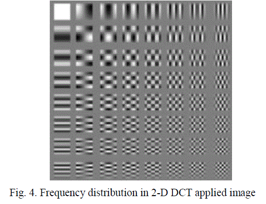
| Once each first N point data of each 2N point data is multiplied with twiddle factor, this 2N point data is required to convert back to N point with the purpose of making data quantized and compressed. To convert into N point data from each 2N point data, first N points are gathered and are put together. Now this gathered data is ready to get quantized and compressed. If we convert this N point 1-D data into 2-D data and again generate an image from it, it will result in frequency separation of the image, similar to DCT of an image. Up-Left corner contains the DC value of an image and as going from up to down or left to right, frequency get increased [13]. Sample image that shows the frequency separation is shown in figure 4. |
 |
| F. Quantization of N point data |
| N point data is required to get scanned in particular fashion. Zig-zag scanning is used to make data in such a form that will give gradual rise in frequency from left to right [15]. Pattern for zig-zag scanning (starting with 0 and ending with 63) is shown in figure 5. |
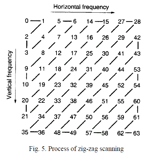 |
| For this purpose, kernel must be written prudently. The total number of thread that should be launched depends on two conditions. These conditions differ in terms of part for which loop indexing is less than width of an image and part for which loop indexing is greater than width of an image. Loop indexing will be the total number of diagonal scanning lines in zig-zag scanning. In figure 5, loop indexing will vary from 0 to 12 as there are 13 diagonal scanning lines. Flag has been used for getting the idea about current status of scanning line. For loop indexing less than width of an image, |
| flag= loop_index+1; |
| But for loop indexing greater then width of image thread indexing will be somewhat different. It will be as below: |
| flag=width – (loop_index+1)%(width); |
| Now it is required to check whether data is either on upper or in lower half triangle on an image. Once this is decided, it is also required to check whether the loop indexing is odd or even. So, there will be total four conditions to check, depending on upper part or lower part and even or odd indexing. |
| Let, width = width of an image |
| Hight = hight of an image |
| id= thread indexing |
| loop-indexing=i=width+hight-1 |
 |
| Once this scanning is over, we have frequency separated data in 1-D format. Now this data can be used for implementing quantization algorithm. For compression purpose, lower part of this scanned 1-D data is neglected and former data is quantized using standard quantization table. This will eliminate high frequency components and will zero down the redundancy. Run length coding can be used for compression of such redundant data [16]. Other compression techniques can also be applied. |
| G. Regeneration of Image |
| Compressed data is now required to generate original data back. For that, inverse quantization is applied [16]. Once inverse quantization is applied, all the previous kernels are implemented in reverse order. It will follow the following steps: |
| - Convert N point data into 2N point |
| - Apply 2N point CUFFT_INVERSE |
| - Apply Transpose after converting into N point data |
| -Apply 2N point conversion and again CUFFT_INVERSE |
| - Apply twiddle factor multiplication |
| Implementation of all above kernel will generate the original raw data of image but it is somewhat distorted due to quantization. But PSNR (Peak Signal to Noise Ratio) is still in acceptable range. PSNR is mostly defined via Mean Square Error (MSE) [17]. MSE can be calculated as, |
 |
OUTPUT RESULTS AND SPEED UP OF ALGORITHM |
| Algorithm for image compression can be implemented of NVIDIA GPU which is CUDA enabled. For processing of image, binary file of image is required. We have used Matlab to convert required image intro binary file. Once binary file is generated, this binary is imported in Visual Studio because Visual Studio can make use of CUDA Runtime Toolkit [9]. |
| This binary data is processed on GPU and after all computations, this data is written back into a binary file, and using this resulting binary file, final image can be generated [7]. Different sizes of images are tested and their resulting images are also presented here. While comparing this algorithm with another algorithm for processing, one should keep processing time and PSNR of resulting image on eyes. Quantization is also a functional part. Depending on compression requirements, different compression algorithms can be implementation after zig-zag scanning. Results depicted here are without any quantization so to get idea about how much exact image can be generated. Processing time is measured in milli-seconds (ms) here. |
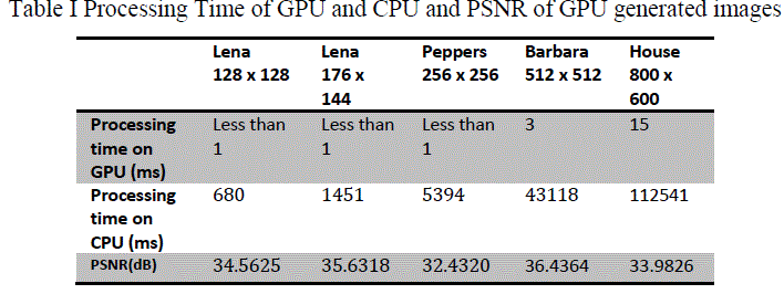 |
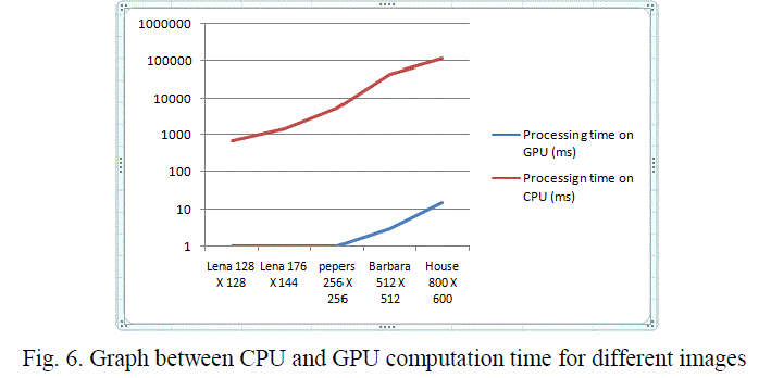
| When we plot these data on graph, figure 6, it will illustrate how efficient the use of GPU for high computation rather than CPU. Graph shows that as size of image goes on increasing, it takes much higher time on CPU but processing of same image on GPU will take few milli-seconds only. |
 |
CONCLUSION |
| After the successful implementation of image processing and compression DCT algorithm on GPU, processing of highly large images such as images from satellite can also be implemented. In this case, it is crucial that images taken by the satellite is processed there on the satellite and is transmitted on the Earth. To make processing of such massive image faster, GPU will help for parallel processing. Implementation of compression algorithm will help in reducing bandwidth requirement for transmission of processed data. Here results directly depict the faster processing compared to CPU, but the only threat is for transfer of data from CPU to GPU or vice-versa. Research is going on for direct feeding of data into GPU. |
| As FFT and transformation is used here for processing of an image, wavelet transform can also be implemented on GPU for processing and compression of image. Other aspects for processing images on GPU are the accuracy of processed data as it has Special Function Units. When data is to be handled with much accuracy and numbers after decimal point are also important, GPU will serve best purpose in that computation. As current technology uses image processing as one of its hand, processing and compression of such images can be deployed in GPU with alluring results. |
References |
|