International Journal of Advanced Research in Electrical, Electronics and Instrumentation Engineering
ISSN ONLINE(2278-8875) PRINT (2320-3765)
ISSN ONLINE(2278-8875) PRINT (2320-3765)
Jeena Joy1, Athira Poovathody2, Athul R S2, Athul Subran2 and Basil Paul2
|
| Related article at Pubmed, Scholar Google |
Visit for more related articles at International Journal of Advanced Research in Electrical, Electronics and Instrumentation Engineering
The purpose of this project is to create a micro-controller based digital dice game using an electronic digital dice with the help of seven segmented display. The game designed is a two player one in which each of the player gets his turn to play with the dice and the player who reaches the target score (here it is taken to be 25) fastest is declared to be the winner .Both the players have one push button each which when pressed freezes the count on the digital dice and highlights it on the display. Each player has to submit the score by pressing the “submit score” button. The score of both the players and the status of who leads till that turn is displayed on the LCD screen.
INTRODUCTION |
| A digital dice is an electronic dice in which we can generate any numbers from 0 to 9 using 7 segmented displays. The difference between normal dice and digital dice is that we can only get dice range from 1 to 6 in normal dice.Here we are presenting a circuit to design a digital dice game using an electronic digital dice with the help of a seven segment display controlled by an 8051 microcontroller. The game designed is a two player, one in which each of the player gets his turn to play with the dice and the player who reaches the target score (here it is taken to be 25) fastest is declared to be the winner. Both the players have one push button each which when pressed freezes the count on the digital dice and highlight it on the display. Each player has to submit the score by pressing the “submit score” button. The score of both the players and the status of who leads till that turn is displayed on the LCD screen. Initially a message “game start push button” appears on the LCD display. Player 1 begins the game by pressing his button. A score appears and it gets recorded and displayed on the LCD when he/she submits it. Then a message appears on the LCD which says “player 2 choice”. Player 2 repeats the same process as player. The status of who leads is displayed on the LCD after every player’s turn. Now when player1 gets his next turn his present score gets added to his previous score and total score is displayed on the LCD. This process continues till either of the players crosses the preset target score in the programming. Here we use C programming. |
SEVEN SEGMENTED DISPLAY |
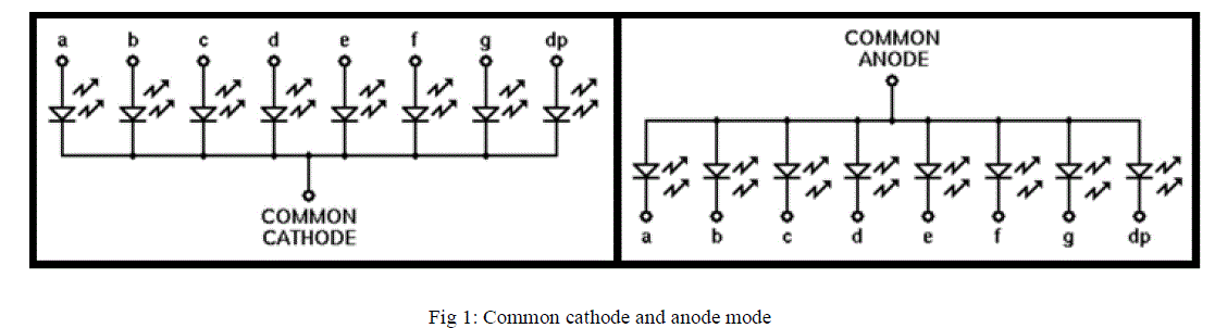
| A seven-segment display, or seven-segment indicator, is a form of electronic display device for displaying decimal numerals that is an alternative to the more complex dot-matrix displays. These are widely used in digital clocks, electronic meters, and other electronic devices for displaying numerical information. A seven segment display, as its name indicates, is composed of seven elements. Individually on or off, they can be combined to produce simplified representations of the Arabic numerals. Often the seven segments are arranged in an oblique (slanted) arrangement, which aids readability. In most applications, the seven segments are of nearly uniform shape and size (usually elongated hexagons, though trapezoids and rectangles can also be used), though in the case of adding machines, the vertical segments are longer and more oddly shaped at the ends in an effort to further enhance readability. |
| There are two types of seven segmented display common cathode and common anode. Here we uses common cathode mode. |
 |
LIQUID CRYSTAL DISPLAY(LCD) |
| A liquid crystal display (LCD) is a thin, flat panel used for electronically displaying information such as text, images, and moving pictures. Its uses include monitors for computers, televisions, instrument panels, and other devices ranging from aircraft cockpit displays, to every-day consumer devices such as video players, gaming devices, clocks, watches, calculators, and telephones. The most commonly used LCDs found in the market today are 1 Line, 2 Line or 4 Line LCDs which have only 1 controller and support at most of 80 characters. Among its major features are lightweight, portability and ability to be produced in much larger screen sizes than are practical for the construction of cathode ray tube (CRT) display technology. Its low electrical power consumption enables it to be used in battery-powered electronic equipment. It is an electronically-modulated optical device made up of any number of pixels filled with liquid crystals and arrayed in front of a light source (backlight) or reflector to produce images in color or monochrome. |
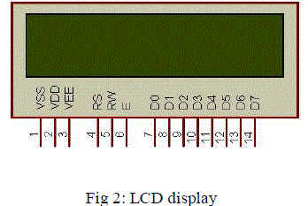 |
| Here LCD is used for showing whose turn is to play and the leading player in each round and point of each player. |
WORKING AND CIRCUIT DIAGRAM |
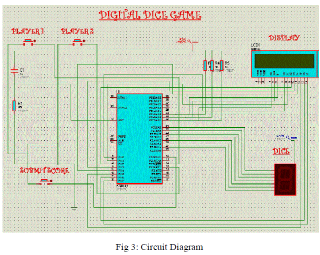 |
| The circuit diagram of the digital dice game is as shown. It consist of a 8051 micro controller, a seven segmented display, a LCD display, 3 press button etc. Out of 3 press button 2 press buttons are used by each player and one is used as submitting score button. 8051 is burned with C program. It is programmed in such a way that micro controller will generate a random number from 1 to 6 when player ones press button is pressed which is given as an interrupt to the micro controller. It is displayed on the seven segmented display. When the submitting score button is pressed micro controller add the points of player one/two and displayed on the LCD. After comparing each player’s points the person leading in the game is also displayed on the LCD screen. Initially a message is shown at the beginning of the game “game start push button”. When button is pressed player 1’s score is freezes and displayed on the seven segmented display. Now it asks to submit the score, after pressing submitting button the score of player one is displayed on LCD. A message showing that its player 2’s turn is displayed on the LCD. When player 2 presses the button his score gets freezes and displayed on the LCD. The status of which player leads is displayed on the LCD. This process continues till either of the player crosses the target score and that player is declared the winner and message is displayed on the LCD. Again a new game can be started afresh. |
CONCLUSION |
| The desired digital dice game has been designed and the complete system (including all the hardware components and software routines) is working as per the initial specifications and requirements of our project. Even certain aspects of the system can be modified as operational experience is gained with it. As the users play with the system, they develop various new ideas for the development and enhancement of the project. Number of players could be increased by making small changes in the programming and incorporating few additional hardware units. The score of the players can be viewed on the LCD. The status of the game and the information of which player’s turn is displayed on the LCD. The maximum score limit can easily be changed by making very slight modification in the programming. Number of players could be increased by making small changes in the programming and incorporating few additional hardware units like push buttons. Certain aspects of the system can be modified as operational experience is gained with it. As the users work with the system, they develop various new ideas for the development and enhancement of the project and many interesting games and applications can be developed |
ACKNOWLEDGEMENT |
| We hereby express our sincere gratitude to the Head of the Department of Electrical And Electronics Engineering, Prof. K. Radhakrishnan for providing us with the necessary arrangement for the completion of our project. We also thank our faculty advisor Prof. Elizabeth Sebastian for her valuable guidance. We express our sincere gratitude to our guide Ms. Siny Paul, Department of Electrical And Electronics Engineering, without whose valuable guidance and support the project would not have been a success. We thank her for the good will and encouragement extended to us. |
References |
|