Keywords
|
| Electric vehicle, BEMF, buck-boost converter, relay. |
INTRODUCTION
|
| Today, electric vehicles (EVs) have received much attention as an alternative to traditional vehicles powered by internal combustion engines with the advancement in battery technology and motor efficiency. The secondary batteries are the main energy sources of the EV. Thus, energy management is the most important key factor in EV or HEV design [1]-[2]. Moreover, the electric capacity of the battery will influence the endurance of electric vehicles. Generally, an energy management mechanism is very important for improving system efficiency and extending endurance. Therefore, well design charging strategies are key features in energy management of EV or HEV. |
| Electric vehicles are charged at charging stations by directly connecting to the AC mains which is the conventional method of charging. Nowadays EVs are charged through regenerative braking in which the vehicle’s momentum is captured and turned into electricity[3]. Recently various schemes are employed for converting the kinetic energy of the vehicle such as independent switching scheme, charging through ultra-capacitors, electronic throttle control system [ 4]-[5]. |
| Many advanced techniques, research results or control strategy related to the bi-directional converter are explored in succession. In reference [6], the power management and circuit topologies of single-phase and multi-phase bidirectional converters including non-isolated type and isolated type are all detailed. The non-isolated converters can be categorized into: buck, boost, and buck-boost types, which are low cost, compact size, without transformer, and easy to control due to having common ground. However, a transformer is still essential based on safety considerations, e.g. the voltage ratio between the primary side and secondary side is high enough or these two sides cannot be grounded together. Moreover, flyback type bi-directional converter is commonly used in many related applications [7]. The buck-boost type bidirectional converters not only possess step down and step up functions, but also can control the energy flow to achieve energy recovery, which is also suitable for many EV design [8]-[11]. |
| This paper presents a new charging method making use of the BEMF produced by the main motor of the vehicle. PIC is used as a control core. BEMF is sensed and the buck-boost converter is switched accordingly using a relay.Generally, an energy management mechanism is very important for improving system efficiency and extending endurance. Therefore, the new charging strategy is proposed which ensures charging of the EVs while it is running by making use of the BEMF produced by the motor |
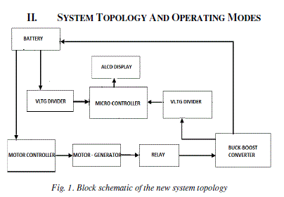
| Fig. 1 shows the system block diagram of the proposed charging feature. With this system, the battery can provide energy to motor through a motor driver. Variable speed is achieved by the motor controller circuitry. BEMF generated from motor is measured by the generator coupled with the motor and can be transferred to store in the battery. Besides, the bidirectional converter is switched into boost or buck mode depending on the charge of the battery. The battery voltage, back emf produced by the motor and boost voltage are displayed in the ALCD panel. A voltage divider is used to divide the voltage when fed to the microcontroller PIC16f877a. |
| Motor is driven by the battery array which is the source of power in any Electric Vehicle. Thus the battery charge must be retained as long as possible inorder to increase the legal limit of the vehicle. In the proposed system battery is charged by the BEMF produced by the motor of the vehicle during its run. |
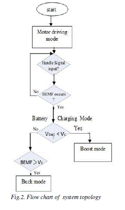
| When the back electromotive force (BEMF) generated by motor is higher than the battery voltage Vbat, then the buckboost converter is switched through a relay. Relay is turned on switching the bidirectional converter into the boost mode. Thus battery is charged in this mode which increases the legal limit of the vehicle. When the battery voltage is sufficient ie.between the required range to charge the battery then the relay is turned off. If the back emf is greater than that required to charge the battery then the buck-boost converter switched into buck mode inorder to limit the voltage. |
III. CONTROL ALGORITHM
|
| Control algorithm for entire system topology is as follows. |
| Step1:Ports are configured as input and output ports. |
| Step2: Initialize ALCD. |
| Step3:Initialize PWM by setting the CCPx pin of the microcontroller. |
| Step4: ADC is initialized. |
| Step6: Display the battery voltage . |
| Step7: Check if BEMF occurs or not |
| If BEMF occurs then goto step 8 else goto step7. |
| Step8: If the battery voltage Vbat is less than that required for charging then the relay is turned on. |
| Step8:Buck-boost converter is switched into boost mode providing sufficient voltage to charge the battery. |
| Step9:Else if the battery voltage is sufficient as per requirement then the relay is turned off. |
| Step10: Buck-boost converter is switched into the buck mode if the back emf is much greater than that required for charging. |
| Thus the back emf provides a battery backup and the battery charge is maintained which ensures increased legal limit for the vehicle sudden variation in the speed of vehicle is also avoided. |
| Mode 1: Motor driving mode: |
| In this mode, motor is driven by a battery array through a motor driver which inturn regulates the motor speed. The bidirectional converter will enter Mode I when the handle signal is detected, i.e., the battery offers energy for driving motor. Conversely, the system will detect whether BEMF occurs or not. If not, it represents system idle, and the program will return to initial state. On the other hand, the electric bike may be decelerated or in descent state as the BEMF occurs. And then, the system will automatically select Mode II to recycle energy to battery according to whether the BEMF higher than battery voltage or not. |
| Mode 2: Battery charging mode: |
| Initial battery voltage is displayed and if the battery voltage falls below a particular value that is the critical value required to drive the motor then the relay is turned on thereby switching the buck-boost converter into boost mode. The BEMF voltage is thus boosted and used for charging the battery. If the BEMF voltage is much greater than that required for charging the battery then the bidirectional converter is switched into buck mode maintaining the voltage within a range. |
IV. SOC ESTIMATION
|
| When the battery electrical parameters are obtained from the battery parameter estimation algorithm[12], in particular, the OCV, a voltage-based SOCV can be inferred. In the presence of battery hysteresis, the relationship between OCV and SOC is not a one-to-one mapping. Such a nonlinear relationship can be generalized as follows: |
 (1) (1) |
| As discussed in Section II, a switch type of hysteresis modelcan be used to model the battery hysteresis for iron phosphateLi-ion batteries. The model defines an additional hysteresis voltage ?h in OCV. By taking out the hysteresis voltage from OCV, the remaining voltage ?? can be monotonically mappedto SOC. The remaining ??, called the thermodynamic voltage,is defined as the difference between ??? and ?h : |
 . (2) . (2) |
| For the switch type of hysteresis model, ?h is governed by |
 (3) (3) |
| where?7 is a parameter to determine convergence rate, and ?hmax defines the boundaries of battery hysteresis. The values of ?7 and ?hmax can be obtained through experiments and vary with OCV (i.e. SOC). The hysteresis model in (3) describes a type of hysteresis with fast convergence to hysteresis boundaries from any point inside the boundary loop. With such a switch type of hysteresis model, the voltage -based SOCV is robust to the initial hysteresis voltage, that is, it is not necessary to require accurate knowledge of the initial hysteresis voltage because the hysteresis voltage governed by the model quickly converges to boundaries wherever it starts. The SOC estimation algorithm combines the voltage-based SOCV and a current-based SOCI through Coulomb counting. The final SOC estimate is a weighted combination of SOCV and SOCI as |
 (4) (4) |
| where 0<??<1 is the weighting factor. The combined SOC (k) will be used as a new starting point for the next update at the time instant ? +1. The benefit is to reduce the dependency on the initial SOC and increase algorithm robustness. |
| The weighting factor ?? is tuned based on the signal excitation level. For instance, the value of ?? decreases by 5%when the excitation level is lower than a threshold at the present time instant ?. On the other hand, the value of (1- ??) decreases by 5%, when the excitation level is higher than another threshold at the present time instant ?. The signal excitation level can be evaluated through monitoring the six elements in the diagonal matrix D or the determinant of D. It should be noted that real Li-ion batteries are not an ideal linear time invariant system. The model given by (4) is a simplified one for the estimation purpose, matching the Li-ion battery dynamics under a specific operation condition. Model uncertainties as well as the shifting of operation conditions, in combination with the use of the forgetting factor λ, will cause the increase of the values in one or several of the six elements in D, which should be decreasing in an ideal case of linear time invariant systems |
| Following the battery parameter estimation algorithm in |
| Section II, the SOC estimation algorithm is as follows: |
| Step 1: Starting with initialization, the algorithm sets the initial value of SOC(0) by reading the estimation result of previous operation from ROM. |
| Step 2: Obtain ??? from the battery parameter estimation algorithm and determine the validity of the estimated ???. If ??? is not valid, set the weighting factor ??=0 and go to Step 7. |
| Step 3: Update ?h using (2). |
| Step 4: Calculate ?? using (1). |
| Step 5: Infer SOCV(?) from ?? at the present time step. |
| Step 6: Tune the weighting factor ?? for SOCV and SOCI based on the signal excitation level. |
| Step 7: Read data (?) and calculate the SOCI(?) via |
| SOCI (?) = SOCI (? – 1) + (?)Δ? |
| where SOCI (? − 1) is from the previous time step, and ?(?)Δ? is the contribution from the Coulomb counting. |
| Step 8: Calculate the combined SOC(?) using (4) |
| Step 9: Determine whether it is the end of operation. If yes, save SOC(?) to NVM for next operation and end the algorithm. |
V. EXPERIMENTAL PROTOTYPE
|
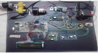
| PIC16f877a microcontroller is used as the control core. A 12V, 100 RPM NR-DC-ECO permanent magnet dc motor is used which is coupled to a generator to measure the BEMF of the motor. Speed of the motor can be varied by means of a motor driver. Motor driver used is L239D which is a dual driver and the rating is limited to 600mA. IL34063A is a bidirectional dc-dc converter used to operate in boost and buck mode according to the battery voltage and BEMF produced. |
VI. CONCLUSION
|
| The paper thus presents a new charging feature making use of the back emf produced by the motor which increases the legal limit of the vehicle and ensures its smooth run. Motor is driven by the battery array and simultaneously charged by the BEMF produced by the motor. Thus the disadvantages of conventional method of charging and charging during regenerative braking can be mitigated by employing the new charging feature. |
Figures at a glance
|
 |
 |
 |
| Figure 1 |
Figure 2 |
Figure 3 |
|
| |
References
|
- M. Verbrugge, D. Frisch, and B. Koch, “Adaptive energy management of electric and hybrid electric vehicles,” Journal of The ElectrochemicalSociety,vol. 152, no. 2, pp.A333-A342, 2005.
- N. Chaturvedi, R. Klein, J. Christensen, J. Ahmed, and A. Kojic, “Algorithms for advanced battery-management systems,” IEEE Control SystemsMagazine, vol. 30, no. 3, pp. 49-68, 2010.
- Jarrad.Cody,OzdeimerGol, ZorieNedu,AndrewNafaIshi,”Regenerative braking in electric vehicles”Honours Paper in Bachelor of Engineering degree,University of South Australia, School of Electrical and Information Engineering, pp.113-117, 2008.
- Binggang Cao ; Sch. of Mech. Eng., Xi''anJiaotong Univ. ; ZhifengBai ; Wei Zhang, “Research on control for regenerative braking of electric vehicle,”IEEE International conference on Vehicular Electronics and Safety, pp. 92-97,Oct 2005.
- Hao Zhang ; GuoqingXu ; Weimin Li ; Meilan Zhou, “Fuzzy logic control in regenerative braking system for electric vehicle,”IEEE journal ofInformation and Automation, International Conference 2012, pp.588-591, Jun 2012.
- J. S. Lai and D. J. Nelson, “Energy management power converters in hybrid electric and fuel cell vehicles,” Proceedings of the IEEE, vol.95, no. 4, pp.766-777, Apr. 2007.
- T. Bhattacharya, V. S. Giri, K. Mathew, and L. Umanand, “Multiphase bidirectional flyback converter topology for hybrid electric vehicles,” IEEETrans. Ind. Electron., vol. 56, no. 1, pp. 78-84, Jan. 2009.
- F. Caricchi, F. Crescimbini, F. Giulii-Capponi, and L. Solero, “Study of bi-directional buck-boost converter topologies for application in electricvehicle motor drives,” in Proc. IEEE APEC, pp. 287-293, Feb 1998.
- A. Boora, F. Zare, G. Ledwich, and A. Ghosh, “Bidirectional positive buck-boost converter,” in Proc. EPE-PEMC 2008, pp. 723-727,Sep.2008.
- X. Ren, X. Ruan, H. Qian, M. Li, and Q. Chen, “Dual-edge modulated four-switch buck-boost converter,” in. Proc .IEEE PESC, pp. 3635-3641,Jun. 2008.
|